EP0518751B1 - Vorrichtung und Verfahren zur Messung von Schüttgut, mit wenigstens einer Gewichtsmessung - Google Patents
Vorrichtung und Verfahren zur Messung von Schüttgut, mit wenigstens einer Gewichtsmessung Download PDFInfo
- Publication number
- EP0518751B1 EP0518751B1 EP92401589A EP92401589A EP0518751B1 EP 0518751 B1 EP0518751 B1 EP 0518751B1 EP 92401589 A EP92401589 A EP 92401589A EP 92401589 A EP92401589 A EP 92401589A EP 0518751 B1 EP0518751 B1 EP 0518751B1
- Authority
- EP
- European Patent Office
- Prior art keywords
- cell
- flap
- rig
- sensor
- weighing
- Prior art date
- Legal status (The legal status is an assumption and is not a legal conclusion. Google has not performed a legal analysis and makes no representation as to the accuracy of the status listed.)
- Expired - Lifetime
Links
Images


Classifications
-
- G—PHYSICS
- G01—MEASURING; TESTING
- G01G—WEIGHING
- G01G13/00—Weighing apparatus with automatic feed or discharge for weighing-out batches of material
- G01G13/02—Means for automatically loading weigh pans or other receptacles, e.g. disposable containers, under control of the weighing mechanism
- G01G13/022—Material feeding devices
- G01G13/024—Material feeding devices by gravity
Definitions
- the invention relates to a measuring device and method for bulk products, comprising at least one weight measurement, and more particularly, but not exclusively, for granular or powdery products, for example for cereals or the like.
- this type of measurement can also be part of a more complete set, as for example, for a measurement of the humidity level of said product.
- the device described in EP-A-46130 includes weighing means which may not be constantly used and more particularly, it is a measuring device for products, comprising at least one feed hopper. of the product, at least one cell intended to receive said product, a crew which is mounted movable back and forth vertically up and down with respect to a fixed frame, which crew comprises means for driving said cell in its movement, and a weighing sensor which is mounted on a part of the fixed frame and which is arranged to support the cell by ensuring its measurement, in a determined position thereof, the so-called weighing position, while detaching from said cell in at least one other position.
- the inventor proposes a particularly simple device and method which, among other things, protects the weighing sensor by not requesting it except when necessary (namely for initial measurements, during filling, and for final measurements ).
- the device according to the invention makes it possible to verify, as will be explained below, the calibration of the weighing sensor at each weighing cycle.
- the device according to the invention may also have only one motor, while many maneuvers are carried out by mechanical means combined with a single general movement.
- the device according to the invention comprises means of the aforementioned type in connection with EP-A-46130, but it is in particular remarkable in that the mobile assembly includes support means for the cell, which are arranged to in such a way that from said weighing position, a movement of the movable assembly in one direction dissociates it from the cell, the sensor dissociates from said cell in the other direction, while the cell is provided with 'A means of opening and closing for the evacuation at will of said product after treatment.
- the means for supporting the moving element and the sensor are arranged in such a way that the cell passes from the means for supporting the moving element to the sensor, during the movement of descent of the element and, on the contrary, from the sensor to the means for supporting the mobile assembly during its upward movement.
- the feed hopper comprises at least one discharge hatch which is provided with a shutter urged to close by a return means while an actuating means for its opening is provided to cooperate with a means combined with the mobile equipment.
- the means for actuating the shutter of the feed hopper has the form of a stop secured to said shutter while the combined means secured to the movable assembly is an arm intended to come to bear on said stop and causing the opening of said flap during the vertical movement of said moving assembly.
- the cell opening and closing means may include a flap which is arranged under said cell and which is requested to be closed by a return means while an actuating means is provided to cooperate with a combined conjugate means. fixed frame.
- the means for actuating the shutter of the cell has the form of a lever or stop secured to said shutter while the combined means secured to the chassis is an arm or finger intended to come press on said lever or stop and cause said flap to open during the vertical movement of said cell.
- An advantageous embodiment is remarkable in that it comprises at least two separate cells linked together by spacers.
- the sensor and the means of support for the moving part are arranged to cooperate with said spacers in order to ensure the support of the cells respectively in the weighing position by the sensor and in movement by the moving part.
- the device according to the invention can have various applications and when it is in particular intended to measure the moisture content of cereals, oilseeds or protein crops, by capacitive effect and that it comprises, as specified above, at least two cells, each cell can then advantageously form a measurement capacitor while the cells are electrically connected in parallel.
- a device according to the invention may advantageously have only one up-down engine for the mobile assembly.
- a preferred embodiment is remarkable in that the means for supporting the mobile assembly, the weighing sensor and the means for actuating the flap of the feed hopper and the flap for opening the cell, are arranged. in such a way that during a movement of descent of the moving part from an initial high position in which the cell is carried by said moving part, the flaps of the feed hopper and of the cell being closed and open respectively, we pass to a position where the cell rests on the weighing sensor, while during this descent the flap of the cell closes and a continuation of the descent leads to the opening of the hopper power supply, a rise in the moving assembly causing successively opposite situations.
- a completely advantageous method is remarkable in that operations a) and b) are carried out during a movement of descent of the mobile assembly and operations c) to e), during an ascent of said mobile equipment.
- the device according to the invention comprises a chassis 1 in particular formed here by a base 1a, a bracket 1b and a support 1c.
- a feed hopper 2 is fixed to the bracket 1b and a weighing sensor 3 is placed on the support 1c.
- the device also includes a movable assembly 4 which is arranged to be provided with a back and forth movement of vertical ascent-descent here by a worm 5 which is rotated at will in one direction or the other by a motor or servomechanism 6 (for example a bidirectional electric motor) mounted on the chassis, the movable element 4 being provided with conjugated threads of said screw, arranged in appropriate parts such as 4a and 4b of said movable element.
- a motor or servomechanism 6 for example a bidirectional electric motor
- the mobile assembly further comprises a support 4c intended to support a set of two cells 7a and 7b under which is disposed a recovery receptacle 8.
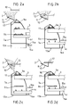
- the cells 7a and 7b are joined together by spacers shown diagrammatically in section through 9a, 9b in FIGS. 2a to 2e, the section plane of which is located precisely along a vertical plane passing between the said cells.
- the feed hopper 2 is provided with a hatch provided with a flap 10 biased in the closed position by a return means (not shown), which flap is equipped with a stop or cam 11 (FIG. 1 and FIGS. 2a to 2e).
- the stop 11, here in the form of a crank, is intended to cooperate with an arm 12 (FIGS. 1, and 2a to 2d), which is integral with the mobile assembly 4.
- the cells 7a and 7b each have a flap 13a, 13b at their lower part for discharging the product.
- the spacers 9a and 9b comprise means, in this case openings, intended to cooperate with corresponding elements, here projections, arranged on the sensor 3 and the support 4c so that the cells can be supported either by the support 4c, or by the sensor 3 depending on the position of the moving assembly relative to the fixed position of the sensor.
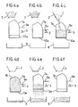
- the flaps 13a, 13b of the cells 7a, 7b are each biased in the closed position by a return means (not shown) and are provided with a lever 14a, 14b ( Figures 3a to 3d) intended to cooperate with a arm 15a, 15b secured to the chassis 1 and whose end only is shown diagrammatically in FIGS. 3a to 3d.
- the mobile assembly is in the high position, denoted I (FIGS. 2a, 3a, and 4a), position in which the cells are carried by the support 4c which cooperates with the spacer 9b.
- I FIGS. 2a, 3a, and 4a
- the hopper 2 is closed (urged to close by its return means), the arm 12 being considerably higher than the stop 11 while the flaps 13a, 13b of the cells 7a, 7b are in position open thanks to arms 15a and 15b fixed which rest on the levers 14a, 14b (see more particularly Figure 3a) against their return means.
- the cells 7a, 7b are open at rest, which is particularly advantageous (ventilation, complete emptying, air circulation allowing a rapid return to ambient temperature of a possible temperature sensor, ... ).
- the mobile assembly begins its descent by means of the motor 6 to reach a position II (FIGS. 2b, 3d and 4b), position in which the spacer 9a cooperates with the sensor 3, the latter thus supporting the cells 7a and 7b while simultaneously, the support 4c is released from the spacer 9b (see more particularly FIG. 2b).
- Position III corresponds to the filling of the cells.
- the mobile assembly ascends to a position denoted II ′ (FIGS. 2d, 3d, 4d) which corresponds to position II of FIGS. 2b, 3d, 4d, that is to say in which the hopper 2 has closed while the sensor 3 can measure the weight of the cells, but here with full cells.
- the device passes successively into the following positions: - initial position I Figures 2a, 3a, 4a - taring position II figures 2b, 3d, 4b - filling position III figures 2c, 3d, 4c - weighed position of full cells.
- II ' figures 2d, 3d, 4d - emptying and return position I ' Figures 2e, 3a, 4e, 4f.
- the shape of the cells is advantageous because it makes it possible to obtain self-leveling, that is to say the formation of a dome 16 (FIGS. 2d, 4d) of particularly reduced excess product. ensuring better reliability in repeating measurements at constant volume, but this feature is the subject of another patent. Between the cells, it is also possible to provide an inclined face 17 (FIGS. 1 and 2a to 2e) to ensure better flow of the excess product.
- the device according to the invention makes it possible to verify the sensor.
- the weighing sensor 3 is completely free, that is to say that the measurement value which it supplies corresponds to a "no-load” value or relative zero.
- any offset from this zero which can change over time (in particular depending on the temperature), can be known and it will be possible to take it into account in the result.
- the sensor 3 is for example of the gauge bridge type and at constant time.
- the side walls of the cells can constitute the armatures of the measurement capacitors.
- said cells can also be connected in parallel (the capacitors of the capacitors being added). The recording and processing of measurements is not dealt with more particularly here.
Landscapes
- Physics & Mathematics (AREA)
- General Physics & Mathematics (AREA)
- Weight Measurement For Supplying Or Discharging Of Specified Amounts Of Material (AREA)
Claims (14)
- Vorrichtung zur Messung von Erzeugnissen mit mindestens einem Einfülltrichter (2) für das Erzeugnis, mindestens einer zur Aufnahme des besagten Erzeugnisses bestimmten Zelle (7a, 7b), einem beweglichen Organ (4), das in vertikaler Richtung hin und her und in Bezug auf ein festes Grundgestell (1) aufwärts und abwärts bewegbar montiert ist, wobei das Organ (4) Mittel zum Mitnehmen der besagten Zelle (7a, 7b) bei seiner Bewegung aufweist, und mit einem Gewichtsmeßfühler (3), der an einem Teil (1c) des festen Grundgestells (1) montiert und derart angeordnet ist, daß er die Zelle zur Sicherstellung der Messung in einer vorgegebenen, Wägeposition genannten, Position von ihr trägt und sich von der besagten Zelle in mindestens einer anderen Position vollständig trennt, dadurch gekennzeichnet, daß das bewegliche Organ (4) Unterstützungsmittel (4c) für die Zelle (7a, 7b) aufweist, die derart angeordnet sind, daß ausgehend von der besagten Wägeposition eine Bewegung des beweglichen Organs (4) in einer Richtung dieses von der Zelle trennt und der Meßfühler sich von der besagten Zelle bei einer Bewegung in der anderen Richtung trennt, und die Zelle (7a, 7b) mit einem Mittel zum Öffnen und Schließen versehen ist zur wahlweisen Abführung des besagten Erzeugnisses nach der Bearbeitung.
- Vorrichtung zur Messung nach Anspruch 1, dadurch gekennzeichnet, daß die Unterstützungsmittel (4c) des beweglichen Organs (4) und der Meßfühler (3) derart angeordnet sind, daß die Zelle im Verlauf der Abwärtsbewegung des Organs von den Unterstützungsmitteln (4c) des beweglichen Organs (4) auf den Meßfühler (3) und im Gegensatz dazu im Verlauf seiner Aufwärtsbewegung vom Meßfühler (3) auf die Unterstützungsmittel (4c) des beweglichen Organs übergeht.
- Vorrichtung nach einem der Ansprüche 1 und 2, dadurch gekennzeichnet, daß der Einfülltrichter (2) mindestens eine Entleerungsöffnung aufweist, die mit einer Verschlußklappe (10) versehen ist, welche durch ein Rückstellmittel in Schließrichtung beansprucht ist, während ein Betätigungsmittel für ihre Öffnung vorgesehen ist, das mit einem fest mit dem beweglichen Organ verbundenen Mittel zusammenwirkt.
- Vorrichtung nach Anspruch 3, dadurch gekennzeichnet, daß das Betätigungsmittel für die Verschlußklappe (10) des Einfülltrichters die Form eines mit der besagten Verschlußklappe (10) fest verbundenen Anschlags (11) aufweist, während das fest mit dem beweglichen Organ (4) verbundene Mittel ein Arm (12) ist, der dazu bestimmt ist, sich an den besagten Anschlag anzulegen und im Verlauf der Vertikalbewegung des besagten beweglichen Organs die Öffnung der besagten Verschlußklappe herbeizuführen.
- Vorrichtung nach einem der Ansprüche 1 bis 4, dadurch gekennzeichnet, daß das Mittel zum Öffnen und Schließen der Zelle (7a, 7b) eine Verschlußklappe (13a, 13b) aufweist, die unter der besagten Zelle angeordnet ist und durch ein Rückstellmittel in Schließrichtung beansprucht ist, während ein Betätigungsmittel vorgesehen ist, das mit einem fest mit dem festen Grundgestell verbundenen Mittel zusammenwirkt.
- Vorrichtung nach Anspruch 5, dadurch gekennzeichnet, daß das Betätigungsmittel für die Verschlußklappe (13a, 13b) der Zelle (7a, 7b) die Form eines mit der besagten Verschlußklappe fest verbundenen Hebels oder Anschlags (14a, 14b) aufweist, während das fest mit dem Grundgestell verbundene Mittel ein Arm oder Finger (15a, 15b) ist, der dazu bestimmt ist, sich an den besagten Hebel oder Anschlag anzulegen und im Verlauf der Vertikalbewegung der besagten Zelle die Öffnung der besagten Verschlußklappe herbeizuführen.
- Vorrichtung nach einem der Ansprüche 1 bis 6, dadurch gekennzeichnet, daß sie mindestens zwei verschiedene Zellen (7a, 7b) aufweist, die über Stege (9a, 9b) miteinander verbunden sind.
- Vorrichtung nach Anspruch 7, dadurch gekennzeichnet, daß der Meßfühler (3) und die Unterstützungsmittel (4c) des beweglichen Organs so angeordnet sind, daß sie mit den besagten Stegen zusammenwirken, um jeweils die Unterstützung der Zellen (7a, 7b) in der Wägeposition durch den Meßfühler und bei der Bewegung durch das bewegliche Organ sicherzustellen.
- Vorrichtung nach einem der Ansprüche 7 und 8, insbesondere bestimmt zur Messung des Feuchtigkeitsgehalts von Getreide sowie öl- oder proteinhaltigen Früchten durch kapazitiven Effekt, dadurch gekennzeichnet, daß jede Zelle einen Meßkondensator bildet und die Zellen elektrisch einander parallelgeschaltet sind.
- Vorrichtung nach einem der Ansprüche 1 bis 9, dadurch gekennzeichnet, daß das bewegliche Organ (4) einen einzigen Motor oder Servomechanismus für die Aufwärts- Abwärtsbewegung aufweist.
- Vorrichtung nach der Gesamtheit der Ansprüche 2, 3 und 5, dadurch gekennzeichnet, daß die Unterstützungsmittel (4c) des beweglichen Organs (4), der Gewichtsmeßfühler (3) und die Betätigungsmittel (11, 12; 14a, 14b, 15a, 15b) für die Verschlußklappe (10) des Einfülltrichters (2) und für die Verschlußklappe (13a, 13b) der Öffnung der Zelle (7a, 7b) derart angeordnet sind, daß im Verlauf einer Abwärtsbewegung des beweglichen Organs (4), ausgehend von einer hohen Anfangsposition, in welcher die Zelle von dem besagten beweglichen Organ getragen ist und die Verschlußklappen (10; 13a, 13b) des Einfülltrichters (2) und der Zelle (7a, 7b) jeweils geschlossen und offen sind, in eine Position übergegangen wird, in der die Zelle auf dem Gewichtsmeßfühler (3) aufliegt, während im Verlauf dieser Abwärtsbewegung die Verschlußklappe (13a, 13b) der Zelle (7a, 7b) sich schließt und eine Fortsetzung der Abwärtsbewegung die Öffnung des Einfülltrichters (2) bewirkt und eine Aufwärtsbewegung des beweglichen Organs die umgekehrt aufeinanderfolgenden Vorgänge herbeiführt.
- Verfahren zur Messung mittels einer Vorrichtung nach einem der Ansprüche 1 bis 11, dadurch gekennzeichnet, daß es aus den folgenden Verfahrensschritten besteht:a) Austarieren der Meßzelle (7a, 7b) durch Wiegen im leeren Zustand, indem man die besagte Zelle auf dem Gewichtsmeßfühler aufliegen läßt;b) Füllen der Zelle (7a, 7b) mit dem zu analysierenden Erzeugnis, nachdem die Verschlußklappe (13a, 13b) der Zelle (7a, 7b) geschlossen worden ist, indem der Einfülltrichter geöffnet wird;c) Schließen des Einfülltrichters (2);d) Wiegen der so gefüllten Zelle (7a, 7b);e) Öffnen der Zelle (7a, 7b) zum Abführen des Erzeugnisses.
- Verfahren nach Anspruch 12, dadurch gekennzeichnet, daß während und/oder zwischen mindestens bestimmter der Verfahrensschritte a) bis e) andere Messungen als die Gewichtsbestimmung mittels entsprechender Sensoren vorgenommen werden.
- Verfahren nach einem der Ansprüche 12 und 13, dadurch gekennzeichnet, daß die Verfahrensschritte a) und b) im Verlauf einer Abwärtsbewegung des beweglichen Organs (4) und die Verfahrensschritte c) bis e) im Verlauf einer Wiederaufwärtsbewegung des besagten beweglichen Organs ausgeführt werden.
Applications Claiming Priority (2)
| Application Number | Priority Date | Filing Date | Title |
|---|---|---|---|
| FR9107216A FR2677760B1 (fr) | 1991-06-13 | 1991-06-13 | Dispositif et procede de mesure pour produits en vrac, comportant au moins une mesure de poids. |
| FR9107216 | 1991-06-13 |
Publications (2)
| Publication Number | Publication Date |
|---|---|
| EP0518751A1 EP0518751A1 (de) | 1992-12-16 |
| EP0518751B1 true EP0518751B1 (de) | 1995-12-13 |
Family
ID=9413791
Family Applications (1)
| Application Number | Title | Priority Date | Filing Date |
|---|---|---|---|
| EP92401589A Expired - Lifetime EP0518751B1 (de) | 1991-06-13 | 1992-06-09 | Vorrichtung und Verfahren zur Messung von Schüttgut, mit wenigstens einer Gewichtsmessung |
Country Status (4)
| Country | Link |
|---|---|
| US (1) | US5349876A (de) |
| EP (1) | EP0518751B1 (de) |
| DE (1) | DE69206688T2 (de) |
| FR (1) | FR2677760B1 (de) |
Families Citing this family (2)
| Publication number | Priority date | Publication date | Assignee | Title |
|---|---|---|---|---|
| JP3091988B2 (ja) * | 1993-01-04 | 2000-09-25 | 信越化学工業株式会社 | 樹脂粉末の可塑剤吸収量自動測定装置 |
| US7204164B2 (en) * | 2004-09-24 | 2007-04-17 | Kalidindi Sanyasi R | Apparatus for testing powder properties |
Family Cites Families (12)
| Publication number | Priority date | Publication date | Assignee | Title |
|---|---|---|---|---|
| US553606A (en) * | 1896-01-28 | Weighing flour-bin | ||
| US359525A (en) * | 1887-03-15 | Automatic grain-weighing machine | ||
| US1370226A (en) * | 1919-12-11 | 1921-03-01 | Leland S Rosener | Weighing and transferring apparatus |
| US2893602A (en) * | 1955-09-09 | 1959-07-07 | Barber Greene Co | Apparatus for measuring aggregate for mixture with asphalt |
| FR2098486A5 (de) * | 1970-03-24 | 1972-03-10 | Pouyaud Andre | |
| DE2060490A1 (de) * | 1970-12-09 | 1972-06-29 | Hesser Ag Maschf | Vorrichtung zum Abwaegen jeweils gleicher Mengen von stueckigen Guetern |
| US4168466A (en) * | 1977-10-21 | 1979-09-18 | Agridustrial Electronics, Inc. | Moisture tester |
| FR2488405A1 (fr) * | 1980-08-08 | 1982-02-12 | Magat Georges | Appareil permettant d'effectuer automatiquement le poids specifique de produits divers tels que produits alimentaires et notamment des cereales, et leur procede de pesage avec un tel appareil |
| EP0046130B1 (de) * | 1980-08-08 | 1985-11-21 | Georges Magat | Verfahren und Vorrichtung zum Ermitteln des Gewichtes per Hektoliter verschiedener Produkte, wie z.B. von Nahrungsmitteln, insbesondere von Getreide und körnigen Produkten |
| IE821584L (en) * | 1982-06-30 | 1983-12-30 | William Cashman | Metering device |
| EP0106613B1 (de) * | 1982-10-01 | 1989-12-06 | Kabushiki Kaisha Ishida Koki Seisakusho | Trichter für einen automatischen Wägeapparat |
| US4588091A (en) * | 1983-05-27 | 1986-05-13 | Intersystems, Inc. | Method and apparatus to determine quality of particulate material |
-
1991
- 1991-06-13 FR FR9107216A patent/FR2677760B1/fr not_active Expired - Fee Related
-
1992
- 1992-06-09 DE DE69206688T patent/DE69206688T2/de not_active Expired - Fee Related
- 1992-06-09 EP EP92401589A patent/EP0518751B1/de not_active Expired - Lifetime
- 1992-06-11 US US07/897,284 patent/US5349876A/en not_active Expired - Fee Related
Also Published As
| Publication number | Publication date |
|---|---|
| US5349876A (en) | 1994-09-27 |
| DE69206688D1 (de) | 1996-01-25 |
| EP0518751A1 (de) | 1992-12-16 |
| FR2677760A1 (fr) | 1992-12-18 |
| FR2677760B1 (fr) | 1993-10-15 |
| DE69206688T2 (de) | 1996-05-09 |
Similar Documents
| Publication | Publication Date | Title |
|---|---|---|
| FR2599142A1 (fr) | Systeme de dechargement et de pesee pour balance de combinaison | |
| FR2485733A1 (fr) | Dispositif automatique de fabrication d'echantillons destines a l'analyse | |
| EP0518751A1 (de) | Vorrichtung und Verfahren zur Messung von Schüttgut, mit wenigstens einer Gewichtsmessung | |
| FR2598223A1 (fr) | Systeme de pesee automatique | |
| JP2002526048A (ja) | 容器アンローディング装置 | |
| EP0161142B1 (de) | Vorrichtung zum Fördern von aufeinanderfolgenden geführten Artikeln zu einer Bearbeitungsstelle | |
| FR2598222A1 (fr) | Dispositif de mesure de densite apparente de produits delivres a une machine de pesee | |
| EP0469994A2 (de) | Schneckenanordnung zum Austrag des in einem Silo zurückgebliebenen Produktes | |
| EP0041901B1 (de) | Vorrichtung zum Greifen eines Containers oder dgl. mit Niveaudetektoren | |
| FR2537945A1 (fr) | Procede de regularisation du debit de sortie d'une ligne reliant des machines de production | |
| EP1353155A1 (de) | Verfahren und Vorrichtung zum fortlaufenden Wiegen von Gegenständen und eine entsprechende Einrichtung zum Kalibrieren von zweischaligen Seetieren | |
| FR2662420A1 (fr) | Machine a conditionner des sacs dans des installations remplisseuses-doseuses. | |
| EP0229787B1 (de) | Verfahren und automatische vorrichtung zur messung des gehalts an einem löslichen bestandteil in einem pulverartigen produkt | |
| FR2591334A1 (fr) | Balance de combinaison | |
| FR2792555A1 (fr) | Installation pour le tri d'objets, en particulier de coquillages, notamment d'huitres | |
| EP0360687A1 (de) | Automatisches System zum Füllen von Behältern mit länglichen Gegenständen wie grünen Bohnen | |
| FR2531785A1 (fr) | Scintillometre a liquide | |
| FR3046840B1 (fr) | Module de pesage d'un produit | |
| EP0007837B1 (de) | Vorrichtung zum Messen der Festigkeit von Zigaretten oder dgl. | |
| EP0046130B1 (de) | Verfahren und Vorrichtung zum Ermitteln des Gewichtes per Hektoliter verschiedener Produkte, wie z.B. von Nahrungsmitteln, insbesondere von Getreide und körnigen Produkten | |
| FR2643146A1 (fr) | Dispositif pour effectuer le dosage volumetrique de produits solides de formes et dimensions irregulieres et la distribution de ces produits | |
| BE401784A (de) | ||
| FR2535296A1 (fr) | Dispositif de prelevement pneumatique de matieres granuleuses ou pulverulentes | |
| EP0045227B1 (de) | Automatische Behälterfüllmaschine, insbesondere für Lebensmittel | |
| BE332551A (de) |
Legal Events
| Date | Code | Title | Description |
|---|---|---|---|
| PUAI | Public reference made under article 153(3) epc to a published international application that has entered the european phase |
Free format text: ORIGINAL CODE: 0009012 |
|
| AK | Designated contracting states |
Kind code of ref document: A1 Designated state(s): DE GB IT |
|
| 17P | Request for examination filed |
Effective date: 19930517 |
|
| 17Q | First examination report despatched |
Effective date: 19941117 |
|
| GRAA | (expected) grant |
Free format text: ORIGINAL CODE: 0009210 |
|
| ITF | It: translation for a ep patent filed | ||
| AK | Designated contracting states |
Kind code of ref document: B1 Designated state(s): DE GB IT |
|
| GBT | Gb: translation of ep patent filed (gb section 77(6)(a)/1977) |
Effective date: 19951213 |
|
| REF | Corresponds to: |
Ref document number: 69206688 Country of ref document: DE Date of ref document: 19960125 |
|
| PLBE | No opposition filed within time limit |
Free format text: ORIGINAL CODE: 0009261 |
|
| STAA | Information on the status of an ep patent application or granted ep patent |
Free format text: STATUS: NO OPPOSITION FILED WITHIN TIME LIMIT |
|
| 26N | No opposition filed | ||
| PGFP | Annual fee paid to national office [announced via postgrant information from national office to epo] |
Ref country code: GB Payment date: 19970602 Year of fee payment: 6 |
|
| PGFP | Annual fee paid to national office [announced via postgrant information from national office to epo] |
Ref country code: DE Payment date: 19970821 Year of fee payment: 6 |
|
| PG25 | Lapsed in a contracting state [announced via postgrant information from national office to epo] |
Ref country code: GB Free format text: LAPSE BECAUSE OF NON-PAYMENT OF DUE FEES Effective date: 19980609 |
|
| GBPC | Gb: european patent ceased through non-payment of renewal fee |
Effective date: 19980609 |
|
| PG25 | Lapsed in a contracting state [announced via postgrant information from national office to epo] |
Ref country code: DE Free format text: LAPSE BECAUSE OF NON-PAYMENT OF DUE FEES Effective date: 19990401 |
|
| PG25 | Lapsed in a contracting state [announced via postgrant information from national office to epo] |
Ref country code: IT Free format text: LAPSE BECAUSE OF NON-PAYMENT OF DUE FEES;WARNING: LAPSES OF ITALIAN PATENTS WITH EFFECTIVE DATE BEFORE 2007 MAY HAVE OCCURRED AT ANY TIME BEFORE 2007. THE CORRECT EFFECTIVE DATE MAY BE DIFFERENT FROM THE ONE RECORDED. Effective date: 20050609 |