EP0518586A1 - Rotary nozzle - Google Patents
Rotary nozzle Download PDFInfo
- Publication number
- EP0518586A1 EP0518586A1 EP92305220A EP92305220A EP0518586A1 EP 0518586 A1 EP0518586 A1 EP 0518586A1 EP 92305220 A EP92305220 A EP 92305220A EP 92305220 A EP92305220 A EP 92305220A EP 0518586 A1 EP0518586 A1 EP 0518586A1
- Authority
- EP
- European Patent Office
- Prior art keywords
- nozzle
- plate brick
- fixed plate
- slide plate
- molten steel
- Prior art date
- Legal status (The legal status is an assumption and is not a legal conclusion. Google has not performed a legal analysis and makes no representation as to the accuracy of the status listed.)
- Granted
Links
Images


Classifications
-
- B—PERFORMING OPERATIONS; TRANSPORTING
- B22—CASTING; POWDER METALLURGY
- B22D—CASTING OF METALS; CASTING OF OTHER SUBSTANCES BY THE SAME PROCESSES OR DEVICES
- B22D41/00—Casting melt-holding vessels, e.g. ladles, tundishes, cups or the like
- B22D41/14—Closures
- B22D41/22—Closures sliding-gate type, i.e. having a fixed plate and a movable plate in sliding contact with each other for selective registry of their openings
- B22D41/26—Closures sliding-gate type, i.e. having a fixed plate and a movable plate in sliding contact with each other for selective registry of their openings characterised by a rotatively movable plate
-
- B—PERFORMING OPERATIONS; TRANSPORTING
- B22—CASTING; POWDER METALLURGY
- B22D—CASTING OF METALS; CASTING OF OTHER SUBSTANCES BY THE SAME PROCESSES OR DEVICES
- B22D41/00—Casting melt-holding vessels, e.g. ladles, tundishes, cups or the like
- B22D41/14—Closures
- B22D41/22—Closures sliding-gate type, i.e. having a fixed plate and a movable plate in sliding contact with each other for selective registry of their openings
- B22D41/38—Means for operating the sliding gate
-
- B—PERFORMING OPERATIONS; TRANSPORTING
- B22—CASTING; POWDER METALLURGY
- B22D—CASTING OF METALS; CASTING OF OTHER SUBSTANCES BY THE SAME PROCESSES OR DEVICES
- B22D41/00—Casting melt-holding vessels, e.g. ladles, tundishes, cups or the like
- B22D41/14—Closures
- B22D41/22—Closures sliding-gate type, i.e. having a fixed plate and a movable plate in sliding contact with each other for selective registry of their openings
- B22D41/40—Means for pressing the plates together
Definitions
- the present invention relates to a rotary nozzle which is attached to the bottom shell of a molten steel vessel such as a ladle or tundish whereby a slide plate brick is rotated so as to adjust the degree of opening of nozzle bores depending on the relation between the slide plate brick and the fixed plate brick to control the rate of pouring of molten steel or the like.
- Rotary nozzles have been used widely with ladles for receiving the molten steel tapped from a converter to transport or pour the molten steel into molds, tundishes for receiving the molten steel from a ladle to pour the molten steel into molds and the like.
- the rotary nozzles of the hinged type in which a rotor including a slide plate brick is opened and closed by rotating it by a hinge have recently been used in great number due to its various advantages that the sliding surfaces can be exposed so as to confirm for example the damages to the plate surfaces of the fixed plate brick and the slide plate brick with the naked eye, that there is no need to prepare any stand-by set in case of the changing or the maintenance and repair of the bricks, that the operation is easy and so on.
- Such rotary nozzle of the hinged type is pivotably fitted to the base member attached directly or through a member to the bottom shell of a ladle, tundish or the like (hereinafter referred to as a molten steel vessel) and the reduction gear output from a driving source, e.g., a motor is transmitted through an intermediate gear to the gear of the rotor including the slide plate brick, mounted in a door, thus rotating the rotor and hence the slide plate brick and thereby adjusting the opening of the nozzle.
- a driving source e.g., a motor
- Fig. 6 is a sectional view of an example of the conventional rotary nozzle.
- numerical 51 designates the bottom shell of a molten steel vessel
- 52 a base member attached to the bottom shell 51 with bolts 53 and a fixed plate brick 54 is mounted in the base member 52.
- Numeral 56 designates a top nozzle projected through a bore formed through the bottom shell 51 of the molten steel vessel and the base member 52 and connected to a nozzle bore 55 of the fixed plate brick 54.
- Numeral 57 designates a fixed frame pivotably attached to the base member 52 with a hinge 58.
- Numeral 59 designates a rotor received in the fixed frame 57, arranged rotatably on a bearing guide 62 through a ball bearing 60, formed on the outer periphery thereof with a gear 61 meshed with a gear (not shown) connected to the driving source and receiving a slide plate brick 63 in the upper part thereof.
- Numeral 65 designates a collector nozzle connected to a nozzle bore 64 of the slide plate brick 63, and 66 a nozzle bore in the collector nozzle.
- Numeral 67 designates a plurality of spring seats which are provided within the fixed frame 57 to face the bearing guide 62 with a coiled spring 68 being mounted between each of the spring seats and the bearing guide 62.
- a door 70 is formed by the fixed frame 57, the rotor 59, etc.
- the door 70 is closed and fastened to the base member 52 so that the slide plate brick 63 is pressed against the fixed plate brick 54 by the coiled springs 68 and there is no danger of the leakage of the molten steel. It is to be noted that if necessary, the rotor 59 is rotated from the driving source and the degree of opening of the nozzle bores 55 and 64 is adjusted, thereby controlling the pouring rate of the molten steel. Also, in order to effect the maintenance and inspection of the change of the fixed plate brick 54 and the slide plate brick 63, the door 70 can be pivoted on the hinge 58 to open the door 70.
- the rotary nozzle of the above type has been widely put in practical use as a device for controlling the pouring rate of molten steel by virtue of the fact that it is small in size, light in weight end positive in operation.
- this type of rotary nozzle is disadvantageous in that while the center lines of the nozzle bores 55 and 64 of the fixed plate brick 54 and the slide plate brick 63 are in alignment as shown in Fig. 6 when these nozzle bores are fully open, where the slide plate brick 63 is rotated to reduce the degree of opening of the nozzle bores 55 and 64, there is caused a deviation between the center line of the nozzle bore 55 of the fixed plate brick 54 and the center line of the nozzle bores 64 and 66 of the slide plate brick 63 and the collector nozzle 65 as shown in Fig.
- the long nozzle 71 is fixed in place in a manner that its nozzle bore 72 is positioned in alignment with the nozzle bore 55 of the fixed plate brick 54 with the result that when the nozzle bores 55 and 64 are reduced in the degree of opening, there is the danger of the nozzle bore 66 of the collector nozzle 65 shifting from the nozzle bore 72 of the long nozzle 71 and thereby failing to pour the molten steel.
- the supporting member of the long nozzle 71 is provided with a joint to make a so-called oscillatory motion and this has not only the undesirable effect of making the construction extremely complicated and expensive but also the effect of making difficult the sealing between the molten steel vessel and the long nozzle 71 due to the movement of the long nozzle 71.
- the long nozzle 71 is inserted into a center runner such as a bottom pouring runner to pour the molten steel, there are many difficulties that the movement of the long nozzle 71 causes it to strike against the center runner and so on.
- the invention disclosed in Japanese Laid-Open Patent No.47-05905 is an example of the proposals heretofore made to overcome the foregoing problems of the conventional rotary nozzle.
- This invention is constructed so that the axis of rotation of an elongated frusto-conical slide member is arranged to make an acute angle (7 degrees according to an embodiment) with the central axis of a flow passage through the slide member and the outlet opening of the slide member flow passage is maintained at the same position in response to all the positions of the slide member, with the result that the outflowing molten material passes freely and vertically through the flow passage at the position of the slide member which completely opens the flow passage and the position of the nozzle bore in the lower part of the collector nozzle is not allowed to deviate at the throttled slide member positions.
- the invention disclosed in Japanese Laid-Open patent No. 2-263562 consists in a rotary nozzle which is intended to attain the same purpose as mentioned above and in which a discharge block contacting with an annular supporting casing has an outer peripheral surface whose contacting portion is formed into a spherical shape, thereby making uniform the pressure at the close contacting sliding surfaces of an upper block and the discharge block.
- a perforated plate is supported below a casing so that the static pressure of molten steel is directly applied to the perforated plate and an excessive interfacial pressure is produced at the contact surface between the peforated plate and the lower part of the casing, thereby giving rise to the danger of damaging the perforated plate.
- a slide plate brick and a colletor nozzle are combined as a unit to form a slide member or a discharge block thus making the manufacture difficult.
- the rotary nozzle is constructed so that the discharge block contacting with the annular supporting casing has an outer peripheral surface formed into a spherical shape to follow up an inclination error and therefore not only the construction is complicated and the working is difficult but also the follow-up fails to take place if the sliding of the spherical surface is not good thereby deteriorating the reliability.
- the slide member or the discharge block is pressed against the performed plate or the upper block by simply fastening the casing in place with bolts directly or through spring packs, the two are not uniform in contract pressure and the molten steel tends to leak; particularly, the two cannot be contacted closely if the precision of the inclined surface is not satisfactory.
- the former is so designed that the supporting ring supporting the slide member is provided with external teeth and the rack engaging with the external teeth is driven by the operating cylinder thereby rotating the slide member, the driving mechanism and hence the whole apparatus is extremely increased in size.
- the rotary nozzle of the latter invention has many disadvantages that the supporting ,987ng supporting the discharge block is provided with a worm gear so as to rotate it by a worm so that during the rotation of the worm gear the sliding surfaces of the discharge block and the upper block are separated thus giving rise to the danger of frequently causing troubles of molten steel leakage and so on and therefor its realization is difficult.
- the present invention has been made with a view to overcoming the foregoing deficiencies in the prior art, and it is the primary object of the present invention to provide a rotary nozzle which is simple in construction, is easy to manufacture its bricks, has no danger of molten steel leakage due to the uniform and close contact between its slide plate brick and fixed plate brick, and is capable of positively connecting its collector nozzle and long nozzle with each other.
- a rotary nozzle including a base member attached to the bottom shell of a molten steel vessel, driving means rotatably mounted on the base member, a fixed plate brick including a nozzle bore, having at least its sliding surface inclined wit an angle of ⁇ ° and attached to the base member, a slide plate brick including a nozzle bore, having at least its sliding surface formed into an inclined surface which matches with the sliding surface of the fixed plate brick and attached, along with a collector nozzle to supporting means, a frame arranged below the supporting means, pivotably attached like a door to the driving means and connected to the supporting means so as to permit a vertical displacement of the supporting means, and a plurality of spring means interposed between the frame and the supporting means.
- the angle of inclination ⁇ ° of the sliding surface of the fixed plate brick is selected between 5° and 15° relative to the horizontal surface or the lower end portion of the collector nozzle is formed into a spherical shape.
- the nozzle bores of the fixed plate brick and the side plate brick are fully open, the nozzle bores of the top nozzle, the fixed plate brick, the slide plate brick and the collector nozzle are aligned with one another so that the molten steel falls vertically and it is poured by way of the long nozzle.
- the rotation is transmitted to the slide plate brick and the collector nozzle through the supporting member so that the degree of opening between it and the nozzle bore of the fixed plate brick is adjusted and the rate of pouring is controlled.
- the perpendicular passing through the center of the nozzle bore of the fixed plate brick and the line passing through the centers of the nozzle bores of the slide plate brick and the collector nozzle cross each other at the lower end of the collector nozzle and thus the slide plate brick and the collector nozzle are always rotated about this point of intersection.
- the opening of the nozzle bore in the collector nozzle is always opened to the nozzle bore of the fixed long nozzle and therefore the molten steel can be positively poured into the nozzle bore of the long nozzle.
- the lower end portion of the collector nozzle into a spherical shape, it is possible to smoothly rotate the collector nozzle while maintaining the sealing quality at the joint.
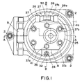
- Fig. 1 is a bottom view of an embodiment of the present invention.
- Fig. 2 is a sectional view taken along the line A-A of Fig. 1.
- Fig. 3 is a sectional view taken along the line B-B of Fig. 1.
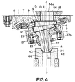
- Fig. 4 is a view useful for explaining the operation of the embodiment of the present invention.
- Fig. 5 is a schematic view showing the principle parts of another embodiment of the present invention.
- Fig. 6 is a sectional view showing a conventional rotary nozzle by way of example.
- Fig. 7 is a sectional view useful for explaining the operation of the rotary nozzle of Fig. 6.
- Fig. 1 is a bottom view of an embodiment of the present invention
- Figs. 2 and 3 are sectional views respectively taken along the lines A-A and B-B of Fig. 1.
- numeral 1 designates a base member attached with bolts 2 to a bottom shell 51 of a molten steel vessel directly or through other member and having its lower surface formed into an inclined surface 3 which is inclined with an angle of ⁇ ° with respect to the horizontal surface. In this embodiment, the angle ⁇ ° is selected 7.5°.
- Numeral 4 designates a through-hole in which is fitted a top nozzle 56 having a nozzle bore 56a, and 5 a recess formed below the hole 4 and having a bottom with a horizontal surface.
- Numeral 7 designates worm, gear rotatably arranged through a ball bearing 9 within an annular groove 6 formed on the outer periphery of the recess 5 of the base member 1, and 8 a worm which engages with the worm gear 7.
- Numeral 10 designates a fixed plate brick having an upper surface formed into a horizontal surface and a lower surface or a sliding surface formed into an inclined surface of the same angle ⁇ ° as the angle of inclination of the inclined surface 3 of the base member 1. With its upper surface on top, the fixed plate brick 10 is arranged within the recess 5 of the base member 1 and fastened to the base member 1 with bolts 12a through a fixing member 13a.
- Numeral 11 designated nozzle bore formed to perpendicularly cross the horizontal surface of the fixed plate brick 10 and communicated with the nozzle bore 56a of the top nozzle 56.
- Numeral 12 designates a supporting member composed of a body portion 13 inclined with an angle ⁇ ° relative to the horizontal surface and a leg portion 14 vertically dependent from the body portion 13.
- a recess 15 having a horizontal bottom is formed in the upper surface of the supporting member 12 and a bore 16 is formed through the leg portion 14 to be eccentric with the center of the recess 15.
- Numeral 18 designates a slide plate brick having the same external shape as the fixed plate brick 10 (however, the position of a nozzle bore 19 is different), arranged in the recess 15 of the supporting member 12 with the horizontal surface turned over and fixed in place with bolts 20 through a supporting member 21.
- Numeral 19 designates the nozzle bore formed to perpendicularly cross the horizontal surface of the slide plate brick 18.
- Numeral 22 designates a collector nozzle inserted and supported within the hole 16 of the supporting member 12, having its upper surface connected to the lower surface of the slide plate brick 18 and including a lower end portion formed into a spherical shape.
- Numeral 23 designates a nozzle bore formed through the collector nozzle 22 so as to perpendicularly cross the horizontal surface and to be eccentric with the central position.
- Numeral 25 designates a frame of a bottomed cylindrical shape which is arranged below the supporting member 12 so as to enclose it and formed in its bottom with a hole 25a into which is inserted the leg portion 14 of the supporting member 12.
- Arms 26 and 26a are arranged on one side of the longitudinal direction of the worm 8 of the frame 25 to project therefrom and are respectively connected by a pin 28 to support arms 27 and 27a which are dependent from the worm, gear 7, thereby forming a hinge 30.
- an arm 31 having a U-shaped engaging slot 32 and projecting therefrom, and fitted in the engaging slot 32 is a swing bolt 34 which is pivotably mounted on a support arm 33 depending from the worm gear 7 and fixed in place by a nut 35.
- Numerals 37 to 37c desingate spring means which are interposed between the frame 25 and the supporting member 12 and which are each composed of a guide shaft 38 having its lower end loose-fitted in a hole 36 formed in the bottom of the frame 25 and its upper end loose fittled in the hole formed in the supporting member 12 and a coiled spring 39 mounted on the guide shaft 38 through its spring seats.
- the spring means 37 to 37c are arranged at four locations in the illustrated embodiment, the spring means may be provided at three locations or five or more locations and also the coiled springs 39 may be replaced with crown springs.
- Numerals 41 and 41a respectively designate clamping bolts which are each slidably inserted into a hole 40 formed through the bottom of the frame 25 and threadedly fitted into a threaded hole 17 formed in the supporting member 12.
- These clamping bolts have the purpose of not only fastening together the supporting member 12 and the frame 25 as a unit but also adjusting the spring pressure of the spring means 37 to 37c, and the supporting member 12, which is adapted for rotation in cooperation with the frame 25, is permitted to independently displace vertically.
- Numeral 42 designates a long nozzle formed in the upper surface thereof with a recess 43 having a spherical shape corresponding to the shape of the lower end 24 of the collector nozzle 22 and provided w3ith a nozzle bore 44 of a greater diameter than the nozzle bore 23 of the collector nozzle 22 which in turn is rotatably connected to the long nozzle 42.
- the operation of the rotary nozzle according to the present invention will now be described.
- the nozzle bores 11 and 19 of the fixed plate brick 10 and the slide plate brick 18 are fully open, the nozzle bores 56a, 11, 19 and 23 of the top nozzle 56, the fixed plate brick 11, the slide plate brick 18 and the collector nozzle 22 are on the same vertical line and also the nozzle bore 44 of the long nozzle 42 is practically on the same vertical line as the nozzle bore 23 of the collector nozzle 22.
- the molten steel within the molten steel vessel is poured by falling substantially vertically through the nozzle bores of the respective nozzles from the nozzle bore 56a of the top nozzle 56.
- the frame 25 is pivoted on the hinge 30 thus closing the rotary unit. Then, the swing bolt 34 is engaged with the engaging slot 32 and the nut 35 is tightened. Thereafter, the clamping bolts 40 and 41 are loosened so as to apply an interfacial pressure to the sliding surfaces of the fixed plate brick 10 and te slide plate brick 18. At this time, the supporting member 12 and the slide plate brick 18 are uniformly urged upward by the spring means 37 to 37c provided at the plurality of locations and therefore the slide plate brick 18 can be pressed closely against the sliding surface of the fixed plate brick 10 with a uniform pressure.
- Fig. 5 is a schematic diagram showing the principal parts of another embodiment of the present invention. While, the embodiment of Figs. 1 to 3 shows the case in which the sliding surfaces of the fixed plate brick 10 and the slide plate brick 18 are inclined and the other surfaces are in the form of horizontal surfaces, as shown in Fig. 5, the sliding surfaces of the fixed plate brick 10 and the slide plate plate brick 18 may be inclined an the other surfaces may also be inclined in parallel to the sliding surfaces. In this case, however, it is necessary that the lower surface of the top nozzle 56 and the upper surface of the collector nozzle 22 are inclined in correspondence to these inclined surfaces.
- the lower surface of the base member 1 and the upper surface of the supporting member 12 are inclined in correspondence to the angle of inclination of the sliding surfaces of the fixed plate brick 10 and the slide plate brick 18, the lower surface of the base member 1 and the upper surface of the supporting member 12 may be formed to be horizontal.
- the worm gear 7 and the worm 8 are used to rotate the frame 25 and hence the slide plate brick 18, any other driving means such as a helical gear and a spur gear may be used.
- the lower end of the collector nozzle 22 is formed into a spherical shape so as to simplify its connection with the long nozzle 42 and rotate it smoothly, the lower end of the collector nozzle 22 may be formed into a flat shape in cases where it is not connected with the long nozzle 42. It is to be noted that while, in the above-described embodiments, the inclination angle ⁇ ° for the sliding surfaces of the fixed plate brick 10 and the slide plate brick 18 is set to 7.5° with respect to the horizontal surface, the results of experiments have confirmed that the proper range for the angle ⁇ is between 5°, and 15°.
- the rotary nozzle according to the present invention has the following effects.
Abstract
Description
- The present invention relates to a rotary nozzle which is attached to the bottom shell of a molten steel vessel such as a ladle or tundish whereby a slide plate brick is rotated so as to adjust the degree of opening of nozzle bores depending on the relation between the slide plate brick and the fixed plate brick to control the rate of pouring of molten steel or the like.
- Rotary nozzles have been used widely with ladles for receiving the molten steel tapped from a converter to transport or pour the molten steel into molds, tundishes for receiving the molten steel from a ladle to pour the molten steel into molds and the like. In particular, the rotary nozzles of the hinged type in which a rotor including a slide plate brick is opened and closed by rotating it by a hinge have recently been used in great number due to its various advantages that the sliding surfaces can be exposed so as to confirm for example the damages to the plate surfaces of the fixed plate brick and the slide plate brick with the naked eye, that there is no need to prepare any stand-by set in case of the changing or the maintenance and repair of the bricks, that the operation is easy and so on.
- Such rotary nozzle of the hinged type is pivotably fitted to the base member attached directly or through a member to the bottom shell of a ladle, tundish or the like (hereinafter referred to as a molten steel vessel) and the reduction gear output from a driving source, e.g., a motor is transmitted through an intermediate gear to the gear of the rotor including the slide plate brick, mounted in a door, thus rotating the rotor and hence the slide plate brick and thereby adjusting the opening of the nozzle.
- Fig. 6 is a sectional view of an example of the conventional rotary nozzle. In the Figure, numerical 51 designates the bottom shell of a molten steel vessel, and 52 a base member attached to the
bottom shell 51 withbolts 53 and afixed plate brick 54 is mounted in thebase member 52. Numeral 56 designates a top nozzle projected through a bore formed through thebottom shell 51 of the molten steel vessel and thebase member 52 and connected to anozzle bore 55 of thefixed plate brick 54. Numeral 57 designates a fixed frame pivotably attached to thebase member 52 with ahinge 58. Numeral 59 designates a rotor received in thefixed frame 57, arranged rotatably on abearing guide 62 through a ball bearing 60, formed on the outer periphery thereof with agear 61 meshed with a gear (not shown) connected to the driving source and receiving aslide plate brick 63 in the upper part thereof. Numeral 65 designates a collector nozzle connected to a nozzle bore 64 of theslide plate brick 63, and 66 a nozzle bore in the collector nozzle. Numeral 67 designates a plurality of spring seats which are provided within thefixed frame 57 to face thebearing guide 62 with a coiledspring 68 being mounted between each of the spring seats and thebearing guide 62. Thus, adoor 70 is formed by thefixed frame 57, therotor 59, etc. - With the rotary nozzle constructed as described above, during the pouring of molten steel the
door 70 is closed and fastened to thebase member 52 so that theslide plate brick 63 is pressed against thefixed plate brick 54 by thecoiled springs 68 and there is no danger of the leakage of the molten steel. It is to be noted that if necessary, therotor 59 is rotated from the driving source and the degree of opening of thenozzle bores fixed plate brick 54 and theslide plate brick 63, thedoor 70 can be pivoted on thehinge 58 to open thedoor 70. - The rotary nozzle of the above type has been widely put in practical use as a device for controlling the pouring rate of molten steel by virtue of the fact that it is small in size, light in weight end positive in operation. However, this type of rotary nozzle is disadvantageous in that while the center lines of the nozzle bores 55 and 64 of the
fixed plate brick 54 and theslide plate brick 63 are in alignment as shown in Fig. 6 when these nozzle bores are fully open, where theslide plate brick 63 is rotated to reduce the degree of opening of thenozzle bores fixed plate brick 54 and the center line of the nozzle bores 64 and 66 of theslide plate brick 63 and thecollector nozzle 65 as shown in Fig. 7 with the result that the molten steel emerging from the nozzle bore 55 of thefixed plate brick 54 changes its direction to fall towards the inner wall of the nozzle bore 66 of thecollector nozzle 65 and thereby to damage the inner wall of the nozzle bore 66 of thecollector nozzle 65 and also the solidified steel is accummulated on the inner wall thereby extremely reducing the life of theexpensive collector nozzle 65. - Further, with the latest rotary nozzles of the type used for the continuous casting of steel, while it is essential to provide a
long nozzle 71 below thecollector nozzle 65 as shown in Fig. 7, thelong nozzle 71 is fixed in place in a manner that itsnozzle bore 72 is positioned in alignment with the nozzle bore 55 of thefixed plate brick 54 with the result that when the nozzle bores 55 and 64 are reduced in the degree of opening, there is the danger of the nozzle bore 66 of thecollector nozzle 65 shifting from the nozzle bore 72 of thelong nozzle 71 and thereby failing to pour the molten steel. As a result, the supporting member of thelong nozzle 71 is provided with a joint to make a so-called oscillatory motion and this has not only the undesirable effect of making the construction extremely complicated and expensive but also the effect of making difficult the sealing between the molten steel vessel and thelong nozzle 71 due to the movement of thelong nozzle 71. In addition, where thelong nozzle 71 is inserted into a center runner such as a bottom pouring runner to pour the molten steel, there are many difficulties that the movement of thelong nozzle 71 causes it to strike against the center runner and so on. - The invention disclosed in Japanese Laid-Open Patent No.47-05905 is an example of the proposals heretofore made to overcome the foregoing problems of the conventional rotary nozzle. This invention is constructed so that the axis of rotation of an elongated frusto-conical slide member is arranged to make an acute angle (7 degrees according to an embodiment) with the central axis of a flow passage through the slide member and the outlet opening of the slide member flow passage is maintained at the same position in response to all the positions of the slide member, with the result that the outflowing molten material passes freely and vertically through the flow passage at the position of the slide member which completely opens the flow passage and the position of the nozzle bore in the lower part of the collector nozzle is not allowed to deviate at the throttled slide member positions.
- Also, the invention disclosed in Japanese Laid-Open patent No. 2-263562 consists in a rotary nozzle which is intended to attain the same purpose as mentioned above and in which a discharge block contacting with an annular supporting casing has an outer peripheral surface whose contacting portion is formed into a spherical shape, thereby making uniform the pressure at the close contacting sliding surfaces of an upper block and the discharge block.
- In accordance with the invention disclosed in Japanese Laid-Open Patent No. 47-5905, a perforated plate is supported below a casing so that the static pressure of molten steel is directly applied to the perforated plate and an excessive interfacial pressure is produced at the contact surface between the peforated plate and the lower part of the casing, thereby giving rise to the danger of damaging the perforated plate.
- Further, in accordance with Japanese Laid-Open Patent No. 47-5905 and Japanese Laid-Open Patent No. 2-263562, respectively, a slide plate brick and a colletor nozzle are combined as a unit to form a slide member or a discharge block thus making the manufacture difficult. Particularly, in the case of the latter invention, the rotary nozzle is constructed so that the discharge block contacting with the annular supporting casing has an outer peripheral surface formed into a spherical shape to follow up an inclination error and therefore not only the construction is complicated and the working is difficult but also the follow-up fails to take place if the sliding of the spherical surface is not good thereby deteriorating the reliability. Also, since the slide member or the discharge block is pressed against the performed plate or the upper block by simply fastening the casing in place with bolts directly or through spring packs, the two are not uniform in contract pressure and the molten steel tends to leak; particularly, the two cannot be contacted closely if the precision of the inclined surface is not satisfactory.
- Further, since the lower end portion of the slide member or the discharge block is in the form of an inclined surface, the connection with the fixedly arranged long nozzle is extremely troublesome.
- Still further, the former is so designed that the supporting ring supporting the slide member is provided with external teeth and the rack engaging with the external teeth is driven by the operating cylinder thereby rotating the slide member, the driving mechanism and hence the whole apparatus is extremely increased in size. On the other hand, the rotary nozzle of the latter invention has many disadvantages that the supporting ,987ng supporting the discharge block is provided with a worm gear so as to rotate it by a worm so that during the rotation of the worm gear the sliding surfaces of the discharge block and the upper block are separated thus giving rise to the danger of frequently causing troubles of molten steel leakage and so on and therefor its realization is difficult.
- The present invention has been made with a view to overcoming the foregoing deficiencies in the prior art, and it is the primary object of the present invention to provide a rotary nozzle which is simple in construction, is easy to manufacture its bricks, has no danger of molten steel leakage due to the uniform and close contact between its slide plate brick and fixed plate brick, and is capable of positively connecting its collector nozzle and long nozzle with each other.
- To accomplish the above object, in accordance with the present invention there is thus provided a rotary nozzle including a base member attached to the bottom shell of a molten steel vessel, driving means rotatably mounted on the base member, a fixed plate brick including a nozzle bore, having at least its sliding surface inclined wit an angle of ϑ° and attached to the base member, a slide plate brick including a nozzle bore, having at least its sliding surface formed into an inclined surface which matches with the sliding surface of the fixed plate brick and attached, along with a collector nozzle to supporting means, a frame arranged below the supporting means, pivotably attached like a door to the driving means and connected to the supporting means so as to permit a vertical displacement of the supporting means, and a plurality of spring means interposed between the frame and the supporting means.
- Then, in rotary nozzle, the angle of inclination ϑ° of the sliding surface of the fixed plate brick is selected between 5° and 15° relative to the horizontal surface or the lower end portion of the collector nozzle is formed into a spherical shape.
- When the nozzle bores of the fixed plate brick and the side plate brick are fully open, the nozzle bores of the top nozzle, the fixed plate brick, the slide plate brick and the collector nozzle are aligned with one another so that the molten steel falls vertically and it is poured by way of the long nozzle.
- When the frame is rotated by the driving means, the rotation is transmitted to the slide plate brick and the collector nozzle through the supporting member so that the degree of opening between it and the nozzle bore of the fixed plate brick is adjusted and the rate of pouring is controlled. At this time, the perpendicular passing through the center of the nozzle bore of the fixed plate brick and the line passing through the centers of the nozzle bores of the slide plate brick and the collector nozzle cross each other at the lower end of the collector nozzle and thus the slide plate brick and the collector nozzle are always rotated about this point of intersection.
- As a result, the opening of the nozzle bore in the collector nozzle is always opened to the nozzle bore of the fixed long nozzle and therefore the molten steel can be positively poured into the nozzle bore of the long nozzle. In this case, by forming the lower end portion of the collector nozzle into a spherical shape, it is possible to smoothly rotate the collector nozzle while maintaining the sealing quality at the joint.
- The above and the projects, features and advantages of the present invention will become readily apparent from the following detailed description of its embodiments taken in conjunction with the accompanying drawings.
- Fig. 1 is a bottom view of an embodiment of the present invention.
- Fig. 2 is a sectional view taken along the line A-A of Fig. 1.
- Fig. 3 is a sectional view taken along the line B-B of Fig. 1.
- Fig. 4 is a view useful for explaining the operation of the embodiment of the present invention.
- Fig. 5 is a schematic view showing the principle parts of another embodiment of the present invention.
- Fig. 6 is a sectional view showing a conventional rotary nozzle by way of example.
- Fig. 7 is a sectional view useful for explaining the operation of the rotary nozzle of Fig. 6.
- Fig. 1 is a bottom view of an embodiment of the present invention, and Figs. 2 and 3 are sectional views respectively taken along the lines A-A and B-B of Fig. 1. In the Figure,
numeral 1 designates a base member attached withbolts 2 to abottom shell 51 of a molten steel vessel directly or through other member and having its lower surface formed into aninclined surface 3 which is inclined with an angle of ϑ° with respect to the horizontal surface. In this embodiment, the angle ϑ° is selected 7.5°. Numeral 4 designates a through-hole in which is fitted atop nozzle 56 having a nozzle bore 56a, and 5 a recess formed below thehole 4 and having a bottom with a horizontal surface. Numeral 7 designates worm, gear rotatably arranged through a ball bearing 9 within anannular groove 6 formed on the outer periphery of therecess 5 of thebase member 1, and 8 a worm which engages with theworm gear 7. - Numeral 10 designates a fixed plate brick having an upper surface formed into a horizontal surface and a lower surface or a sliding surface formed into an inclined surface of the same angle ϑ° as the angle of inclination of the
inclined surface 3 of thebase member 1. With its upper surface on top, thefixed plate brick 10 is arranged within therecess 5 of thebase member 1 and fastened to thebase member 1 with bolts 12a through afixing member 13a. Numeral 11 designated nozzle bore formed to perpendicularly cross the horizontal surface of thefixed plate brick 10 and communicated with the nozzle bore 56a of thetop nozzle 56. - Numeral 12 designates a supporting member composed of a
body portion 13 inclined with an angle ϑ° relative to the horizontal surface and a leg portion 14 vertically dependent from thebody portion 13. Arecess 15 having a horizontal bottom is formed in the upper surface of the supportingmember 12 and a bore 16 is formed through the leg portion 14 to be eccentric with the center of therecess 15. - Numeral 18 designates a slide plate brick having the same external shape as the fixed plate brick 10 (however, the position of a
nozzle bore 19 is different), arranged in therecess 15 of the supportingmember 12 with the horizontal surface turned over and fixed in place withbolts 20 through a supportingmember 21. Numeral 19 designates the nozzle bore formed to perpendicularly cross the horizontal surface of theslide plate brick 18. Numeral 22 designates a collector nozzle inserted and supported within the hole 16 of the supportingmember 12, having its upper surface connected to the lower surface of theslide plate brick 18 and including a lower end portion formed into a spherical shape. Numeral 23 designates a nozzle bore formed through thecollector nozzle 22 so as to perpendicularly cross the horizontal surface and to be eccentric with the central position. -
Numeral 25 designates a frame of a bottomed cylindrical shape which is arranged below the supportingmember 12 so as to enclose it and formed in its bottom with ahole 25a into which is inserted the leg portion 14 of the supportingmember 12.Arms 26 and 26a are arranged on one side of the longitudinal direction of theworm 8 of theframe 25 to project therefrom and are respectively connected by apin 28 to supportarms 27 and 27a which are dependent from the worm,gear 7, thereby forming ahinge 30. Also, arranged on the other side is anarm 31 having a U-shapedengaging slot 32 and projecting therefrom, and fitted in the engagingslot 32 is aswing bolt 34 which is pivotably mounted on asupport arm 33 depending from theworm gear 7 and fixed in place by anut 35. -
Numerals 37 to 37c desingate spring means which are interposed between theframe 25 and the supportingmember 12 and which are each composed of aguide shaft 38 having its lower end loose-fitted in ahole 36 formed in the bottom of theframe 25 and its upper end loose fittled in the hole formed in the supportingmember 12 and acoiled spring 39 mounted on theguide shaft 38 through its spring seats. It is to be noted that while the spring means 37 to 37c are arranged at four locations in the illustrated embodiment, the spring means may be provided at three locations or five or more locations and also the coiled springs 39 may be replaced with crown springs. -
Numerals 41 and 41a respectively designate clamping bolts which are each slidably inserted into ahole 40 formed through the bottom of theframe 25 and threadedly fitted into a threadedhole 17 formed in the supportingmember 12. These clamping bolts have the purpose of not only fastening together the supportingmember 12 and theframe 25 as a unit but also adjusting the spring pressure of the spring means 37 to 37c, and the supportingmember 12, which is adapted for rotation in cooperation with theframe 25, is permitted to independently displace vertically.Numeral 42 designates a long nozzle formed in the upper surface thereof with arecess 43 having a spherical shape corresponding to the shape of thelower end 24 of thecollector nozzle 22 and provided w3ith a nozzle bore 44 of a greater diameter than the nozzle bore 23 of thecollector nozzle 22 which in turn is rotatably connected to thelong nozzle 42. - With the construction described above, the operation of the rotary nozzle according to the the present invention will now be described. When the nozzle bores 11 and 19 of the fixed
plate brick 10 and theslide plate brick 18 are fully open, the nozzle bores 56a, 11, 19 and 23 of thetop nozzle 56, the fixed plate brick 11, theslide plate brick 18 and thecollector nozzle 22 are on the same vertical line and also the nozzle bore 44 of thelong nozzle 42 is practically on the same vertical line as the nozzle bore 23 of thecollector nozzle 22. Thus, the molten steel within the molten steel vessel is poured by falling substantially vertically through the nozzle bores of the respective nozzles from the nozzle bore 56a of thetop nozzle 56. - When the nozzle bores 11 and 19 of the fixed
plate brick 10 and theslide plate brick 18 are to be fully closed, theworm 18 is driven from the driving source (not shown) and theworm gear 7 is rotated. The rotation of the worm gear, 7 is transmitted to theframe 25 through thesupport arms frame 25 is in turn transmitted to the supportingmember 12 by the corner portions of the supportingmember 12 and theframe 25. Then, theslide plate brick 18 secured to the supportingmember 12 is rotated along the inclined sliding surface of the fixedplate brick 10. At this time, the lower end of thecollector nozzle 22 is rotated along therecess 43 of thelong nozzle 42 to follow up the rotation and inclination of theslide plate brick 18. Fig. 4 shows the condition in which the nozzle bore 19 of theslide plate brick 18 has been rotated through 180° from the fully-opened position. - As will be seen from Fig.4, even if the
slide plate brick 18 has been rotated through 180 degrees, the center line 0-0 of the nozzle bores 56a and 11 of thetop nozzle 56 and the fixedplate brick 10 and the center line 0₁ - 0₁ of the nozzle bores 19 and 23 of theslide plate brick 18 and thecollector nozzle 22 cross each other at the lower end of thecolletor nozzle 22. In other words, since theslide plate brick 18 and thecollector nozzle 22 are rotated about the intersection point A, irrespective of the position of the nozzle bore 19 of theslide plate brick 18, the point A and hence the opening of the nozzle bore 23 of thecollector nozzle 22 is always at the same position and thus it is opened onto the nozzle bore 44 of thelong nozzle 42. - As a result, as shown by the broken lines a, b and c in Fig. 4, even if the
slide plate brick 18 is rotated, the opening of the nozzle bore 23 of thecollector nozzle 22 is always opened onto the nozzle bore 44 of thelong nozzle 42 so that there is no need to cause thelong nozzle 42 to make an oscillatory motion as in the past and it can be fixed in that position. - In order to make the maintenance and inspection or the change of the sliding surfaces of the fixed
plate brick 10 and theslide plate brick 18, etc., after thelong nozzle 42 has been removed, the clampingbolts member 12 is moved downward to restrain the spring forces. Then, thenut 35 of theswing bolt 34 is loosened and turned to disengage theswing bolt 34 with the engagingslot 32 and theframe 25 is pivoted about thehinge 30. When this occurs, the unit composed of theframe 25, the supportingmember 12, theslide plate brick 18 and thecollector nozzle 22 is opened like a door and the sliding surfaces of the fixedplate brick 10 and theslide plate brick 18 are exposed, thereby making it possible to easily inspect or change these components. - When the maintenance and inspection or the change has been completed, the
frame 25 is pivoted on thehinge 30 thus closing the rotary unit. Then, theswing bolt 34 is engaged with the engagingslot 32 and thenut 35 is tightened. Thereafter, the clampingbolts plate brick 10 and teslide plate brick 18. At this time, the supportingmember 12 and theslide plate brick 18 are uniformly urged upward by the spring means 37 to 37c provided at the plurality of locations and therefore theslide plate brick 18 can be pressed closely against the sliding surface of the fixedplate brick 10 with a uniform pressure. - Fig. 5 is a schematic diagram showing the principal parts of another embodiment of the present invention. While, the embodiment of Figs. 1 to 3 shows the case in which the sliding surfaces of the fixed
plate brick 10 and theslide plate brick 18 are inclined and the other surfaces are in the form of horizontal surfaces, as shown in Fig. 5, the sliding surfaces of the fixedplate brick 10 and the slideplate plate brick 18 may be inclined an the other surfaces may also be inclined in parallel to the sliding surfaces. In this case, however, it is necessary that the lower surface of thetop nozzle 56 and the upper surface of thecollector nozzle 22 are inclined in correspondence to these inclined surfaces. - Even if the fixed
plate brick 10 and theslide plate brick 18 are constructed in this way, the same effect as the embodiment of Fig. 1 to 3 can be obtained. - While, in the above description the lower surface of the
base member 1 and the upper surface of the supportingmember 12 are inclined in correspondence to the angle of inclination of the sliding surfaces of the fixedplate brick 10 and theslide plate brick 18, the lower surface of thebase member 1 and the upper surface of the supportingmember 12 may be formed to be horizontal. Also, while theworm gear 7 and theworm 8 are used to rotate theframe 25 and hence theslide plate brick 18, any other driving means such as a helical gear and a spur gear may be used. - Further, while the lower end of the
collector nozzle 22 is formed into a spherical shape so as to simplify its connection with thelong nozzle 42 and rotate it smoothly, the lower end of thecollector nozzle 22 may be formed into a flat shape in cases where it is not connected with thelong nozzle 42. It is to be noted that while, in the above-described embodiments, the inclination angle ϑ° for the sliding surfaces of the fixedplate brick 10 and theslide plate brick 18 is set to 7.5° with respect to the horizontal surface, the results of experiments have confirmed that the proper range for the angle ϑ is between 5°, and 15°. - As will be seen from the foregoing description, by virture of the fact that at least the sliding surfaces of the fixed plate brick and the slide plate brick are inclined and the slide plate brick and the collector nozzle are rotated about the lower end of the collector nozzle, the rotary nozzle according to the present invention has the following effects.
- (1) The manufacture of the rotary nozzle is made easy due to the fact that the slide plate brick and the collector nozzle are constructed as separate members and that the slide plate brick and the collector nozzle can be respectively produced with a material of good quality and a material which is slightly lower in grade than the former with the resulting reduction in cost.
- (2) Since the fixed plate brick and the slide plate brick are the same in external shape, they can be produced by use of the same mold with the resulting reduction in cost.
- (3) Since the slide plate brick is pressed against the fixed plate brick by the spring means, the close contact between the sliding surfaces of the two bricks can be maintained even if the inclination accuracy of the sliding surfaces is deteriorated (this may be caused in the course of manufacture and assembly).
- (4) Due to the construction in which the driving means is attached to the base member and a thrust force produced during the forward or reverse rotation of the driving means is born by the base member through the ball bearing, there is no effect on the slide plate brick.
- (5) Since the lower end of the collector nozzle is formed into a spherical shape, it can be easily connected with the long nozzle and also the collector nozzle is permitted to rotate smoothly.
Claims (3)
- A rotary nozzle of the type which is attached to a bottom shell (51) of a molten steel vessel and in which a slide plate brick (18) is rotated relative to a fixed plate brick (10) so as to adjust a degree of opening of nozzle bores (11, 19, 23) thereby to control a rate of pouring of molten steel or the like, characterised in that it comprises:
a fixed plate brick (10) the sliding surface of which is inclined within the range from 5° to 15° with respect to horizontal; and
a sliding plate brick (18) having a sliding surface which is adapted to correspond to the inclination of the sliding surface of said fixed plate brick (10). - A rotary nozzle of the type which is attached to a bottom shell (51) of a molten steel vessel and in which a slide plate brick (18) is rotated relative to a fixed plate brick (10) so as to adjust a degree of opening of nozzle bores (11, 19, 23) thereby to control a rate of pouring of molten steel or the like, characterised in that said rotary nozzle comprises:
a base member (1) attached to a bottom shell (51) of a molten steel vessel;
driving means rotatably mounted on said base member;
a fixed plate brick (10) including a nozzle bore and having a sliding surface thereof formed to incline at an angle of 5° to 15°, said fixed plate brick (10) being attached to said base member (1);
a slide plate brick (18) including a nozzle bore (19) and having a sliding surface thereof formed as an inclined surface corresponding to the sliding surface of said fixed plate brick (10), said fixed brick (10) being fixedly mounted, along with a collector nozzle, in supporting means (12);
a frame (25) arranged below said supporting means (12) and attached to said driving means so as to be opened and closed, said frame (25) being connected to said supporting means in a manner that said supporting means (12) is vertically displaceable; and
a plurality of spring means (37) interposed between said frame and said supporting means. - A rotary nozzle according to Claim 2, characterised in that the lower end portion (24) of said collector nozzle (22) is formed to be a spherical surface.
Applications Claiming Priority (2)
| Application Number | Priority Date | Filing Date | Title |
|---|---|---|---|
| JP139243/91 | 1991-06-11 | ||
| JP3139243A JPH04367367A (en) | 1991-06-11 | 1991-06-11 | Rotary nozzle |
Publications (2)
| Publication Number | Publication Date |
|---|---|
| EP0518586A1 true EP0518586A1 (en) | 1992-12-16 |
| EP0518586B1 EP0518586B1 (en) | 1996-12-27 |
Family
ID=15240794
Family Applications (1)
| Application Number | Title | Priority Date | Filing Date |
|---|---|---|---|
| EP92305220A Expired - Lifetime EP0518586B1 (en) | 1991-06-11 | 1992-06-08 | Rotary nozzle |
Country Status (5)
| Country | Link |
|---|---|
| US (1) | US5249717A (en) |
| EP (1) | EP0518586B1 (en) |
| JP (1) | JPH04367367A (en) |
| BR (1) | BR9202243A (en) |
| DE (1) | DE69216151D1 (en) |
Cited By (6)
| Publication number | Priority date | Publication date | Assignee | Title |
|---|---|---|---|---|
| BE1006674A5 (en) * | 1992-01-29 | 1994-11-16 | Nippon Rotary Nozzle Co Ltd | Rotary nozzle. |
| EP0796855A1 (en) | 1996-03-20 | 1997-09-24 | Hoechst Aktiengesellschaft | Inhibitors of bone resorption and vitronectin receptor antagonists |
| US6005117A (en) * | 1996-07-24 | 1999-12-21 | Hoechst Aktiengesellschaft | Imino compounds, process for their preparation and their use as victronectin antagonists |
| US6399620B1 (en) | 1996-07-24 | 2002-06-04 | Aventis Pharma S.A. | Cycloalkyl derivatives as inhibitors of bone resporption and vitronectin receptor antagonists |
| EP1466615A1 (en) | 1998-09-16 | 2004-10-13 | MERCK PATENT GmbH | Pharmaceutical composition |
| CN104722748A (en) * | 2015-04-07 | 2015-06-24 | 董国军 | Quick amorphous ribbon device tundish molten steel outlet plugging device |
Families Citing this family (3)
| Publication number | Priority date | Publication date | Assignee | Title |
|---|---|---|---|---|
| US5916471A (en) * | 1998-11-10 | 1999-06-29 | North American Refractories Co. | Rotary socket taphole assembly |
| US6168053B1 (en) * | 1999-06-21 | 2001-01-02 | Consarc Corporation | Positioning apparatus and method for precision pouring of a liquid from a vessel |
| CN107052323B (en) * | 2017-05-12 | 2022-12-02 | 于振河 | Bottom pouring type steel barrel |
Citations (3)
| Publication number | Priority date | Publication date | Assignee | Title |
|---|---|---|---|---|
| US3710992A (en) * | 1970-09-03 | 1973-01-16 | Didier Werke Ag | Rotary slide closure for liquid melt container |
| DE3900961C1 (en) * | 1988-12-23 | 1990-01-18 | Martin & Pagenstecher Gmbh, 5000 Koeln, De | |
| DE3843865C1 (en) * | 1988-12-23 | 1990-02-22 | Martin & Pagenstecher Gmbh, 5000 Koeln, De |
Family Cites Families (2)
| Publication number | Priority date | Publication date | Assignee | Title |
|---|---|---|---|---|
| GB2133505B (en) * | 1982-12-14 | 1987-04-15 | Nippon Kokan Kk | Rotary nozzle system for metallurgical vessels |
| DE3403522A1 (en) * | 1984-02-02 | 1985-08-14 | Metacon AG, Zürich | FIRE-RESISTANT WEAR PARTS FOR SLIDING LATCHES |
-
1991
- 1991-06-11 JP JP3139243A patent/JPH04367367A/en active Pending
-
1992
- 1992-06-05 US US07/894,071 patent/US5249717A/en not_active Expired - Fee Related
- 1992-06-08 DE DE69216151T patent/DE69216151D1/en not_active Expired - Lifetime
- 1992-06-08 EP EP92305220A patent/EP0518586B1/en not_active Expired - Lifetime
- 1992-06-15 BR BR929202243A patent/BR9202243A/en unknown
Patent Citations (3)
| Publication number | Priority date | Publication date | Assignee | Title |
|---|---|---|---|---|
| US3710992A (en) * | 1970-09-03 | 1973-01-16 | Didier Werke Ag | Rotary slide closure for liquid melt container |
| DE3900961C1 (en) * | 1988-12-23 | 1990-01-18 | Martin & Pagenstecher Gmbh, 5000 Koeln, De | |
| DE3843865C1 (en) * | 1988-12-23 | 1990-02-22 | Martin & Pagenstecher Gmbh, 5000 Koeln, De |
Cited By (7)
| Publication number | Priority date | Publication date | Assignee | Title |
|---|---|---|---|---|
| BE1006674A5 (en) * | 1992-01-29 | 1994-11-16 | Nippon Rotary Nozzle Co Ltd | Rotary nozzle. |
| EP0796855A1 (en) | 1996-03-20 | 1997-09-24 | Hoechst Aktiengesellschaft | Inhibitors of bone resorption and vitronectin receptor antagonists |
| US6005117A (en) * | 1996-07-24 | 1999-12-21 | Hoechst Aktiengesellschaft | Imino compounds, process for their preparation and their use as victronectin antagonists |
| US6399620B1 (en) | 1996-07-24 | 2002-06-04 | Aventis Pharma S.A. | Cycloalkyl derivatives as inhibitors of bone resporption and vitronectin receptor antagonists |
| US7348333B2 (en) | 1996-07-24 | 2008-03-25 | Aventis Pharma S.A. | Cycloalkyl derivatives as inhibitors of bone resorption and vitronectin receptor antagonists |
| EP1466615A1 (en) | 1998-09-16 | 2004-10-13 | MERCK PATENT GmbH | Pharmaceutical composition |
| CN104722748A (en) * | 2015-04-07 | 2015-06-24 | 董国军 | Quick amorphous ribbon device tundish molten steel outlet plugging device |
Also Published As
| Publication number | Publication date |
|---|---|
| EP0518586B1 (en) | 1996-12-27 |
| US5249717A (en) | 1993-10-05 |
| BR9202243A (en) | 1993-02-02 |
| DE69216151D1 (en) | 1997-02-06 |
| JPH04367367A (en) | 1992-12-18 |
Similar Documents
| Publication | Publication Date | Title |
|---|---|---|
| EP0518586A1 (en) | Rotary nozzle | |
| US5758714A (en) | Method of automatically pouring molten metal and apparatus therefor | |
| CA1150477A (en) | Hinged rotary nozzle | |
| US4998650A (en) | Rotary nozzle on a molten steel vessel | |
| CA1097883A (en) | Metal pouring ladle | |
| JPS58212855A (en) | Medium pressure type pour-out valve and pour-out method for controlling pour-out flow from pour-out vessel in which melted material is entered | |
| GB1515922A (en) | Bottom pouring vessel with rotary sliding gate valve for molten metal | |
| SU1367847A3 (en) | Swivel gate for metallurgical containers | |
| US5027987A (en) | Rotary valve closure for a container having a bottom discharge opening | |
| RU2216430C2 (en) | Method for starting operation of metal continuous casting | |
| US4271994A (en) | Flex rod assembly for a stopper valve in a bottom pour ladle | |
| US3977579A (en) | Apparatus for adjusting the operating position of casting vessels during the continuous casting of steel | |
| JP4448323B2 (en) | Molten metal pouring amount control device | |
| US5038977A (en) | Pair of refractory blocks for a rotary slide valve closure | |
| JP3281970B2 (en) | Mold equipment for molding machines | |
| SU846077A1 (en) | Apparatus for protecting metal jet from ladle at metal continuous casting | |
| JPS61172660A (en) | Method for exchanging nozzle of continuous casting installation | |
| KR100605698B1 (en) | Stopper apparatus for opening and closing tundish nozzle capable of precision moving | |
| SU1103941A1 (en) | Molten metal metering device | |
| KR950014487B1 (en) | Ladle apparatus for pouring molten metal | |
| KR100299272B1 (en) | A tilting machine for tundish | |
| SU768556A1 (en) | Sliding closure | |
| JPH01262061A (en) | Discharge device for molten metal | |
| JPH0229424B2 (en) | ||
| JPH0251706B2 (en) |
Legal Events
| Date | Code | Title | Description |
|---|---|---|---|
| PUAI | Public reference made under article 153(3) epc to a published international application that has entered the european phase |
Free format text: ORIGINAL CODE: 0009012 |
|
| AK | Designated contracting states |
Kind code of ref document: A1 Designated state(s): BE DE ES FR GB IT LU NL SE |
|
| 17P | Request for examination filed |
Effective date: 19930521 |
|
| 17Q | First examination report despatched |
Effective date: 19950316 |
|
| GRAG | Despatch of communication of intention to grant |
Free format text: ORIGINAL CODE: EPIDOS AGRA |
|
| GRAH | Despatch of communication of intention to grant a patent |
Free format text: ORIGINAL CODE: EPIDOS IGRA |
|
| GRAH | Despatch of communication of intention to grant a patent |
Free format text: ORIGINAL CODE: EPIDOS IGRA |
|
| GRAA | (expected) grant |
Free format text: ORIGINAL CODE: 0009210 |
|
| AK | Designated contracting states |
Kind code of ref document: B1 Designated state(s): BE DE ES FR GB IT LU NL SE |
|
| PG25 | Lapsed in a contracting state [announced via postgrant information from national office to epo] |
Ref country code: NL Free format text: LAPSE BECAUSE OF FAILURE TO SUBMIT A TRANSLATION OF THE DESCRIPTION OR TO PAY THE FEE WITHIN THE PRESCRIBED TIME-LIMIT Effective date: 19961227 Ref country code: IT Free format text: LAPSE BECAUSE OF FAILURE TO SUBMIT A TRANSLATION OF THE DESCRIPTION OR TO PAY THE FEE WITHIN THE PRE;WARNING: LAPSES OF ITALIAN PATENTS WITH EFFECTIVE DATE BEFORE 2007 MAY HAVE OCCURRED AT ANY TIME BEFORE 2007. THE CORRECT EFFECTIVE DATE MAY BE DIFFERENT FROM THE ONE RECORDED.SCRIBED TIME-LIMIT Effective date: 19961227 Ref country code: ES Free format text: THE PATENT HAS BEEN ANNULLED BY A DECISION OF A NATIONAL AUTHORITY Effective date: 19961227 |
|
| REF | Corresponds to: |
Ref document number: 69216151 Country of ref document: DE Date of ref document: 19970206 |
|
| ET | Fr: translation filed | ||
| PG25 | Lapsed in a contracting state [announced via postgrant information from national office to epo] |
Ref country code: SE Effective date: 19970327 |
|
| PG25 | Lapsed in a contracting state [announced via postgrant information from national office to epo] |
Ref country code: DE Effective date: 19970328 |
|
| NLV1 | Nl: lapsed or annulled due to failure to fulfill the requirements of art. 29p and 29m of the patents act | ||
| PG25 | Lapsed in a contracting state [announced via postgrant information from national office to epo] |
Ref country code: GB Free format text: LAPSE BECAUSE OF NON-PAYMENT OF DUE FEES Effective date: 19970608 |
|
| PG25 | Lapsed in a contracting state [announced via postgrant information from national office to epo] |
Ref country code: LU Free format text: LAPSE BECAUSE OF NON-PAYMENT OF DUE FEES Effective date: 19970630 Ref country code: BE Effective date: 19970630 |
|
| PLBE | No opposition filed within time limit |
Free format text: ORIGINAL CODE: 0009261 |
|
| STAA | Information on the status of an ep patent application or granted ep patent |
Free format text: STATUS: NO OPPOSITION FILED WITHIN TIME LIMIT |
|
| 26N | No opposition filed | ||
| BERE | Be: lapsed |
Owner name: TOKYO YOGYO K.K. Effective date: 19970630 Owner name: KOKAN KIKAI KOGYO K.K. Effective date: 19970630 Owner name: NKK CORP. Effective date: 19970630 Owner name: NIPPON ROTARY NOZZLE CO. LTD Effective date: 19970630 |
|
| GBPC | Gb: european patent ceased through non-payment of renewal fee |
Effective date: 19970608 |
|
| PG25 | Lapsed in a contracting state [announced via postgrant information from national office to epo] |
Ref country code: FR Free format text: LAPSE BECAUSE OF NON-PAYMENT OF DUE FEES Effective date: 19980227 |
|
| REG | Reference to a national code |
Ref country code: FR Ref legal event code: ST |
|
| REG | Reference to a national code |
Ref country code: FR Ref legal event code: ST |