EP0518369B1 - Schichtspeicher - Google Patents
Schichtspeicher Download PDFInfo
- Publication number
- EP0518369B1 EP0518369B1 EP92109944A EP92109944A EP0518369B1 EP 0518369 B1 EP0518369 B1 EP 0518369B1 EP 92109944 A EP92109944 A EP 92109944A EP 92109944 A EP92109944 A EP 92109944A EP 0518369 B1 EP0518369 B1 EP 0518369B1
- Authority
- EP
- European Patent Office
- Prior art keywords
- water
- tank
- hot water
- pipe
- guide tube
- Prior art date
- Legal status (The legal status is an assumption and is not a legal conclusion. Google has not performed a legal analysis and makes no representation as to the accuracy of the status listed.)
- Expired - Lifetime
Links
- XLYOFNOQVPJJNP-UHFFFAOYSA-N water Substances O XLYOFNOQVPJJNP-UHFFFAOYSA-N 0.000 claims abstract description 93
- 230000000063 preceeding effect Effects 0.000 claims 1
- 238000002156 mixing Methods 0.000 description 4
- 238000000034 method Methods 0.000 description 3
- 230000015572 biosynthetic process Effects 0.000 description 2
- 230000015556 catabolic process Effects 0.000 description 2
- 238000006731 degradation reaction Methods 0.000 description 2
- 230000001419 dependent effect Effects 0.000 description 2
- 238000001816 cooling Methods 0.000 description 1
- 230000007423 decrease Effects 0.000 description 1
- 230000003247 decreasing effect Effects 0.000 description 1
- 230000000694 effects Effects 0.000 description 1
- 239000011810 insulating material Substances 0.000 description 1
- 239000007788 liquid Substances 0.000 description 1
- 239000000463 material Substances 0.000 description 1
- 230000005855 radiation Effects 0.000 description 1
- 238000013517 stratification Methods 0.000 description 1
- 238000003809 water extraction Methods 0.000 description 1
Images
Classifications
-
- F—MECHANICAL ENGINEERING; LIGHTING; HEATING; WEAPONS; BLASTING
- F28—HEAT EXCHANGE IN GENERAL
- F28D—HEAT-EXCHANGE APPARATUS, NOT PROVIDED FOR IN ANOTHER SUBCLASS, IN WHICH THE HEAT-EXCHANGE MEDIA DO NOT COME INTO DIRECT CONTACT
- F28D20/00—Heat storage plants or apparatus in general; Regenerative heat-exchange apparatus not covered by groups F28D17/00 or F28D19/00
- F28D20/0034—Heat storage plants or apparatus in general; Regenerative heat-exchange apparatus not covered by groups F28D17/00 or F28D19/00 using liquid heat storage material
- F28D20/0039—Heat storage plants or apparatus in general; Regenerative heat-exchange apparatus not covered by groups F28D17/00 or F28D19/00 using liquid heat storage material with stratification of the heat storage material
-
- F—MECHANICAL ENGINEERING; LIGHTING; HEATING; WEAPONS; BLASTING
- F28—HEAT EXCHANGE IN GENERAL
- F28D—HEAT-EXCHANGE APPARATUS, NOT PROVIDED FOR IN ANOTHER SUBCLASS, IN WHICH THE HEAT-EXCHANGE MEDIA DO NOT COME INTO DIRECT CONTACT
- F28D20/00—Heat storage plants or apparatus in general; Regenerative heat-exchange apparatus not covered by groups F28D17/00 or F28D19/00
- F28D2020/0065—Details, e.g. particular heat storage tanks, auxiliary members within tanks
- F28D2020/0069—Distributing arrangements; Fluid deflecting means
-
- Y—GENERAL TAGGING OF NEW TECHNOLOGICAL DEVELOPMENTS; GENERAL TAGGING OF CROSS-SECTIONAL TECHNOLOGIES SPANNING OVER SEVERAL SECTIONS OF THE IPC; TECHNICAL SUBJECTS COVERED BY FORMER USPC CROSS-REFERENCE ART COLLECTIONS [XRACs] AND DIGESTS
- Y02—TECHNOLOGIES OR APPLICATIONS FOR MITIGATION OR ADAPTATION AGAINST CLIMATE CHANGE
- Y02E—REDUCTION OF GREENHOUSE GAS [GHG] EMISSIONS, RELATED TO ENERGY GENERATION, TRANSMISSION OR DISTRIBUTION
- Y02E60/00—Enabling technologies; Technologies with a potential or indirect contribution to GHG emissions mitigation
- Y02E60/14—Thermal energy storage
Definitions
- the invention relates to a stratified storage tank for hot water.
- a stratified hot water tank according to the preamble of claim 1 is known from DE-OS 27 51 265.
- a guide tube for the heated water is provided, which extends from the bottom of the storage tank with the open upper end upwards, is fed at the lower end via a feed pipe and is provided at various heights with openings leading into the tank, which are all located above the feed or loading point.
- a guide tube for the heated water which extends from the bottom of the storage tank with the open upper end upwards, is fed at the lower end and is provided with outlets at different heights is, which are each closed with a flap valve.
- flap valves respond to the difference in pressure on either side of the valve, which in turn is related to the temperature dependent densities of the water on both sides of the valve.
- check valves are disadvantageous insofar as they are delicate and therefore prone to failure. Their function cannot be guaranteed for decades. In addition, they are difficult to check in closed storage.
- the object of the invention is to provide a layered storage device in which a secure layer storage is ensured while maintaining a structure that is as simple as possible mechanically and contains as few moving parts as possible.
- the flow behavior of the water in the guide tube is controlled by the temperature-dependent density.
- Feeded water which is at least as warm as the water above the feed point in the tank, rises in the guide tube and leaves via the outlet at the upper end.
- Water that is fed in which is colder than the water above the feed point in the tank, falls down from the feed point in the guide tube and leaves the guide tube into the tank through those of the free openings at different heights, the deeper the deeper, the lower the depth Temperature is.
- the position of the feed point according to the invention between the outlet of the guide tube and its openings makes secure layer storage possible even without the use of non-return flaps. Likewise and above all, degradation of the hot layer is prevented when the loading water becomes cooler.
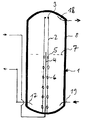
- the total designated 1 hot water tank includes a tank 8, in which, here from the bottom, a hot water supply pipe or loading water feed pipe 4 is guided, which can be connected to the flow of the secondary side of a heat exchanger, which is connected on the primary side to, for example, a solar collector.
- the loading water feed pipe 4 stands vertically and centrally in the tank 8 and ends on one average height, which is determined by the daily hot water consumption level 7.
- the loading water feed pipe 4 is coaxially surrounded by a guide tube 2, which ends in the upper region of the tank 8. Below the outlet of the loading water feed pipe 4, the guide tube 2 has an uppermost ring of holes 5 leading into the tank 8 without non-return flaps or the like.
- the guide tube 2 is provided at the upper end with an opening leading into the tank or an orifice outlet 3, which narrows the outlet relative to the guide tube cross section and is set in cross section in the manner specified below.
- This cross section can be fixed or thermostatically controllable. It is not absolutely necessary for the outlet to be in the end face of the guide tube. An outlet or outlets in the end of the tube wall of a guide tube that is completely closed on the end face are also possible.
- the hot water flow is indicated, via which the heated water is removed from the storage tank, 17 denotes a loading water extraction, via which the water in the storage tank at the lowest temperature is fed to the heat exchanger, and 19 a cold water supply, via which the hot water supply 18 is taken over Water is replaced.
- the loading water feed pipe 4 passes through standing water layers in the guide tube, which can have a lower temperature than the fed hot water, it is advisable to avoid heat losses by providing the feed pipe made of heat-insulating material. It is also expedient to design the guide tube 2 from a material which is poorly conductive in terms of heat.
- the loading water feed pipe 4 is introduced from the side, the problem of crossing colder zones and thus undesired cooling of the warm feed-in can be avoided Water can be avoided.
- An introduction of the loading water feed pipe 4 from above is also conceivable, but then the opposite problem can occur that the cold water fed in cools the hot water already in the reservoir.
- the mode of operation of the stratified tank in question is as follows. It is initially assumed that warm water is supplied via the loading water feed pipe 4, the temperature of which is higher than or equal to that of the water in the tank 8 at the top. Then the water emerging from the loading water feed pipe 4 in the guide tube 2 will rise due to the lift and leave the guide tube 2 only via the mouth outlet 3 located at its upper end.
- the mouth outlet or the outlet opening 3 is to be selected with such a low flow resistance that it is able to discharge the hot water flowing out of the loading water feed pipe 4 out of the guide pipe 2 into the tank 8 alone. If the flow resistance is too great, the inflowing hot water would also find a way through the openings of one or more of the perforated rings 5, 6 located in the lower part of the guide tube 2.
- the outlet at the upper end is selected so that the through the outlet opening (s) 3 at the upper end of the guide tube 2, the amount of water discharged into the tank corresponds to that which is supplied via the loading water feed pipe 4.
- the size of the orifice 3 can be controlled thermostatically, the size of which it has or around which it depends on the expected average flow rate of the heated water. With a few square meters of solar collector area, typical flow rates to be expected are 1 to 2 l / min.
- the density then drops to a greater density than the water standing further up in the guide tube or tank Water in the guide tube from the exit point downwards and leaves the guide tube 2 through one of the perforated rings 5, 6, and the higher the temperature of the water, the higher.
- the process water is stored in layers, layered according to temperatures from top to bottom, so that the undesired mixing of different temperature layers is largely avoided and, in addition, there is no degradation of the hottest zone in the upper part of the tank, so that above the uppermost ring of holes 5 service water is always available at the highest possible temperature.
- the uppermost ring of holes 5 lies below the end of the loading water feed pipe 4, expediently at the daily hot water demand level, because this upper area in the tank is heated up first.
- This daily requirement area is also stratified without there being wreaths of holes along its height, which could not fulfill their function at all, because, if not loaded with water of uniform temperature, it is always charged with cooler water from below.
- the process water feed pipe can be used 4 end approximately at a height of 1.40 m, the number of perforated rings is 6; the number of holes per ring of holes is one of the numbers 1 to 10, preferably 4 or 6.
- the diameter of a hole of a ring of holes 5, 6 is between 20 and 5 mm, preferably 15 and 7 mm, in particular 12 and 8 mm and particularly preferably 10 mm, the latter preferably also with a number of holes per ring of 4.
- the distance between the hole rings is preferably between 300 and 100 mm, preferably 250 to 150 mm, in particular 210 to 190 mm, particularly preferably 200 mm.
- the outlet of the process water feed pipe 4 should be at least about half of such a value, preferably about a whole such value, above the uppermost ring of holes 5.
- the diameter of the outlet opening 3 at the upper end of the guide tube 2 is between 20 and 5 mm, preferably between 15 and 5 mm, in particular 10 and 5 mm, preferably between 9 and 5 mm, very preferably 8 mm.
- the inside diameter of the loading water feed pipe 4 can be 16 mm, that of the guide pipe 2 50 mm. A functional combination for the approx.
- 2 m high tank with loading water feed pipe 4 which ended at a height of approximately 1.40 m had six perforated rings, each with four holes with a diameter of 10 mm at a distance of 200 mm, the uppermost perforated ring 5 approximately 200 mm below the upper end of the feed pipe 4 was.
- the diameter of the outlet opening was 8 mm.
- the loading water feed pipe 4 is designed with an opening not pointing upwards, or if the opening facing upwards is shielded by a type of baffle located at a distance from the opening, then it is ensured that the loading water feed pipe opening is also located near the mouth opening 3 of the guide tube 2 4 (for example with a small daily requirement) is not already conveyed through the outlet opening 3 due to the flow velocity of the water in the feed pipe 4.
Landscapes
- Engineering & Computer Science (AREA)
- Physics & Mathematics (AREA)
- Thermal Sciences (AREA)
- Mechanical Engineering (AREA)
- General Engineering & Computer Science (AREA)
- Heat-Pump Type And Storage Water Heaters (AREA)
- Apparatus For Making Beverages (AREA)
Applications Claiming Priority (2)
| Application Number | Priority Date | Filing Date | Title |
|---|---|---|---|
| DE4119542A DE4119542C1 (enExample) | 1991-06-13 | 1991-06-13 | |
| DE4119542 | 1991-06-13 |
Publications (2)
| Publication Number | Publication Date |
|---|---|
| EP0518369A1 EP0518369A1 (de) | 1992-12-16 |
| EP0518369B1 true EP0518369B1 (de) | 1994-09-28 |
Family
ID=6433884
Family Applications (1)
| Application Number | Title | Priority Date | Filing Date |
|---|---|---|---|
| EP92109944A Expired - Lifetime EP0518369B1 (de) | 1991-06-13 | 1992-06-12 | Schichtspeicher |
Country Status (3)
| Country | Link |
|---|---|
| EP (1) | EP0518369B1 (enExample) |
| AT (1) | ATE112386T1 (enExample) |
| DE (1) | DE4119542C1 (enExample) |
Cited By (1)
| Publication number | Priority date | Publication date | Assignee | Title |
|---|---|---|---|---|
| WO2024144397A1 (en) * | 2022-12-27 | 2024-07-04 | Newton Energy Solutions Holding B.V. | Sensible heat device |
Families Citing this family (11)
| Publication number | Priority date | Publication date | Assignee | Title |
|---|---|---|---|---|
| DE4221668C2 (de) * | 1992-07-02 | 1998-07-16 | Ulrich Dipl Ing Leibfried | Warmwasser-Schichtenspeicher mit Gegenstromwärmetauscher |
| DE4417138C2 (de) * | 1994-05-17 | 1996-04-18 | Alfons Kruck | Warmwasserschichtspeicher |
| DE19752813B4 (de) * | 1997-11-28 | 2008-03-06 | Reha Gmbh Kunststoff-Recycling Und Handel Mit Umweltorientierten Produkten | Warmwasserschichtspeicher |
| DE59808523C5 (de) | 1997-12-15 | 2017-04-20 | Tisun GmbH | Wärmespeicher |
| DE10060259C1 (de) * | 2000-12-04 | 2002-04-18 | Heinz Krokowski | Pufferspeicher |
| FR2837266B1 (fr) * | 2002-03-14 | 2004-06-18 | Dominique Seguy | Ballon d'eau chaude sanitaire muni d'une canne centrale, dispositif de production et de chauffage d'eau chaude sanitaire muni d'un tel ballon et procede associe |
| AT507075B1 (de) | 2008-12-29 | 2010-02-15 | Teufel Arnold | Wärmespeicher |
| IT1398061B1 (it) * | 2010-02-04 | 2013-02-07 | Thermorossi Spa | Dispositivo accumulatore a stratificazione di acqua, particolarmente acqua primaria |
| DE102011103146B4 (de) | 2011-05-25 | 2021-09-30 | Kermi System GmbH | Einströmdämpfer |
| US10912864B2 (en) | 2015-07-24 | 2021-02-09 | Musculoskeletal Transplant Foundation | Acellular soft tissue-derived matrices and methods for preparing same |
| GR20220100295A (el) * | 2022-04-04 | 2023-11-13 | Cardioexpress Υπηρεσιες Τηλεϊατρικης Ανωνυμη Εταιρια, | Συστημα θερμικης διαστρωματωσης υγρου σε δεξαμενη/λεβητα |
Family Cites Families (2)
| Publication number | Priority date | Publication date | Assignee | Title |
|---|---|---|---|---|
| SE402639B (sv) * | 1976-11-12 | 1978-07-10 | Automatik Verme Ventilationsse | Anordning vid ackumuleringstank fer vetska |
| DE3905874A1 (de) * | 1989-02-23 | 1990-08-30 | Solvis Energiesysteme Gmbh | Warmwasserspeicher mit einem von brauchwasser durchstroemten heizkreis mit aussen liegendem heizelement und mit einer ladewechselvorrichtung |
-
1991
- 1991-06-13 DE DE4119542A patent/DE4119542C1/de not_active Expired - Fee Related
-
1992
- 1992-06-12 AT AT92109944T patent/ATE112386T1/de active
- 1992-06-12 EP EP92109944A patent/EP0518369B1/de not_active Expired - Lifetime
Cited By (2)
| Publication number | Priority date | Publication date | Assignee | Title |
|---|---|---|---|---|
| WO2024144397A1 (en) * | 2022-12-27 | 2024-07-04 | Newton Energy Solutions Holding B.V. | Sensible heat device |
| NL2033841B1 (en) * | 2022-12-27 | 2024-07-09 | Newton Energy Solutions Holding B V | Sensible heat device |
Also Published As
| Publication number | Publication date |
|---|---|
| ATE112386T1 (de) | 1994-10-15 |
| DE4119542C1 (enExample) | 1993-01-14 |
| EP0518369A1 (de) | 1992-12-16 |
Similar Documents
| Publication | Publication Date | Title |
|---|---|---|
| EP0518369B1 (de) | Schichtspeicher | |
| DE19782044B3 (de) | Verfahren zum Zugeben und Zuführen von Reaktionsgas und Feststoffen in einen Schmelzofen und ein für diesen Zweck bestimmter mehrfach einstellbarer Brenner | |
| EP0683362B1 (de) | Wärmespeicher | |
| DE2849161A1 (de) | Verfahren und vorrichtung zur speicherung von waermeenergie | |
| DE19743563A1 (de) | Wärmeschichtspeicher | |
| DE10025318C1 (de) | Schichtspeicher | |
| DE29612894U1 (de) | Warmwasserspeicher, insbesondere für Brauchwasser | |
| DE3044079C2 (de) | Warmwasserspeicher | |
| EP0924471B1 (de) | Wärmespeicher | |
| EP1936314B1 (de) | Warmwasser-Schichtspeicher | |
| DE202015101978U1 (de) | Speichertank mit Strömungsleitelement | |
| EP0861985A2 (de) | Vorrichtung zur vertikalen Temperaturschichtung eines Fluids in einem Speicherbehälter | |
| DE19516837C2 (de) | Behälter mit einer Flüssigkeit zur Wärme- oder Kältespeicherung | |
| DE10237771B3 (de) | Warmwasserschichtspeicher | |
| DE1506040B2 (de) | Fluessigkeits-speichererhitzer | |
| DE102015106132A1 (de) | Speichertank mit Strömungsleitelement | |
| DE4306684A1 (de) | Speicherbehälter | |
| DE2912785C3 (de) | Warmwasserbereiter | |
| DE29823740U1 (de) | Vorrichtung zur vertikalen Temperaturschichtung eines Fluids in einem Speicherbehälter | |
| DE10257209B3 (de) | Verteilereinrichtung für eine Warmwasser-Schichtspeichervorrichtung und entsprechende Warmwasser-Schichtspeichervorrichtung | |
| EP0797053B1 (de) | Verteiler für einen Flüssigkeitsstrom in einer Heizungsanlage | |
| DE1506040C3 (de) | Flüssigkelts-Speichererhitzer | |
| DE102018004352A1 (de) | Entnahme-/Abgabevorrichtung und Verfahren zur Entnahme oder Abgabe eines wärmetragenden Fluids aus einem Speicherbehälter oder in einen Speicherbehälter | |
| DE202010006896U1 (de) | Sammler-Verteiler-Einheit mit hydraulischer Weiche | |
| EP0049503B1 (de) | Warmwasser-Heizungsanlage mit Wärmepumpe und Wärmepuffer |
Legal Events
| Date | Code | Title | Description |
|---|---|---|---|
| PUAI | Public reference made under article 153(3) epc to a published international application that has entered the european phase |
Free format text: ORIGINAL CODE: 0009012 |
|
| AK | Designated contracting states |
Kind code of ref document: A1 Designated state(s): AT BE CH DE DK ES FR GB GR IT LI LU MC NL PT SE |
|
| 17P | Request for examination filed |
Effective date: 19921218 |
|
| 17Q | First examination report despatched |
Effective date: 19930504 |
|
| RBV | Designated contracting states (corrected) |
Designated state(s): AT BE CH DK ES FR GB GR IT LI LU MC NL PT SE |
|
| REG | Reference to a national code |
Ref country code: DE Ref legal event code: 8566 |
|
| GRAA | (expected) grant |
Free format text: ORIGINAL CODE: 0009210 |
|
| AK | Designated contracting states |
Kind code of ref document: B1 Designated state(s): AT BE CH DK ES FR GB GR IT LI LU MC NL PT SE |
|
| PG25 | Lapsed in a contracting state [announced via postgrant information from national office to epo] |
Ref country code: IT Free format text: LAPSE BECAUSE OF FAILURE TO SUBMIT A TRANSLATION OF THE DESCRIPTION OR TO PAY THE FEE WITHIN THE PRE;WARNING: LAPSES OF ITALIAN PATENTS WITH EFFECTIVE DATE BEFORE 2007 MAY HAVE OCCURRED AT ANY TIME BEFORE 2007. THE CORRECT EFFECTIVE DATE MAY BE DIFFERENT FROM THE ONE RECORDED.SCRIBED TIME-LIMIT Effective date: 19940928 Ref country code: ES Free format text: THE PATENT HAS BEEN ANNULLED BY A DECISION OF A NATIONAL AUTHORITY Effective date: 19940928 Ref country code: GR Free format text: LAPSE BECAUSE OF FAILURE TO SUBMIT A TRANSLATION OF THE DESCRIPTION OR TO PAY THE FEE WITHIN THE PRESCRIBED TIME-LIMIT Effective date: 19940928 Ref country code: DK Effective date: 19940928 Ref country code: FR Effective date: 19940928 Ref country code: BE Effective date: 19940928 Ref country code: NL Effective date: 19940928 Ref country code: MC Free format text: LAPSE BECAUSE OF NON-PAYMENT OF DUE FEES Effective date: 19940928 Ref country code: GB Effective date: 19940928 |
|
| REF | Corresponds to: |
Ref document number: 112386 Country of ref document: AT Date of ref document: 19941015 Kind code of ref document: T |
|
| PG25 | Lapsed in a contracting state [announced via postgrant information from national office to epo] |
Ref country code: SE Effective date: 19941228 Ref country code: PT Effective date: 19941228 |
|
| EN | Fr: translation not filed | ||
| NLV1 | Nl: lapsed or annulled due to failure to fulfill the requirements of art. 29p and 29m of the patents act | ||
| GBV | Gb: ep patent (uk) treated as always having been void in accordance with gb section 77(7)/1977 [no translation filed] |
Effective date: 19940928 |
|
| PG25 | Lapsed in a contracting state [announced via postgrant information from national office to epo] |
Ref country code: LU Free format text: LAPSE BECAUSE OF NON-PAYMENT OF DUE FEES Effective date: 19950630 |
|
| PLBE | No opposition filed within time limit |
Free format text: ORIGINAL CODE: 0009261 |
|
| STAA | Information on the status of an ep patent application or granted ep patent |
Free format text: STATUS: NO OPPOSITION FILED WITHIN TIME LIMIT |
|
| 26N | No opposition filed | ||
| PGFP | Annual fee paid to national office [announced via postgrant information from national office to epo] |
Ref country code: AT Payment date: 19980925 Year of fee payment: 7 |
|
| PGFP | Annual fee paid to national office [announced via postgrant information from national office to epo] |
Ref country code: CH Payment date: 19981130 Year of fee payment: 7 |
|
| PG25 | Lapsed in a contracting state [announced via postgrant information from national office to epo] |
Ref country code: AT Free format text: LAPSE BECAUSE OF NON-PAYMENT OF DUE FEES Effective date: 19990612 |
|
| PG25 | Lapsed in a contracting state [announced via postgrant information from national office to epo] |
Ref country code: CH Free format text: LAPSE BECAUSE OF NON-PAYMENT OF DUE FEES Effective date: 19990630 Ref country code: LI Free format text: LAPSE BECAUSE OF NON-PAYMENT OF DUE FEES Effective date: 19990630 |
|
| REG | Reference to a national code |
Ref country code: CH Ref legal event code: PL |