EP0797053B1 - Verteiler für einen Flüssigkeitsstrom in einer Heizungsanlage - Google Patents
Verteiler für einen Flüssigkeitsstrom in einer Heizungsanlage Download PDFInfo
- Publication number
- EP0797053B1 EP0797053B1 EP97810151A EP97810151A EP0797053B1 EP 0797053 B1 EP0797053 B1 EP 0797053B1 EP 97810151 A EP97810151 A EP 97810151A EP 97810151 A EP97810151 A EP 97810151A EP 0797053 B1 EP0797053 B1 EP 0797053B1
- Authority
- EP
- European Patent Office
- Prior art keywords
- valve
- distributor
- temperature
- thermostat
- liquid
- Prior art date
- Legal status (The legal status is an assumption and is not a legal conclusion. Google has not performed a legal analysis and makes no representation as to the accuracy of the status listed.)
- Expired - Lifetime
Links
Images

Classifications
-
- F—MECHANICAL ENGINEERING; LIGHTING; HEATING; WEAPONS; BLASTING
- F24—HEATING; RANGES; VENTILATING
- F24D—DOMESTIC- OR SPACE-HEATING SYSTEMS, e.g. CENTRAL HEATING SYSTEMS; DOMESTIC HOT-WATER SUPPLY SYSTEMS; ELEMENTS OR COMPONENTS THEREFOR
- F24D3/00—Hot-water central heating systems
- F24D3/10—Feed-line arrangements, e.g. providing for heat-accumulator tanks, expansion tanks ; Hydraulic components of a central heating system
- F24D3/1058—Feed-line arrangements, e.g. providing for heat-accumulator tanks, expansion tanks ; Hydraulic components of a central heating system disposition of pipes and pipe connections
- F24D3/1066—Distributors for heating liquids
-
- F—MECHANICAL ENGINEERING; LIGHTING; HEATING; WEAPONS; BLASTING
- F24—HEATING; RANGES; VENTILATING
- F24D—DOMESTIC- OR SPACE-HEATING SYSTEMS, e.g. CENTRAL HEATING SYSTEMS; DOMESTIC HOT-WATER SUPPLY SYSTEMS; ELEMENTS OR COMPONENTS THEREFOR
- F24D19/00—Details
- F24D19/10—Arrangement or mounting of control or safety devices
- F24D19/1006—Arrangement or mounting of control or safety devices for water heating systems
- F24D19/1009—Arrangement or mounting of control or safety devices for water heating systems for central heating
- F24D19/1015—Arrangement or mounting of control or safety devices for water heating systems for central heating using a valve or valves
- F24D19/1024—Arrangement or mounting of control or safety devices for water heating systems for central heating using a valve or valves a multiple way valve
- F24D19/103—Arrangement or mounting of control or safety devices for water heating systems for central heating using a valve or valves a multiple way valve bimetal operated
-
- F—MECHANICAL ENGINEERING; LIGHTING; HEATING; WEAPONS; BLASTING
- F24—HEATING; RANGES; VENTILATING
- F24D—DOMESTIC- OR SPACE-HEATING SYSTEMS, e.g. CENTRAL HEATING SYSTEMS; DOMESTIC HOT-WATER SUPPLY SYSTEMS; ELEMENTS OR COMPONENTS THEREFOR
- F24D3/00—Hot-water central heating systems
- F24D3/12—Tube and panel arrangements for ceiling, wall, or underfloor heating
-
- F—MECHANICAL ENGINEERING; LIGHTING; HEATING; WEAPONS; BLASTING
- F24—HEATING; RANGES; VENTILATING
- F24D—DOMESTIC- OR SPACE-HEATING SYSTEMS, e.g. CENTRAL HEATING SYSTEMS; DOMESTIC HOT-WATER SUPPLY SYSTEMS; ELEMENTS OR COMPONENTS THEREFOR
- F24D11/00—Central heating systems using heat accumulated in storage masses
- F24D11/002—Central heating systems using heat accumulated in storage masses water heating system
- F24D11/003—Central heating systems using heat accumulated in storage masses water heating system combined with solar energy
-
- Y—GENERAL TAGGING OF NEW TECHNOLOGICAL DEVELOPMENTS; GENERAL TAGGING OF CROSS-SECTIONAL TECHNOLOGIES SPANNING OVER SEVERAL SECTIONS OF THE IPC; TECHNICAL SUBJECTS COVERED BY FORMER USPC CROSS-REFERENCE ART COLLECTIONS [XRACs] AND DIGESTS
- Y02—TECHNOLOGIES OR APPLICATIONS FOR MITIGATION OR ADAPTATION AGAINST CLIMATE CHANGE
- Y02B—CLIMATE CHANGE MITIGATION TECHNOLOGIES RELATED TO BUILDINGS, e.g. HOUSING, HOUSE APPLIANCES OR RELATED END-USER APPLICATIONS
- Y02B10/00—Integration of renewable energy sources in buildings
- Y02B10/20—Solar thermal
-
- Y—GENERAL TAGGING OF NEW TECHNOLOGICAL DEVELOPMENTS; GENERAL TAGGING OF CROSS-SECTIONAL TECHNOLOGIES SPANNING OVER SEVERAL SECTIONS OF THE IPC; TECHNICAL SUBJECTS COVERED BY FORMER USPC CROSS-REFERENCE ART COLLECTIONS [XRACs] AND DIGESTS
- Y02—TECHNOLOGIES OR APPLICATIONS FOR MITIGATION OR ADAPTATION AGAINST CLIMATE CHANGE
- Y02B—CLIMATE CHANGE MITIGATION TECHNOLOGIES RELATED TO BUILDINGS, e.g. HOUSING, HOUSE APPLIANCES OR RELATED END-USER APPLICATIONS
- Y02B10/00—Integration of renewable energy sources in buildings
- Y02B10/70—Hybrid systems, e.g. uninterruptible or back-up power supplies integrating renewable energies
-
- Y—GENERAL TAGGING OF NEW TECHNOLOGICAL DEVELOPMENTS; GENERAL TAGGING OF CROSS-SECTIONAL TECHNOLOGIES SPANNING OVER SEVERAL SECTIONS OF THE IPC; TECHNICAL SUBJECTS COVERED BY FORMER USPC CROSS-REFERENCE ART COLLECTIONS [XRACs] AND DIGESTS
- Y02—TECHNOLOGIES OR APPLICATIONS FOR MITIGATION OR ADAPTATION AGAINST CLIMATE CHANGE
- Y02B—CLIMATE CHANGE MITIGATION TECHNOLOGIES RELATED TO BUILDINGS, e.g. HOUSING, HOUSE APPLIANCES OR RELATED END-USER APPLICATIONS
- Y02B30/00—Energy efficient heating, ventilation or air conditioning [HVAC]
Definitions
- the present invention relates to a distributor for a liquid flow in a heating system according to the preamble of claim 1.
- heating circuits in practice today known that in addition to an energy source and the necessary consumer equipment, usually radiators, also include an energy store, thanks to which the generated or supplied by the energy source Energy can be stored when the need is smaller, so it can be used again later at a cheaper time. So it is known that, for example, in electrically heated systems in which the low tariff times should be better used, and especially in Plants with solar panels use the energy during hot times arises during the day during which the heating energy requirement is up front lower, storage of this energy is required during these times is later during the colder times of the day or during the At night, or in certain large capacity systems, even during the cooler ones Seasons can be reused.
- a storage system for thermal energy in combination with an energy source is e.g. known from DE-A-2700822.
- the heat transfer fluid usually water, flows through the coil from the center to the outer end of the pipe coil.
- the heat losses can be kept as small as possible be because when the stored heat is released from the Store the cold heat transfer fluid in the opposite direction the memory is sent, that is from the outer end of the queue to the Center, which thanks to the flow against the direction of the temperature gradient in the storage mass of the storage, as much energy as possible usable heat is recovered, the heat losses minimal being held.
- This system can be further improved in application practice by instead of a single coil of heat transfer fluid is flowed outwards from the center during storage, and from the outside to the inside during the recovery of the stored Heat, at least three concentric in a substantially horizontal plane arranged coils are provided, the first of Center is fed while the other two start where the previous one ends or ends where the next one begins.
- first coil the warmest liquid circulates while in the pipe coils further out, following the first one are referred to as “second”, “third”, etc., which circulates colder liquid.
- second the warmest liquid circulates while in the pipe coils further out, following the first one are referred to as "second”, "third”, etc., which circulates colder liquid.
- the aim of the present invention is therefore to provide a distributor for a liquid flow in to propose a heating system with an energy source and with an energy store, the at least three and preferably four or more separate circuits comprises, whereby the distributor ensures that in the individual coils, whose energy in the storage decreases from the inside out because the coldest liquid flow systematically to the outermost pipe coil or to the outermost separate Circuit while the warmest is directed to the innermost coil, the transition from one pipe run to the other if possible in terms of temperature must be done exactly.
- a liquid flow manifold according to the preamble of claim 1 thanks to the properties according to the characterizing part of claim 1.
- an energy storage system which consists of four separate circuits exists, while the manifold comprises three three-way valves.
- the number of used Circuits can in principle be of any size, however under Taking into account the available space, the installation costs, the performance achieved, etc. Is essential in the context of present invention merely that the number of circuits is greater than two and the number of three-way valves used always smaller than that which should be separate circuits.
- the number of four circuits with three three-way valves in most practical Use cases is an optimal solution.
- the three-way valves are equipped with an expansion thermostat, which reacts to the temperature of the liquid flowing through.
- an expansion thermostat which reacts to the temperature of the liquid flowing through.
- the system is a solar energy system is whose energy source comes from an array of solar panels on the roof and / or on the walls, and with an energy store, which comprises at least three separate circuits in which the Liquid circulates in separate but adjacent temperature ranges.
- This field of application proves to be ideal for the one according to the invention
- Distributor, especially in such systems of several, of liquid flows at circulating circuits at different temperature levels optimal use is made, in particular if, as claimed in claim 7, with separate, in the ground under the building in the form of concentric Spiral circuits, one next to the other are arranged in a horizontal plane.
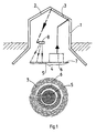
- Fig. 1 is a schematic, top in elevation and bottom in plan, one characteristic application of the distributor according to the invention shown. This is its use in the context of a solar heating system for a normal house, for example for a single family house.
- the building structure is designated by 1, in the roof 2 of which an energy source element is installed, for example a conventional solar collector 3.
- the heat is absorbed by means of a heat transfer fluid, for example water, which circulates in a tube system.
- a pipe system is arranged in the ground under the house, which as a whole forms the energy store 4.
- the energy store 4 comprises three separate circuits 5, 6 and 7, the innermost circuit 5 of which consists of a pipe coil laid out in a spiral in a horizontal plane at a depth of at least 2 m below the floor of the house.
- One end of the pipe spiral is at the extreme point of the spiral and the other end is at the center.
- the hot liquid which comes from the energy source 3 mounted on the roof 2, flows through the pipe spiral of the circuit 5 from the outside in, ie from its outermost turn to the center of the spiral. It is known that this innermost circuit must be heated by the hottest liquid coming from the heat source so that the heat losses can be kept as small as possible.
- the temperature t 5 of the liquid flowing through this circuit is typically above 35 ° C, ie t 5 > 35 ° C.
- the second spiral which forms the second separate circuit 6, is formed by a likewise spiral-shaped pipeline, which is essentially coplanar with the circuit 5 and is arranged outside the spiral: this second circuit therefore begins at the outermost point of the spiral 6 and ends in the vicinity of the internal circuit 5.
- This second circuit is also flowed through from outside to inside by liquid from the energy source, the temperature of which lies between two defined limits, the upper one of which is lower than that on which the separate circuit 5 is fed , ie below 35 ° C in the example described here.
- the circuit 6 is fed with liquid, the temperature t 6 of which should be, for example, one step in the range from 15 ° C. ⁇ t 6 ⁇ 35 ° C.
- the last separate circuit 7, the outermost one, is also formed by a coplanar spiral arranged with the above-mentioned circuits 5 and 6, which is outside the spiral of the circuit 6: the tube spiral 7 begins at the outermost point and ends in the region of the spiral of the separated one Circuit 6.
- the liquid is conducted from the energy source when it is coldest and the minimum temperature, namely 15 ° C. in the example described here, is no longer reached.
- the temperature t 7 of the liquid circulating in the circuit 7 must satisfy the condition t 7 ⁇ 15 ° C. in the example described here. So if the liquid in the heat source is heated to less than 15 ° C, it must be directed into the outermost spiral that forms the circuit 7.
- FIG. 1 The distributor for a liquid flow 8 in a system according to FIG. 1 is shown in more detail in Fig. 2, in which two thermostatic valves 9 and 10 of the same type are shown, so that the description of the valve 9 also applies to all details of the valve 10.
- the valve 9 comprises a valve body 11 which is made, for example, of hot-pressed Brass is made.
- the valve body 11 has three openings, it is therefore a three-way valve: one inlet 12 and two outlets 13 and 14.
- the outlets 13 and 14 can alternately through the in a his two end positions brought slide 15 are blocked; in the Fig. 2 shows the slide 15 in its lower end position, which also is at rest, and in which is the liquid flowing through the chamber 16 flows thanks to the thermostat 17 to the outlet 14.
- the thermostat is connected with its pin 18 in the valve body 11 of the valve 9 Bush 19 attached by means of a threaded cover 22.
- a compression spring 20 By means of a compression spring 20, the pin is constantly with the lower stop 21 of the sleeve 19 held in contact, the pin 18 and the Bush 19 usually form a unit.
- the thermostat 17 of the valve 9 is a thermostat which is able to move the slide 15 from its lower rest position shown in FIG. 2 to its upper position in abutment against the threaded cover 21 (which in the sense of a Example in the case of the valve 10 is shown, which is constructed exactly the same as the valve 9), the response range of the temperature fluctuation of the liquid flow being kept extremely narrow.
- Such precise thermostats are commercially available today and are generally used.
- the thermostat 17 shown in FIG. 1, for example, is provided to move the slide 15 from one end position to the other when the temperature changes between 33 ° C. and 35 ° C., ie within a temperature range of only 2 ° C.
- the slide 15 remains in its lower rest position shown in FIG. 2 up to a temperature of 33 ° C.
- the thermostat moves the slider 15 into its uppermost end position at the stop against the threaded cover 22 when the substance reacting to heat expands. If the liquid temperature rises above 35 ° C, it passes through the Inlet 12 of the valve 9 liquid entering from the chamber 25 of the valve 9 and leaves the valve 9 through the outlet 13, through which only a liquid flow can pass, the temperature thereof (apart from the short period during which the slide valve 15 is at a temperature is shifted upward between 33 ° C. and 35 ° C., and during which the liquid can pass both through the outlet 13 and through the inlet of the valve 10, as will be described in the following) is above 35 ° C.
- the outlet 13, in the arrangement of the separate circuit as shown in FIG. 1, is connected to the innermost circuit 5, which is why the temperature of the liquid emerging from the outlet 13 is designated t 5 , for the t 5 > 35 ° C applies.
- valve 10 The three-way valves 9 and 10 are complete for better understanding same elements with the same reference numerals, those of the valve are additionally marked with an apostrophe.
- the function of the valve 10 corresponds exactly to that of the valve described 9, wherein the valve 10 is equipped with a thermostat 17 ', the Brings slide 15 'into its position, in which the lower chamber 25' is shut off and the upper chamber 16 'are open as long as the liquid flow Minimum temperature, which is set at 15 ° C in the example described, has not yet reached, and pushes the slide 15 'into its upper chamber 16 'barrier position (where the expressions below and above refer to the position relative to the inlet 12 'of the valve 10', so that in FIG.
- both chambers stand 16 'and 25' open, so that the liquid in both one and the other chamber can enter, and thus both through the outlet 13 ' can also flow through the outlet 14 'of the valve 10.
- both the separate circuit 6 (which is shown in FIG. 1 as the middle circuit) and the separate circuit 7.
- a value which is only from selected type of thermostat 17 or 17 ') is thus achieved that from the outlet 13' of the valve 10, which is in communication with the chamber 25 ', the liquid coming from the heat source 3 (via the corresponding connection) into the middle coil 6 of the heat accumulator passes as soon as its temperature t 6 satisfies the condition 35 ° C ⁇ t 6 ⁇ 35 ° C, while liquid emerges from the outlet 14 'of the valve 10 in order to pass through the separate outermost circuit 7 of the heat accumulator as soon as the liquid temperature the intended minimum value, in the case of the example described t 7 ⁇ 15 ° C.
- the thermostat 17 'begins to react at 13 ° C and the slide 15 begins to move from the position in which the chamber 25' is closed and the chamber 16 'is open to the opposite position to the circuit 6 already at the temperature of 13 ° C liquid, since liquid with a temperature between 13 ° C and 15 ° C already exits both through the outlet 14 'and through the outlet 13' during the switching phase of the valve 10.
- a characteristic feature of the present invention is that the slide 15, 15 'of the valves 9 and 10, respectively, in the most general application 2 - as well as the analog slide valve in the more complex embodiment to be described below in Heat storage systems with more than three separate circuits - use find themselves from their position in which an outlet 13 or 13 'is closed are in a position in which the other outlet 14 or 14 'is closed, within the smallest possible range of change their working temperature of 3 ° C and preferably as described in Case of the example shown in Figures 1 and 2, of 2 ° C.
- the distributor for a liquid flow as it is based on the embodiment 1 and 2, for supplying an energy store, which comprises three separate circuits 5, 6, 7 works as follows:
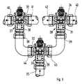
- FIG. 3 shows a first preferred variant of the distributor for the liquid flow shown according to the present invention, which differs from the previously described with reference to Figures 1 and 2 only differs in that it also has another three-way valve, i.e. three instead of two, and that it can thus feed an energy store, which comprises four separate circuits instead of just three.
- the arrangement of Four separate circuits in the memory has been used for many practical applications proven ideal, but within the scope of the present invention there is no limit to the number of separate circuits that can be foreseen is. The limits only result from the economic viability of one such system, the more expensive the greater the number of used separate circuits is chosen, even if their efficiency is always can still increase.
- the three three-way valves 26, 27 and 28 are of the type shown in FIG. 2 the same structure and function as those already described Valves 9 and 10. It goes without saying that the present Invention does not apply to the use of three-way valves described Is restricted, the advantage of which can be seen in the fact that they with a single pressed part made of brass in a minimal number of work steps can be produced.
- Other types of three-way valves which also have an inlet and two outlets that alternate can be opened or closed by means of a slide, the one with high sensitivity to the temperature of the liquid flowing through reacts so that the slide due to a very low temperature deviation (from according to the invention not more than 3 ° C) from an end position to the other (i.e. from a position in which one of the outlets is closed and the other one is open) can be moved easily in Within the scope of the present invention can also be considered.
- expansion thermostatic valves are analogous to what has already been said that with reference to FIGS. 1 and 2 described embodiment and also in the with reference to the Fig. 3 described embodiment, within the scope of the present invention preferred as they use any type of external energy supply no need to switch the valves.
- the present Invention for example, with the help of electromagnetic, temperature-controlled Three-way valves can be realized with a temperature sensor are provided, the temperature of the liquid flowing through measures and initiates the switching of the valve as soon as one to the advance specified switching temperature is reached.
- the valve 26 is connected via its inlet 35 to the energy source 3 (FIG. 1), while its two outlets 36 and 37 with the inlet 38 of the Valve 27 or are connected to the inlet 39 of the valve 28.
- the outlets 40 and 41 of the valve 27, or 42 and 43 of the valve 28, are each with one of the four separate heat storage circuits (not shown) connected, which is in principle the same as the heat accumulator 4, according to 1 build memory, but with four instead of three is equipped with separate "concentric" circuits.
- the distributor for a liquid flow according to FIG. 3 works analogously to the embodiment described with reference to Figures 1 and 2.
- Liquid flows with the outlet 40 of the valve 27 a temperature below 15 ° C
- liquid flows from the outlet 41 of the valve 27 with a temperature between 15 and 25 ° C (apart from the short Time period during which the valve is switched over during which the liquid from both outlets of the Valve can exit) while from the outlets 42 and 43 of the valve 28 liquid with a temperature between 25 and 35 ° C or above 35 ° C exit.
- each of the valves 9, 10, 26, 27 and 28 equipped with an adjustment device by means of which the working temperature of each valve can be finely adjusted.
- the expansion thermostatic valves are those in the figures 1, 2 and 3 shown type, one within the scope of the present Invention preferred valve type represent the factory to a certain Response temperature range, as in the course of the description of the exemplary embodiments was declared, delivered by default. However, it is preferable that each valve has its own temperature setting system is used to fine-tune the response temperature can to the valve the practical operating conditions of the distributor to be able to adapt better.
- a suitable one for the valve 9, 10, 26, 27 or 28 Fine adjustment system is shown in the sense of an example in FIG. 2.
- the sleeve 19, in which the pin 18 of the thermostat 17 is seated, is on the threaded lid 22 attached, which in turn in Valve body 11 is screwed in by means of a thread 46, and the further is provided with a sealing sealing ring.
- the box 19 screwed more or less far into the cover 22 by means of the square nut 48 this allows the compression spring 49 to move upwards onto the Thermostats 17 pressure can be changed slightly, so that the Movement of the slide 15 from its lower stop position in the Upper stop position affects the required force of the thermostat 17 becomes.
- This also influences the working temperature of the thermostat 17, in which he the slider 15 depending on the force with which this in its rest position (shown on valve 9 in FIG. 2) against his stop is pressed, begins to move.
- the present invention is related to a solar heating system with an energy storage located in the ground under Described with reference to the figures, the several separate Circles include, each with liquid of a precisely determined temperature be fed.
Landscapes
- Engineering & Computer Science (AREA)
- Physics & Mathematics (AREA)
- Thermal Sciences (AREA)
- Chemical & Material Sciences (AREA)
- Combustion & Propulsion (AREA)
- Mechanical Engineering (AREA)
- General Engineering & Computer Science (AREA)
- Temperature-Responsive Valves (AREA)
- Heating, Cooling, Or Curing Plastics Or The Like In General (AREA)
- Quick-Acting Or Multi-Walled Pipe Joints (AREA)
- Steam Or Hot-Water Central Heating Systems (AREA)
Description
- Fig. 1 eine schematische Darstellung im Grundriss und in einer Seitenansicht einer Solar-Heizungsanlage mit Erdwärmespeicher zur Erklärung einer typischen Anwendung des erfindungsgemässen Verteilers;
- Fig. 2 ein Verteiler für einen Flüssigkeitsstrom mit zwei Ventilen entsprechend der Erfindung, mit einem Einlass und drei Auslässen, d.h. ein Verteiler zur Beschickung von drei getrennten Kreisläufen;
- Fig. 3 eine ähnliche Darstellung wie in der Fig. 2, aber mit drei miteinander verbundenen Ventilen, die einen Verteiler mit einem Einlass und mit vier Auslässen zur Beschickung von vier getrennten Kreisläufen bilden.
- einfach konstruiert, wartungsfrei und kostengünstig sein muss,
- eine möglichst genaue Trennung sicherstellen muss, nämlich zwischen zwei aufeinanderfolgende Kreisläufen innerhalb genau festgelegter Temperaturbereichen der Flüssigkeit. Als Grössenordnung für diese Bedingung ist etwa 2°C vorzugeben, was heute mit Hilfe bekannter modernster Ausdehnungs-Thermostaten erreicht werden kann, deren grosser Vorteil darin besteht, dass sie ohne äussere Energieversorgung funktionieren.
- Der Schieber 15 des Ventils 9 sperrt die Kammer 25 ab und hält die Kammer 16 offen, da sich der Thermostat 17 in seiner "eingezogenen" Stellung befindet. Der Flüssigkeitsstrom fliesst vom Einlass 12 zum Auslass 14 und zum Einlass 12' des Ventils 10. Auch der Schieber 15' des Ventils 10 befindet sich in der Stellung, die der "eingezogenen" Stellung des Thermostaten 17' entspricht, so dass der Schieber 15' die Kammer 25' des Ventils 10 geschlossen und die Kammer 16' offen hält. Die Flüssigkeit fliesst daher durch die Kammer 16' und durch den Auslass 14', an den der äusserste getrennte Speicherkreislauf 7 angeschlossen ist. Die Flüssigkeit zirkuliert also durch die äusserste Rohrschlange und gibt die Wärme an das umgebende Erdreich ab.
- Sobald bei weiterem Temperaturanstieg der Flüssigkeit im Sonnenkollektor 3 die Temperatur von 13°C überschreitet, verschiebt der für den Reaktionstemperaturbereich von 13°C bis 15°C gewählte und geeichte Thermostat 17' den Schieber 15' aus seiner bisherigen Stellung in seine andere Endstellung, nämlich in die "ausgefahrene" Stellung des Thermostaten 17', in welcher die Kammer 25' offen steht und die Kammer 16' abgesperrt ist. Diese Verschiebung des Thermostaten erfolgt gemäss der Erfindung innerhalb eines Temperaturbereichs von höchstens 3°C. im beschriebenen Beispiel erfolgt die Verschiebung des Schiebers innerhalb eines Temperatur-Schwankungsbereichs von 3°C, d.h. zwischen 13°C und 15°C, so dass bei einer Temperatur von 15°C an der gesamte Flüssigkeitsstrom durch den Auslass 13' des Ventils 10 und in den getrennten Kreislauf 6 des Energiespeichers fliesst, wobei er seine Energie an den ringförmigen mittleren Bereich des Speichers abgibt. Diese Phase dauert an, solange die Temperatur der Flüssigkeit unter 33°C bleibt.
- Sobald bei weiterer Fortsetzung der Erwärmung der Flüssigkeit im Sonnenkollektor 3 die Temperatur von 33°C erreicht hat, verschiebt der für einen Reaktionsbereich zwischen 33°C und 35°C gewählte und geeichte Thermostat 17 den Schieber 15 des Ventils 9 aus seiner Stellung in der die Kammer 25 abgesperrt und die Kammer 16 geöffnet sind - wobei diese Stellung der "eingezogenen" Stellung des Thermostaten 17 entspricht - in die entgegengesetzte Stellung, in welcher die Kammer 16 geöffnet wird. Die Flüssigkeit beginnt bei einer Temperatur zwischen 33°C und 35°C auch durch den Auslass 13 zu fliessen und durch den innersten getrennten Kreislauf 5. Die am meisten erwärmte Flüssigkeit sammelt sich also im innersten Teil des Wärmespeichers. Von dieser Temperatur an aufwärts fliesst die erwärmte Flüssigkeit daher immer in den innersten Kreislauf 5 und speichert seine Wärme in den entsprechenden Bereich des Erdreichs ein. Die Wiedergewinnung von Wärme aus dem Wärmespeicher, d.h. aus dem Erdreich, erfolgt einfach dadurch, dass die Flüssigkeit in umgekehrter Reihenfolge und in umgekehrter Richtung durch die getrennten Kreisläufe geschickt wird, beginnend mit der wärmsten Flüssigkeit des innersten Kreislaufs hin zur kälteren Flüssigkeit der äusseren Kreisläufe. Die Ventile 9 und 10 wechseln dabei automatisch von ihrer "ausgefahrenen" in die "eingefahrene" Stellung, wie bereits beschrieben, wenn die Temperatur der Flüssigkeit in den Reaktions-Temperaturbereich mit den bei den einzelnen Thermostaten genannten Grenztemperaturen absinkt.
Claims (7)
- Verteiler für einen Flüssigkeitsstrom in einer Heizungsanlage mit einer Energiequelle (3) und einem Energiespeicher (4), der aus mindestens drei getrennten Kreisläufen (5, 6, 7) besteht, in welchen die Flüssigkeit mit voneinander getrennten, aber einander benachbarten Temperaturbereichen zirkuliert,
dadurch gekennzeichnet, dass
der Verteiler für den Flüssigkeitsstrom Dreiwegventile in einer Anzahl, kleiner um eine Einheit gegenüber der Anzahl der getrennten Kreisläufe, umfasst (9, 10, 26, 27, 28), von denen jedes einen Einlass (12, 35) und zwei Auslässe (13, 14; 40, 41, 42, 43) umfasst und mit einem Schieber (15, 32, 33, 34) ausgerüstet ist, der wechselweise den einen Auslass absperren und den anderen offen halten kann, oder umgekehrt,
wobei ein erstes Ventil (9, 26) über seinen Einlass (14, 44) mit der Energiequelle (3) verbunden ist, während einer seiner Auslässe (14; 44) mit dem Einlass eines zweiten Ventils (10; 27) verbunden ist und der andere Auslass (13; 45) mit einem der getrennten Kreisläufe (5, 6, 7) des Energiespeichers (3) verbunden ist, und wobei das zweite Ventil (10; 27) über seine zwei Auslässe (13', 14'; 40, 41) mit einem zweiten bzw. dritten getrennten Kreislauf des Speichers verbunden ist und wobei jedes der Ventile (9, 10; 26, 27, 28) mit einem Thermostaten (17, 17'; 29, 30, 31) ausgerüstet ist, der den entsprechenden Schieber (15, 15'; 29, 30, 31) in solcher Weise betätigt, dass er diesen aus der Stellung, in der einer der Auslässe (13, 13'; 40, 42, 44) abgesperrt ist, in die Stellung verschiebt, in welcher der andere Auslass (14, 14'; 41, 43, 45) abgesperrt ist, sobald die Temperatur in seinen Arbeitsbereich von weniger als 3°C und vorzugsweise von 2°C zu liegen kommt. - Verteiler für einen Flüssigkeitsstrom in Verbindung mit einem Energiespeicher, dadurch gekennzeichnet, dass der Energiespeicher aus vier getrennten Kreisläufen besteht, und dass der Verteiler für den Flüssigkeitsstrom drei Dreiwegventile (26, 27, 28) umfasst, wobei ein erstes Ventil (26) über seinen Einlass mit der Energiequelle (3) verbunden ist und seine beiden Auslässe mit dem Einlass des zweiten Ventils und jenem des dritten Ventils (28) verbunden sind, und wobei die Auslässe des zweiten Ventils (27) und des dritten Ventils (28) je mit einem der getrennten Kreisläufe des Speichers verbunden sind,
wobei die Arbeitstemperatur des Thermostaten (29) des ersten Ventils (26) höher als die Arbeitstemperatur des Thermostaten (30) des zweiten Ventils (27) und tiefer als die Arbeitstemperatur des Thermostaten (31) des dritten Ventils (28) liegt, wobei
die getrennten Kreisläufe (5,6,7) von im Erdreich unter dem Gebäude ausgelegten Rohrschlangen gebildet werden, wobei die erste Rohrschlange (5), die von der wärmsten Flüssigkeit durchströmt ist und sich in einer horizontalen Ebene, vom Zentrum ausgehend, als Spirale um sich selbst windet, und die zweite Rohrschlange (6), die den zweiten, gegenüber der ersten Rohrschlange (5) weniger warmen, aber gegenüber jener der dritten (7) wärmeren Flüssigkeit durchströmten Speicherkreislauf bildet, in der gleichen horizontalen Ebene ausgelegt ist, und
wobei alle weiteren Speicherkreisläufe auch von spiralförmigen Rohrschlangen gebildet werden, die jeweils in der gleichen Ebene um die vorhergehende Rohrschlange gewunden sind. - Verteiler für einen Flüssigkeitsstrom gemäss dem Anspruch 2,
dadurch gekennzeichnet, dass
die Arbeitstemperatur des Thermostaten (29) des ersten Ventils (26) zwischen 23°C und 25°C liegt, die Arbeitstemperatur des Thermostaten (30) des zweiten Ventils (27) zwischen 13°C und 15°C liegt und die Arbeitstemperatur des Thermostaten (31) des dritten Ventils (28) zwischen 33°C und 35°C liegt - Verteiler für einen Flüssigkeitsstrom gemäss dem Anspruch 1,
dadurch gekennzeichnet, dass
die Dreiwegventile (9, 10; 26, 27, 28) mit Ausdehnungs-Thermostaten (17, 17'; 29, 30, 31) ausgerüstet sind, die auf die Temperatur der durchströmenden Flüssigkeit reagieren. - Verteiler für einen Flüssigkeitsstrom gemäss dem Anspruch 1,
dadurch gekennzeichnet, dass
jedes der Dreiwegventile (9, 10; 26, 27, 28) mit einer Einstellvorrichtung versehen ist, mittels welcher die Arbeits-Temperatur angepasst werden kann. - Anwendung des Verteiler für einen Flüssigkeitsstrom gemäss einem der vorhergehenden Ansprüche,
dadurch gekennzeichnet, dass
die Heizungsanlage eine Sonnenenergie-Anlage ist, deren Energiequelle (3) von einem System von Sonnenkollektoren gebildet wird, die auf dem Dach (2) und/oder an den Wänden des zu beheizenden Gebäudes angebracht sind, und deren Energiespeicher (4) von mindestens drei getrennten Kreisläufen (5, 6, 7) gebildet wird, durch welche die Flüssigkeit in jeweils voneinander getrennten, aber benachbarten Temperaturbereichen zirkuliert. - Anwendung des Verteiler für einen Flüssigkeitsstrom gemäss dem Anspruch 6,
dadurch gekennzeichnet, dass
der Energiespeicher (4) mindestens vier getrennte Kreisläufe umfasst, und dass der Verteiler für den Flüssigkeitsstrom mindestens drei Dreiwegventile (26, 27, 28) umfasst.
Applications Claiming Priority (3)
| Application Number | Priority Date | Filing Date | Title |
|---|---|---|---|
| CH00702/96A CH691553A5 (it) | 1996-03-18 | 1996-03-18 | Distributore di flusso di un fluido per un impianto di riscaldamento. |
| CH702/96 | 1996-03-18 | ||
| CH70296 | 1996-03-18 |
Publications (3)
| Publication Number | Publication Date |
|---|---|
| EP0797053A2 EP0797053A2 (de) | 1997-09-24 |
| EP0797053A3 EP0797053A3 (de) | 1998-10-14 |
| EP0797053B1 true EP0797053B1 (de) | 2002-12-04 |
Family
ID=4193184
Family Applications (1)
| Application Number | Title | Priority Date | Filing Date |
|---|---|---|---|
| EP97810151A Expired - Lifetime EP0797053B1 (de) | 1996-03-18 | 1997-03-17 | Verteiler für einen Flüssigkeitsstrom in einer Heizungsanlage |
Country Status (4)
| Country | Link |
|---|---|
| EP (1) | EP0797053B1 (de) |
| AT (1) | ATE229158T1 (de) |
| CH (1) | CH691553A5 (de) |
| DE (1) | DE59708852D1 (de) |
Cited By (1)
| Publication number | Priority date | Publication date | Assignee | Title |
|---|---|---|---|---|
| DE102007019748A1 (de) * | 2007-04-20 | 2008-10-23 | Kai Kowalewski | Wärmeerzeugung über Solarenergie in Verbindung mit Geothermie zur ganzjährigen Nutzung |
Families Citing this family (1)
| Publication number | Priority date | Publication date | Assignee | Title |
|---|---|---|---|---|
| EP1030122B1 (de) * | 1999-02-16 | 2005-12-14 | Arnold Schludermann | Wärmetauscher und Verschlussstück |
Family Cites Families (5)
| Publication number | Priority date | Publication date | Assignee | Title |
|---|---|---|---|---|
| US4049045A (en) * | 1975-05-21 | 1977-09-20 | Canada Square Management Limited | Heating and cooling system for buildings |
| FR2364411A1 (fr) * | 1976-09-10 | 1978-04-07 | Olivet Jacques | Reservoir de stockage pour liquide de chauffage a temperature moderee |
| US4137900A (en) * | 1977-11-23 | 1979-02-06 | Brautigam Robert F | Solar heating system |
| DE2948417A1 (de) * | 1979-12-01 | 1981-06-04 | Joachim Dipl.-Chem. 5202 Hennef Loosen | Quasiisentroper langzeitwaermespeicher |
| CH657691A5 (en) * | 1985-03-30 | 1986-09-15 | Ulrich Stutz | Storage heating with a heat-exchanging medium |
-
1996
- 1996-03-18 CH CH00702/96A patent/CH691553A5/it not_active IP Right Cessation
-
1997
- 1997-03-17 DE DE59708852T patent/DE59708852D1/de not_active Expired - Lifetime
- 1997-03-17 AT AT97810151T patent/ATE229158T1/de not_active IP Right Cessation
- 1997-03-17 EP EP97810151A patent/EP0797053B1/de not_active Expired - Lifetime
Cited By (1)
| Publication number | Priority date | Publication date | Assignee | Title |
|---|---|---|---|---|
| DE102007019748A1 (de) * | 2007-04-20 | 2008-10-23 | Kai Kowalewski | Wärmeerzeugung über Solarenergie in Verbindung mit Geothermie zur ganzjährigen Nutzung |
Also Published As
| Publication number | Publication date |
|---|---|
| ATE229158T1 (de) | 2002-12-15 |
| EP0797053A3 (de) | 1998-10-14 |
| CH691553A5 (it) | 2001-08-15 |
| EP0797053A2 (de) | 1997-09-24 |
| DE59708852D1 (de) | 2003-01-16 |
Similar Documents
| Publication | Publication Date | Title |
|---|---|---|
| DE3123875C2 (de) | Abnehmeranlage für Bereichsheizsysteme | |
| DE69408960T2 (de) | Kühlturm | |
| EP0683362B1 (de) | Wärmespeicher | |
| DE102004017593B3 (de) | Kühl- und/oder Heizvorrichtung | |
| DE102012024583A1 (de) | Mehrkreisige Heizungs- oder Kühlanlage mit Pufferspeicher, Einrichtung zum Steuern und/oder Regeln für eine mehrkreisige Heizungs- oder Kühlanlage mit Pufferspeicher und Verfahren zum Betreiben einer mehrkreisigen Heizungs- oder Kühlanlage mit Pufferspeic | |
| DE4125366C1 (de) | Verwendung von 3/2-Wegeventilen | |
| DE10312825A1 (de) | Verfahren zum Einstellen mehrerer parallel geschalteter Wärmetauscher | |
| DE3235364C2 (de) | Warmwasser-Heizungsanlage | |
| DE19650892C2 (de) | Fußbodenheizung | |
| DE3036661C2 (de) | Zentrale Warmwasserheizungsanlage | |
| DE2804748C2 (de) | Wärme-isolierter Behälter für warmes Wasser o.a. Flüssigkeiten | |
| EP0797053B1 (de) | Verteiler für einen Flüssigkeitsstrom in einer Heizungsanlage | |
| EP0017105A1 (de) | Mit Sonnenenergie betriebener Warmwasserbereiter | |
| DE29612894U1 (de) | Warmwasserspeicher, insbesondere für Brauchwasser | |
| EP1704378A1 (de) | Mehrstufen-warmetauscheranordnung | |
| DE102007063489B4 (de) | Verfahren zum Steuern einer Heizanlage mit einer einen von einem Brenner beheizten Wärmetauscher aufweisenden, insbesondere im Brennwertbereich betriebenen Wärmequelle | |
| AT411190B (de) | Heizanlage und/oder kühlanlage mit mindestens einer wärmequelle | |
| DE7925305U1 (de) | Thermostatventil | |
| DE20214086U1 (de) | Heizanlage und/oder Kühlanlage mit mindestens einer Wärmequelle | |
| DE3623814C2 (de) | ||
| DE19855926A1 (de) | Rücklauf-Raumtemperatur Regelventil | |
| DE202016103592U1 (de) | System umfassend zumindest einen Wärmespeicher | |
| EP1939541A2 (de) | Verfahren zum Steuern einer Heizungsanlage und Heizungsanlage | |
| CH655376A5 (de) | Heizanlage zur warmwasserbereitung. | |
| DE2912785C3 (de) | Warmwasserbereiter |
Legal Events
| Date | Code | Title | Description |
|---|---|---|---|
| PUAI | Public reference made under article 153(3) epc to a published international application that has entered the european phase |
Free format text: ORIGINAL CODE: 0009012 |
|
| AK | Designated contracting states |
Kind code of ref document: A2 Designated state(s): AT BE CH DE DK ES FR GB GR IT LI NL PT SE |
|
| PUAL | Search report despatched |
Free format text: ORIGINAL CODE: 0009013 |
|
| AK | Designated contracting states |
Kind code of ref document: A3 Designated state(s): AT BE CH DE DK ES FR GB GR IT LI NL PT SE |
|
| 17P | Request for examination filed |
Effective date: 19990311 |
|
| 17Q | First examination report despatched |
Effective date: 20010817 |
|
| GRAG | Despatch of communication of intention to grant |
Free format text: ORIGINAL CODE: EPIDOS AGRA |
|
| GRAG | Despatch of communication of intention to grant |
Free format text: ORIGINAL CODE: EPIDOS AGRA |
|
| GRAH | Despatch of communication of intention to grant a patent |
Free format text: ORIGINAL CODE: EPIDOS IGRA |
|
| GRAH | Despatch of communication of intention to grant a patent |
Free format text: ORIGINAL CODE: EPIDOS IGRA |
|
| GRAA | (expected) grant |
Free format text: ORIGINAL CODE: 0009210 |
|
| AK | Designated contracting states |
Kind code of ref document: B1 Designated state(s): AT BE CH DE DK ES FR GB GR IT LI NL PT SE |
|
| PG25 | Lapsed in a contracting state [announced via postgrant information from national office to epo] |
Ref country code: NL Free format text: LAPSE BECAUSE OF FAILURE TO SUBMIT A TRANSLATION OF THE DESCRIPTION OR TO PAY THE FEE WITHIN THE PRESCRIBED TIME-LIMIT Effective date: 20021204 Ref country code: GR Free format text: LAPSE BECAUSE OF FAILURE TO SUBMIT A TRANSLATION OF THE DESCRIPTION OR TO PAY THE FEE WITHIN THE PRESCRIBED TIME-LIMIT Effective date: 20021204 Ref country code: GB Free format text: LAPSE BECAUSE OF FAILURE TO SUBMIT A TRANSLATION OF THE DESCRIPTION OR TO PAY THE FEE WITHIN THE PRESCRIBED TIME-LIMIT Effective date: 20021204 Ref country code: FR Free format text: LAPSE BECAUSE OF FAILURE TO SUBMIT A TRANSLATION OF THE DESCRIPTION OR TO PAY THE FEE WITHIN THE PRESCRIBED TIME-LIMIT Effective date: 20021204 |
|
| REF | Corresponds to: |
Ref document number: 229158 Country of ref document: AT Date of ref document: 20021215 Kind code of ref document: T |
|
| REG | Reference to a national code |
Ref country code: GB Ref legal event code: FG4D Free format text: NOT ENGLISH |
|
| REG | Reference to a national code |
Ref country code: CH Ref legal event code: EP |
|
| REF | Corresponds to: |
Ref document number: 59708852 Country of ref document: DE Date of ref document: 20030116 |
|
| PG25 | Lapsed in a contracting state [announced via postgrant information from national office to epo] |
Ref country code: SE Free format text: LAPSE BECAUSE OF FAILURE TO SUBMIT A TRANSLATION OF THE DESCRIPTION OR TO PAY THE FEE WITHIN THE PRESCRIBED TIME-LIMIT Effective date: 20030304 Ref country code: DK Free format text: LAPSE BECAUSE OF FAILURE TO SUBMIT A TRANSLATION OF THE DESCRIPTION OR TO PAY THE FEE WITHIN THE PRESCRIBED TIME-LIMIT Effective date: 20030304 |
|
| PG25 | Lapsed in a contracting state [announced via postgrant information from national office to epo] |
Ref country code: PT Free format text: LAPSE BECAUSE OF FAILURE TO SUBMIT A TRANSLATION OF THE DESCRIPTION OR TO PAY THE FEE WITHIN THE PRESCRIBED TIME-LIMIT Effective date: 20030305 |
|
| PG25 | Lapsed in a contracting state [announced via postgrant information from national office to epo] |
Ref country code: AT Free format text: LAPSE BECAUSE OF NON-PAYMENT OF DUE FEES Effective date: 20030317 |
|
| PG25 | Lapsed in a contracting state [announced via postgrant information from national office to epo] |
Ref country code: LI Free format text: LAPSE BECAUSE OF NON-PAYMENT OF DUE FEES Effective date: 20030331 Ref country code: CH Free format text: LAPSE BECAUSE OF NON-PAYMENT OF DUE FEES Effective date: 20030331 Ref country code: BE Free format text: LAPSE BECAUSE OF NON-PAYMENT OF DUE FEES Effective date: 20030331 |
|
| NLV1 | Nl: lapsed or annulled due to failure to fulfill the requirements of art. 29p and 29m of the patents act | ||
| GBV | Gb: ep patent (uk) treated as always having been void in accordance with gb section 77(7)/1977 [no translation filed] |
Effective date: 20021204 |
|
| PG25 | Lapsed in a contracting state [announced via postgrant information from national office to epo] |
Ref country code: ES Free format text: LAPSE BECAUSE OF FAILURE TO SUBMIT A TRANSLATION OF THE DESCRIPTION OR TO PAY THE FEE WITHIN THE PRESCRIBED TIME-LIMIT Effective date: 20030627 |
|
| BERE | Be: lapsed |
Owner name: *GIACOMINI S.P.A. Effective date: 20030331 |
|
| PLBE | No opposition filed within time limit |
Free format text: ORIGINAL CODE: 0009261 |
|
| STAA | Information on the status of an ep patent application or granted ep patent |
Free format text: STATUS: NO OPPOSITION FILED WITHIN TIME LIMIT |
|
| EN | Fr: translation not filed | ||
| REG | Reference to a national code |
Ref country code: CH Ref legal event code: PL |
|
| 26N | No opposition filed |
Effective date: 20030905 |
|
| PGFP | Annual fee paid to national office [announced via postgrant information from national office to epo] |
Ref country code: IT Payment date: 20110308 Year of fee payment: 15 |
|
| PGFP | Annual fee paid to national office [announced via postgrant information from national office to epo] |
Ref country code: DE Payment date: 20110530 Year of fee payment: 15 |
|
| REG | Reference to a national code |
Ref country code: DE Ref legal event code: R119 Ref document number: 59708852 Country of ref document: DE Effective date: 20121002 |
|
| PG25 | Lapsed in a contracting state [announced via postgrant information from national office to epo] |
Ref country code: IT Free format text: LAPSE BECAUSE OF NON-PAYMENT OF DUE FEES Effective date: 20120317 |
|
| PG25 | Lapsed in a contracting state [announced via postgrant information from national office to epo] |
Ref country code: DE Free format text: LAPSE BECAUSE OF NON-PAYMENT OF DUE FEES Effective date: 20121002 |