EP0517632B1 - Agricultural machine, especially a plant windrower - Google Patents
Agricultural machine, especially a plant windrower Download PDFInfo
- Publication number
- EP0517632B1 EP0517632B1 EP92440066A EP92440066A EP0517632B1 EP 0517632 B1 EP0517632 B1 EP 0517632B1 EP 92440066 A EP92440066 A EP 92440066A EP 92440066 A EP92440066 A EP 92440066A EP 0517632 B1 EP0517632 B1 EP 0517632B1
- Authority
- EP
- European Patent Office
- Prior art keywords
- sliding part
- telescopic arm
- spring
- stops
- machine according
- Prior art date
- Legal status (The legal status is an assumption and is not a legal conclusion. Google has not performed a legal analysis and makes no representation as to the accuracy of the status listed.)
- Expired - Lifetime
Links
Images


Classifications
-
- A—HUMAN NECESSITIES
- A01—AGRICULTURE; FORESTRY; ANIMAL HUSBANDRY; HUNTING; TRAPPING; FISHING
- A01D—HARVESTING; MOWING
- A01D78/00—Haymakers with tines moving with respect to the machine
- A01D78/08—Haymakers with tines moving with respect to the machine with tine-carrying rotary heads or wheels
- A01D78/10—Haymakers with tines moving with respect to the machine with tine-carrying rotary heads or wheels the tines rotating about a substantially vertical axis
- A01D78/1021—Telescopic frames
-
- A—HUMAN NECESSITIES
- A01—AGRICULTURE; FORESTRY; ANIMAL HUSBANDRY; HUNTING; TRAPPING; FISHING
- A01B—SOIL WORKING IN AGRICULTURE OR FORESTRY; PARTS, DETAILS, OR ACCESSORIES OF AGRICULTURAL MACHINES OR IMPLEMENTS, IN GENERAL
- A01B73/00—Means or arrangements to facilitate transportation of agricultural machines or implements, e.g. folding frames to reduce overall width
- A01B73/02—Folding frames
- A01B73/04—Folding frames foldable about a horizontal axis
- A01B73/042—Folding frames foldable about a horizontal axis specially adapted for actively driven implements
-
- A—HUMAN NECESSITIES
- A01—AGRICULTURE; FORESTRY; ANIMAL HUSBANDRY; HUNTING; TRAPPING; FISHING
- A01D—HARVESTING; MOWING
- A01D78/00—Haymakers with tines moving with respect to the machine
- A01D78/08—Haymakers with tines moving with respect to the machine with tine-carrying rotary heads or wheels
- A01D78/10—Haymakers with tines moving with respect to the machine with tine-carrying rotary heads or wheels the tines rotating about a substantially vertical axis
- A01D78/1007—Arrangements to facilitate transportation specially adapted therefor
- A01D78/1014—Folding frames
Definitions
- the present invention relates to an agricultural machine, in particular a swather of plants lying on the ground, comprising a support structure, at least one telescopic arm which is movable from a working position into a transport position and vice versa, which arm is made of at least two parts, a first which is articulated on the support structure and a second which can slide relative to the first and, at least one working member such as a raking wheel which is articulated on the sliding part of the telescopic arm.
- the telescopic arm makes it possible to modify the position of the raking wheel relative to the supporting structure.
- the length of the telescopic arms is adjustable by means of hydraulic cylinders.
- This arrangement is dependent on the hydraulic circuit of the tractor. It can only be operated by means of a tractor which is equipped accordingly.
- the price of the various hydraulic components that are required on the machine is relatively high.
- the object of the present invention is to propose a machine on which the different working widths can be obtained easily and which automatically returns to the lowest position for transport.
- each telescopic arm comprises a spring device which is located between its first part and its sliding part, which device is compressed under the effect of the weight of the working member and of the corresponding sliding part when they are moved to the transport position and, pushes said sliding part and the working member so as to move them away from the support structure when they are moved to the working position, as well as two stops, the l 'One is provided on the first part and the other on the sliding part of each telescopic arm, the position of at least one of these stops being adjustable in order to stop said sliding part in different working positions.
- This spring device allows the corresponding telescopic arm to shorten automatically when it is moved to the transport position. Furthermore, it automatically causes said arm to lengthen when it is moved into the working position. Different working widths can be obtained by means of the adjustable stop.
- each telescopic arm automatically returns to its shortest position. The height of the machine is thus reduced without express intervention on the part of the user, which excludes any omission.
- the spring device can for example consist of a metal compression spring or a gas spring.
- the force of the spring used is preferably between 50% and 95% of the weight of the raking wheel and of the sliding part of the support arm.
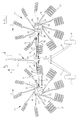
- the machine according to the invention comprises a support structure (1).
- This is in particular constituted by a beam (2) which is directed in the direction of advance (A).
- This beam (2) has at its front end a coupling device (3) for hooking it to a drive tractor which is not shown.
- At its rear end, it has two divergent supports (4 and 5), each having a carrier wheel (6 and 7) which rests on the ground.
- On each side of this beam (2) is articulated a telescopic arm (8 and 9) each carrying a raking wheel (10 and 11).
- Each telescopic arm (8, 9) could be provided with two raking wheels. In this case, the machine would have four in total and have a greater working width.
- Each of said arms (8 and 9) is made in two parts (12, 13 and 14, 15) in the form of tubes.
- Each first part (12, 14) is articulated on the support structure (1) by means of an axis (16, 17) which is substantially horizontal and directed in the direction of advance (A).
- Each second part (13, 15) can slide in the first part (12, 14) in order to ability to lengthen or shorten arms (8 and 9).
- These sliding parts (13 and 15) have stops (18 and 19) by means of which they bear against the first parts (12 and 14) when they are fully retracted.
- Other embodiments of the arms (8, 9) could also be used without departing from the scope of the invention.
- the two raking wheels (10, 11) are substantially identical.
- Each has a housing (20, 21) which is articulated at the end of the sliding part (13, 15) of each telescopic arm (8, 9) by means of an axis (22, 23) which is also substantially horizontal and directed in the direction of advancement (A).
- On either side of each axis (22, 23) are provided stops to limit, within a certain range, the pivoting of the raking wheels (10, 11).
- a support axis (24, 25) which is substantially vertical when the machine is in the working position.
- Each support pin (24, 25) carries at its end furthest from the casing (20, 21) a crosspiece (26) with two rollers (27 and 28) which are directed in the direction of advance (A). Between this crosspiece (26) and said casing (20, 21) of each raking wheel (10, 11) is provided a housing (29, 30) with arms (31) equipped with working tools (32) such as teeth.
- This housing (29, 30) is mounted on the support axis (24, 25) so that it can rotate around.
- the tool arms (31) are guided in bearings (33) integral with the housing (29, 30), so that they can pivot around their respective longitudinal geometric axes.
- a control cam which is fixed on the support axis (24, 25).
- Each tool arm (31) has at its end located in the housing (29, 30) a lever with a roller which is guided in said cam. Raking wheels with uncontrolled working tools could also equip the machine according to the invention.
- each raking wheel (10, 11) In the housing (20, 21) of each raking wheel (10, 11) are provided mechanical means for driving the housing (29, 30) in rotation about the support axis (24, 25). These means consist of a toothed crown which is integral with the upper part of the housing (29, 30) and a drive pinion which meshes with said crown. This pinion is linked to a shaft (34, 35) which extends out of the casing (20, 21) in the direction of the beam (2). On this shaft (34, 35) is mounted a transmission shaft (36, 37) with a universal joint near each of its ends. This transmission shaft (36, 37) is connected to a distribution casing (38) which is fixed under the beam (2) and which is connected, by other transmission shafts, to the PTO shaft of the tractor.
- each raking wheel (10, 11) is equipped with a hydraulic cylinder (39, 40) which allows it to be raised in a substantially vertical position for transport and lowered into a position substantially horizontal for work.
- Each cylinder (39, 40) is articulated with one of its ends on the structure (1) and with its other end on the first part (12, 14) of the corresponding arm (8, 9).
- Each telescopic arm (8, 9) has a spring device (41) located between its first part (12, 14) and its sliding part (13, 15).
- This spring device (41) is housed in the interior volume of these parts (12 to 15).
- the spring device (41) is constituted by a gas spring (42).
- the body (43) of this spring (42) is connected to the sliding part (13, 15) of the telescopic arm (8, 9) by means of an axis (44).
- Its rod (45) is connected to the first part (12, 14) of said telescopic arm, by means of an axis (46).
- the spring device (41) is consisting of a metal pressure spring (47). This spring is partially guided by the sliding part (13, 15) of the telescopic arm (8, 9). It is supported, on one side, against a plate (48) which is secured to said sliding part (13, 15) and, on the other side, against a plate (49) secured to the first part (12, 14) of the telescopic arm (8, 9).
- the part of the spring (47) which is located outside the sliding part (13, 15) can be guided by an internal rod, fixed on this plate (49).
- the spring device (41) is automatically compressed under the effect of the weight of said raking wheel (10, 11) and of the sliding part (13, 15) when these are moved in the transport position. Conversely, it automatically pushes the sliding part (13, 15) and the corresponding raking wheel (10, 11), so as to move them away from the carrying structure (1), when they are moved into the working position.
- Each telescopic arm (8, 9) has two stops (50 and 51), one of which is provided on its first part (12, 14) and the other on its sliding part (13, 15). These stops (50 and 51) limit the displacement towards the outside of the sliding part (13, 15).
- the position of the stop (51) is adjustable, which makes it possible to stop said sliding part in different working positions.
- the stop (50) is constituted by an eyelet which is integral with the first part (12, 14) of the telescopic arm (8, 9).
- the other stop (51) is constituted by a pin which is associated with the sliding part (13, 15).
- the latter comprises a rod (52) which is parallel to its longitudinal geometric axis. This rod slides in the eyelet which constitutes the stop (50) and has several orifices (53) for the pin constituting the stop (51). These orifices (53) are provided at regular intervals, on the part of the rod (52) which is directed towards the beam (2).
- the machine according to the invention is coupled to a tractor which moves it in the direction of the arrow (A) (see Figure 1).
- the two telescopic arms (8 and 9) are then lowered, so that the rollers (27 and 28) of the two raking wheels (10 and 11) rest on the ground.
- the housings (29 and 30) of these raking wheels are rotated in the direction of the arrows (G and H) from the tractor.
- each raking wheel (10, 11) are controlled by the cam which is housed in the housing (29, 30), so that their tools (32) rake the plants on the front part of their trajectory and deposit them in the form of a swath on the strip of land which is located between the two raking wheels (10 and 11).
- the working width of this machine can be increased or decreased by changing the length of the telescopic arms (8 and 9) and therefore the distance between the raking wheels (10 and 11). This allows the width to be increased, for example, when the plants are not dense. On the other hand, when they are very dense, the working width can be reduced in order to prevent the volume of the swath from being too great.
- the user determines the length of the telescopic arms (8 and 9) by means of the stops (50 and 51). For this, it suffices to move the stops (51) from one orifice (53) to the other.
- the orifice (53) which is closest to the beam (2) makes it possible to obtain the greatest length.
- the orifice (53) furthest from said beam (2) makes it possible to obtain the shortest length of the telescopic arm (8, 9).
- the holes (53) located between the two extreme holes allow to obtain intermediate widths.
- the positioning of the adjustable stops (51) takes place when the telescopic arms (8 and 9) are raised ( Figures 3 and 5). Then simply lower the telescopic arms (8 and 9) to the working position.
- the telescopic arms (8 and 9) can be locked by means of a locking device preventing any accidental return to the working position.
- the tool arms (31) may have removable external parts (54). The user thus has the possibility of dismantling those which are directed upwards, in order to obtain an additional reduction in the height of the machine.
Description
La présente invention concerne une machine agricole, notamment une andaineuse de végétaux couchés sur le sol, comportant une structure porteuse, au moins un bras télescopique qui est déplaçable d'une position de travail dans une position de transport et inversement, lequel bras est réalisé en au moins deux parties, une première qui est articulée sur la structure porteuse et une seconde qui peut coulisser par rapport à la première et, au moins un organe de travail tel qu'une roue râteleuse qui est articulée sur la partie coulissante du bras télescopique.The present invention relates to an agricultural machine, in particular a swather of plants lying on the ground, comprising a support structure, at least one telescopic arm which is movable from a working position into a transport position and vice versa, which arm is made of at least two parts, a first which is articulated on the support structure and a second which can slide relative to the first and, at least one working member such as a raking wheel which is articulated on the sliding part of the telescopic arm.
Le bras télescopique permet de modifier la position de la roue râteleuse par rapport à la structure porteuse. Ainsi, sur une andaineuse avec deux bras télescopiques portant chacun une roue râteleuse, il est possible de modifier la distance entre ces roues râteleuses. De cette manière, l'utilisateur peut modifier la largeur de travail de l'andaineuse en fonction des végétaux à andainer.The telescopic arm makes it possible to modify the position of the raking wheel relative to the supporting structure. Thus, on a swather with two telescopic arms each carrying a raking wheel, it is possible to modify the distance between these raking wheels. In this way, the user can modify the working width of the swather according to the plants to be swathed.
Sur une andaineuse connue de ce genre, la longueur des bras télescopiques est réglable au moyen de vérins hydrauliques. Cet agencement est tributaire du circuit hydraulique du tracteur. Il ne peut être actionné qu'au moyen d'un tracteur qui est équipé en conséquence. De plus, le prix des différents composants hydrauliques qui sont nécessaires sur la machine est relativement élevé.On a known swather of this kind, the length of the telescopic arms is adjustable by means of hydraulic cylinders. This arrangement is dependent on the hydraulic circuit of the tractor. It can only be operated by means of a tractor which is equipped accordingly. In addition, the price of the various hydraulic components that are required on the machine is relatively high.
Un autre inconvénient de l'agencement hydraulique consiste en ce que le raccourcissement des bras télescopiques, pour réduire la hauteur de la machine dans la position de transport, nécessite une commande expresse de la part de l'utilisateur. Cette opération peut cependant être omise. Dans ce cas, la machine est instable et elle peut se renverser, par exemple dans un virage. Les roues râteleuses peuvent aussi rester accrochées lorsque la machine passe sous un porche ou un pont, et subir d'importants dégâts.Another drawback of the hydraulic arrangement is that the shortening of the telescopic arms, in order to reduce the height of the machine in the transport position, requires an express order from the user. This operation can however be omitted. In this case, the machine is unstable and it can overturn, for example in a turn. The raking wheels can also remain hooked when the machine passes under a porch or a bridge, and to undergo important damage.
La présente invention a pour but de proposer une machine sur laquelle les différentes largeurs de travail peuvent être obtenues facilement et qui revient automatiquement dans la position la plus basse pour le transport.The object of the present invention is to propose a machine on which the different working widths can be obtained easily and which automatically returns to the lowest position for transport.
A cet effet, dans la machine agricole de l'invention chaque bras télescopique comporte un dispositif à ressort qui est situé entre sa première partie et sa partie coulissante, lequel dispositif se comprime sous l'effet du poids de l'organe de travail et de la partie coulissante correspondante lorsqu'ils sont déplacés en position de transport et, pousse ladite partie coulissante et l'organe de travail de manière à les éloigner de la structure porteuse lorsqu'ils sont déplacés en position de travail, ainsi que deux butées dont l'une est prévue sur la première partie et l'autre sur la partie coulissante de chaque bras télescopique, la position de l'une au moins de ces butées étant réglable en vue d'arrêter ladite partie coulissante dans différentes positions de travail.To this end, in the agricultural machine of the invention each telescopic arm comprises a spring device which is located between its first part and its sliding part, which device is compressed under the effect of the weight of the working member and of the corresponding sliding part when they are moved to the transport position and, pushes said sliding part and the working member so as to move them away from the support structure when they are moved to the working position, as well as two stops, the l 'One is provided on the first part and the other on the sliding part of each telescopic arm, the position of at least one of these stops being adjustable in order to stop said sliding part in different working positions.
Ce dispositif à ressort permet au bras télescopique correspondant de se raccourcir automatiquement lorsqu'il est déplacé en position de transport. Par ailleurs, il provoque automatiquement l'allongement dudit bras lorsqu' il est déplacé en position de travail. Différentes largeurs de travail peuvent être obtenues au moyen de la butée réglable.This spring device allows the corresponding telescopic arm to shorten automatically when it is moved to the transport position. Furthermore, it automatically causes said arm to lengthen when it is moved into the working position. Different working widths can be obtained by means of the adjustable stop.
Les moyens ainsi mis en oeuvre sont extrêmement simples. Ils fonctionnent sans composant hydraulique. Au transport, chaque bras télescopique revient automatiquement dans sa position la plus courte. La hauteur de la machine est ainsi réduite sans intervention expresse de la part de l'utilisateur, ce qui exclut toute omission.The means thus implemented are extremely simple. They operate without a hydraulic component. During transport, each telescopic arm automatically returns to its shortest position. The height of the machine is thus reduced without express intervention on the part of the user, which excludes any omission.
Le dispositif à ressort peut par exemple être constitué par un ressort de compression métallique ou bien un ressort à gaz. La force du ressort utilisé est de préférence comprise entre 50% et 95% du poids de la roue râteleuse et de la partie coulissante du bras porteur.The spring device can for example consist of a metal compression spring or a gas spring. The force of the spring used is preferably between 50% and 95% of the weight of the raking wheel and of the sliding part of the support arm.
D'autres caractéristiques et avantages de l'invention ressortiront des revendications et de la description ci-après de quelques exemples de réalisation non limitatifs de l'invention, avec référence aux dessins annexés dans lesquels :
- la figure 1 représente une vue de dessus d'une machine selon l'invention en position de travail,
- la figure 2 représente, à plus grande échelle et avec une coupe partielle, une vue de détail d'un premier exemple de réalisation d'un bras porteur d'un organe de travail, dans la position de travail,
- la figure 3 représente le bras porteur d'un organe de travail selon l'exemple de la figure 2, dans la position de transport,
- la figure 4 représente une vue similaire à celle de la figure 2, d'un second exemple de réalisation du bras porteur d'un organe de travail,
- la figure 5 représente le bras porteur selon l'exemple de la figure 4, dans la position de transport.
- FIG. 1 represents a top view of a machine according to the invention in the working position,
- FIG. 2 represents, on a larger scale and with a partial section, a detail view of a first embodiment of an arm carrying a working member, in the working position,
- FIG. 3 represents the carrying arm of a working member according to the example of FIG. 2, in the transport position,
- FIG. 4 represents a view similar to that of FIG. 2, of a second embodiment of the support arm of a working member,
- 5 shows the support arm according to the example of Figure 4, in the transport position.
Comme cela ressort notamment de la figure 1, la machine selon l'invention comporte une structure porteuse (1). Celle-ci est notamment constituée par une poutre (2) qui est dirigée dans la direction d'avancement (A). Cette poutre (2) possède à son extrémité avant un dispositif d'accouplement (3) pour l'accrocher à un tracteur d'entraînement qui n'est pas représenté. A son extrémité arrière, elle possède deux supports (4 et 5) divergents, ayant chacun une roue porteuse (6 et 7) qui repose sur le sol. Sur chaque côté de cette poutre (2) est articulé un bras télescopique (8 et 9) portant chacun une roue râteleuse (10 et 11). Chaque bras télescopique (8, 9) pourrait être muni de deux roues râteleuses. Dans ce cas, la machine en comporterait quatre au total et aurait une largeur de travail plus importante. Chacun desdits bras (8 et 9) est réalisé en deux parties (12, 13 et 14, 15) en forme de tubes. Chaque première partie (12, 14) est articulée sur la structure porteuse (1) au moyen d'un axe (16, 17) qui est sensiblement horizontal et dirigé dans la direction d'avancement (A). Chaque deuxième partie (13, 15) peut coulisser dans la première partie (12, 14) en vue de pouvoir allonger ou raccourcir les bras (8 et 9). Ces parties coulissantes (13 et 15) comportent des arrêts (18 et 19) au moyen desquels elles s'appuient contre les premières parties (12 et 14) lorsqu'elles sont totalement rétractées. D'autres modes de réalisation des bras (8, 9) pourraient également être utilisés sans sortir pour autant du cadre de l'invention.As is apparent in particular from FIG. 1, the machine according to the invention comprises a support structure (1). This is in particular constituted by a beam (2) which is directed in the direction of advance (A). This beam (2) has at its front end a coupling device (3) for hooking it to a drive tractor which is not shown. At its rear end, it has two divergent supports (4 and 5), each having a carrier wheel (6 and 7) which rests on the ground. On each side of this beam (2) is articulated a telescopic arm (8 and 9) each carrying a raking wheel (10 and 11). Each telescopic arm (8, 9) could be provided with two raking wheels. In this case, the machine would have four in total and have a greater working width. Each of said arms (8 and 9) is made in two parts (12, 13 and 14, 15) in the form of tubes. Each first part (12, 14) is articulated on the support structure (1) by means of an axis (16, 17) which is substantially horizontal and directed in the direction of advance (A). Each second part (13, 15) can slide in the first part (12, 14) in order to ability to lengthen or shorten arms (8 and 9). These sliding parts (13 and 15) have stops (18 and 19) by means of which they bear against the first parts (12 and 14) when they are fully retracted. Other embodiments of the arms (8, 9) could also be used without departing from the scope of the invention.
Les deux roues râteleuses (10, 11) sont sensiblement identiques. Chacune comporte un carter (20, 21) qui est articulé à l'extrémité de la partie coulissante (13, 15) de chaque bras télescopique (8, 9) au moyen d'un axe (22, 23) qui est également sensiblement horizontal et dirigé dans la direction d'avancement (A). De part et d'autre de chaque axe (22, 23) sont prévues des butées pour limiter, dans une certaine fourchette, les pivotements des roues râteleuses (10, 11). Dans chacun de ces carters (20, 21) est fixé un axe support (24, 25) qui est sensiblement vertical lorsque la machine est dans la position de travail. Chaque axe support (24, 25) porte à son extrémité la plus éloignée du carter (20, 21) une traverse (26) avec deux roulettes (27 et 28) qui sont dirigées dans la direction d'avancement (A). Entre cette traverse (26) et ledit carter (20, 21) de chaque roue râteleuse (10, 11) est prévu un boîtier (29, 30) avec des bras (31) équipés d'outils de travail (32) tels que des dents. Ce boîtier (29, 30) est monté sur l'axe support (24, 25) de manière à pouvoir tourner autour. Les bras porte-outils (31) sont guidés dans des paliers (33) solidaires du boîtier (29, 30), de sorte qu'ils puissent pivoter autour de leurs axes géométriques longitudinaux respectifs. A l'intérieur de ce boîtier (29, 30) est prévue, d'une manière connue, une came de commande qui est fixée sur l'axe support (24, 25). Chaque bras porte-outils (31) comporte à son extrémité située dans le boîtier (29, 30) un levier avec un galet qui est guidé dans ladite came. Des roues râteleuses avec des outils de travail non commandés pourraient également équiper la machine selon l'invention.The two raking wheels (10, 11) are substantially identical. Each has a housing (20, 21) which is articulated at the end of the sliding part (13, 15) of each telescopic arm (8, 9) by means of an axis (22, 23) which is also substantially horizontal and directed in the direction of advancement (A). On either side of each axis (22, 23) are provided stops to limit, within a certain range, the pivoting of the raking wheels (10, 11). In each of these housings (20, 21) is fixed a support axis (24, 25) which is substantially vertical when the machine is in the working position. Each support pin (24, 25) carries at its end furthest from the casing (20, 21) a crosspiece (26) with two rollers (27 and 28) which are directed in the direction of advance (A). Between this crosspiece (26) and said casing (20, 21) of each raking wheel (10, 11) is provided a housing (29, 30) with arms (31) equipped with working tools (32) such as teeth. This housing (29, 30) is mounted on the support axis (24, 25) so that it can rotate around. The tool arms (31) are guided in bearings (33) integral with the housing (29, 30), so that they can pivot around their respective longitudinal geometric axes. Inside this housing (29, 30) is provided, in a known manner, a control cam which is fixed on the support axis (24, 25). Each tool arm (31) has at its end located in the housing (29, 30) a lever with a roller which is guided in said cam. Raking wheels with uncontrolled working tools could also equip the machine according to the invention.
Dans le carter (20, 21) de chaque roue râteleuse (10, 11) sont prévus des moyens mécaniques pour entraîner le boîtier (29, 30) en rotation autour de l'axe support (24, 25). Ces moyens sont constitués par une couronne dentée qui est solidaire de la partie supérieure du boîtier (29, 30) et un pignon d'entraînement qui engrène avec ladite couronne. Ce pignon est lié à un arbre (34, 35) qui s'étend hors du carter (20, 21) en direction de la poutre (2). Sur cet arbre (34, 35) est monté un arbre de transmission (36, 37) avec un joint de cardan près de chacune de ses extrémités. Cet arbre de transmission (36, 37) est relié à un carter de distribution (38) qui est fixé sous la poutre (2) et qui est relié, par d'autres arbres de transmission, à l'arbre de prise de force du tracteur.In the housing (20, 21) of each raking wheel (10, 11) are provided mechanical means for driving the housing (29, 30) in rotation about the support axis (24, 25). These means consist of a toothed crown which is integral with the upper part of the housing (29, 30) and a drive pinion which meshes with said crown. This pinion is linked to a shaft (34, 35) which extends out of the casing (20, 21) in the direction of the beam (2). On this shaft (34, 35) is mounted a transmission shaft (36, 37) with a universal joint near each of its ends. This transmission shaft (36, 37) is connected to a distribution casing (38) which is fixed under the beam (2) and which is connected, by other transmission shafts, to the PTO shaft of the tractor.
Le bras télescopique (8, 9) de chaque roue râteleuse (10, 11) est équipé d'un vérin hydraulique (39, 40) qui permet de le relever dans une position sensiblement verticale pour le transport et de l'abaisser dans une position sensiblement horizontale pour le travail. Chaque vérin (39, 40) est articulé avec une de ses extrémités sur la structure (1) et avec son autre extrémité sur la première partie (12, 14) du bras (8, 9) correspondant.The telescopic arm (8, 9) of each raking wheel (10, 11) is equipped with a hydraulic cylinder (39, 40) which allows it to be raised in a substantially vertical position for transport and lowered into a position substantially horizontal for work. Each cylinder (39, 40) is articulated with one of its ends on the structure (1) and with its other end on the first part (12, 14) of the corresponding arm (8, 9).
Chaque bras télescopique (8, 9) comporte un dispositif à ressort (41) situé entre sa première partie (12, 14) et sa partie coulissante (13, 15). Ce dispositif à ressort (41) est logé dans le volume intérieur de ces parties (12 à 15). Dans l'exemple de réalisation qui est représenté sur les figures 2 et 3, le dispositif à ressort (41) est constitué par un ressort à gaz (42). Le corps (43) de ce ressort (42) est relié à la partie coulissante (13, 15) du bras télescopique (8, 9) au moyen d'un axe (44). Sa tige (45) est reliée à la première partie (12, 14) dudit bras télescopique, au moyen d'un axe (46).Each telescopic arm (8, 9) has a spring device (41) located between its first part (12, 14) and its sliding part (13, 15). This spring device (41) is housed in the interior volume of these parts (12 to 15). In the embodiment which is shown in Figures 2 and 3, the spring device (41) is constituted by a gas spring (42). The body (43) of this spring (42) is connected to the sliding part (13, 15) of the telescopic arm (8, 9) by means of an axis (44). Its rod (45) is connected to the first part (12, 14) of said telescopic arm, by means of an axis (46).
Selon l'exemple de réalisation qui est représenté sur les figures 4 et 5, le dispositif à ressort (41) est constitué par un ressort de pression métallique (47). Ce ressort est partiellement guidé par la partie coulissante (13, 15) du bras télescopique (8, 9). Il s'appuie, d'un côté, contre une plaque (48) qui est solidaire de ladite partie coulissante (13, 15) et, de l'autre côté, contre une plaque (49) solidaire de la première partie (12, 14) du bras télescopique (8, 9).According to the exemplary embodiment which is represented in FIGS. 4 and 5, the spring device (41) is consisting of a metal pressure spring (47). This spring is partially guided by the sliding part (13, 15) of the telescopic arm (8, 9). It is supported, on one side, against a plate (48) which is secured to said sliding part (13, 15) and, on the other side, against a plate (49) secured to the first part (12, 14) of the telescopic arm (8, 9).
La partie du ressort (47) qui se situe en-dehors de la partie coulissante (13, 15) peut être guidée par une tige intérieure, fixée sur cette plaque (49).The part of the spring (47) which is located outside the sliding part (13, 15) can be guided by an internal rod, fixed on this plate (49).
La force du dispositif à ressort (41), c'est-à-dire aussi bien du ressort à gaz (42) que du ressort de pression (47), est inférieure au poids de la roue râteleuse (10, 11) et de la partie coulissante (13, 15) correspondante du bras télescopique (8, 9). Ladite force est avantageusement comprise entre 50% et 95% dudit poids. Ainsi, le dispositif à ressort (41) se comprime automatiquement sous l'effet du poids de ladite roue râteleuse (10, 11) et de la partie coulissante (13, 15) lorsque celles-ci sont déplacées en position de transport. Inversement, il pousse automatiquement la partie coulissante (13, 15) et la roue râteleuse (10, 11) correspondante, de manière à les éloigner de la structure porteuse (1), lorsqu'elles sont déplacées en position de travail.The force of the spring device (41), i.e. both the gas spring (42) and the pressure spring (47), is less than the weight of the raking wheel (10, 11) and the corresponding sliding part (13, 15) of the telescopic arm (8, 9). Said force is advantageously between 50% and 95% of said weight. Thus, the spring device (41) is automatically compressed under the effect of the weight of said raking wheel (10, 11) and of the sliding part (13, 15) when these are moved in the transport position. Conversely, it automatically pushes the sliding part (13, 15) and the corresponding raking wheel (10, 11), so as to move them away from the carrying structure (1), when they are moved into the working position.
Chaque bras télescopique (8, 9) comporte deux butées (50 et 51) dont l'une est prévue sur sa première partie (12, 14) et l'autre sur sa partie coulissante (13, 15). Ces butées (50 et 51) limitent le déplacement vers l'extérieur de la partie coulissante (13, 15). La position de la butée (51) est réglable, ce qui permet d'arrêter ladite partie coulissante dans différentes positions de travail.Each telescopic arm (8, 9) has two stops (50 and 51), one of which is provided on its first part (12, 14) and the other on its sliding part (13, 15). These stops (50 and 51) limit the displacement towards the outside of the sliding part (13, 15). The position of the stop (51) is adjustable, which makes it possible to stop said sliding part in different working positions.
La butée (50) est constituée par un oeillet qui est solidaire de la première partie (12, 14) du bras télescopique (8, 9). L'autre butée (51) est constituée par une broche qui est associée à la partie coulissante (13, 15). Cette dernière comporte une tige (52) qui est parallèle à son axe géométrique longitudinal. Cette tige coulisse dans l'oeillet qui constitue la butée (50) et comporte plusieurs orifices (53) pour la broche constituant la butée (51). Ces orifices (53) sont prévus à des intervalles réguliers, sur la partie de la tige (52) qui est dirigée vers la poutre (2).The stop (50) is constituted by an eyelet which is integral with the first part (12, 14) of the telescopic arm (8, 9). The other stop (51) is constituted by a pin which is associated with the sliding part (13, 15). The latter comprises a rod (52) which is parallel to its longitudinal geometric axis. This rod slides in the eyelet which constitutes the stop (50) and has several orifices (53) for the pin constituting the stop (51). These orifices (53) are provided at regular intervals, on the part of the rod (52) which is directed towards the beam (2).
Durant le travail, la machine selon l'invention est attelée à un tracteur qui la déplace dans le sens de la flèche (A) (voir figure 1). Les deux bras télescopiques (8 et 9) sont alors abaissés, de sorte que les roulettes (27 et 28) des deux roues râteleuses (10 et 11) reposent sur le sol. Les boîtiers (29 et 30) de ces roues râteleuses sont entraînés en rotation dans le sens des flèches (G et H) à partir du tracteur. Durant cette rotation, les bras porte-outils (31) de chaque roue râteleuse (10, 11) sont commandés par la came qui est logée dans le boîtier (29, 30), de telle sorte que leurs outils (32) râtellent les végétaux sur la partie avant de leur trajectoire et les déposent sous la forme d'un andain sur la bande de terrain qui est située entre les deux roues râteleuses (10 et 11).During work, the machine according to the invention is coupled to a tractor which moves it in the direction of the arrow (A) (see Figure 1). The two telescopic arms (8 and 9) are then lowered, so that the rollers (27 and 28) of the two raking wheels (10 and 11) rest on the ground. The housings (29 and 30) of these raking wheels are rotated in the direction of the arrows (G and H) from the tractor. During this rotation, the tool arms (31) of each raking wheel (10, 11) are controlled by the cam which is housed in the housing (29, 30), so that their tools (32) rake the plants on the front part of their trajectory and deposit them in the form of a swath on the strip of land which is located between the two raking wheels (10 and 11).
La largeur de travail de cette machine peut être augmentée ou diminuée en modifiant la longueur des bras télescopiques (8 et 9) et par conséquent la distance entre les roues râteleuses (10 et 11). Ceci permet d'augmenter la largeur, par exemple, lorsque les végétaux ne sont pas denses. Par contre, lorsqu'ils sont très denses, la largeur de travail peut être réduite afin d'éviter que le volume de l'andain ne soit trop important.The working width of this machine can be increased or decreased by changing the length of the telescopic arms (8 and 9) and therefore the distance between the raking wheels (10 and 11). This allows the width to be increased, for example, when the plants are not dense. On the other hand, when they are very dense, the working width can be reduced in order to prevent the volume of the swath from being too great.
Sur cette machine, l'utilisateur détermine la longueur des bras télescopiques (8 et 9) au moyen des butées (50 et 51). Pour cela, il lui suffit de déplacer les butées (51) d'un orifice (53) à l'autre. Sur chaque bras télescopique (8 ou 9), l'orifice (53) qui est le plus proche de la poutre (2) permet d'obtenir la plus importante longueur. Inversement, l'orifice (53) le plus éloigné de ladite poutre (2) permet d'obtenir la plus faible longueur du bras télescopique (8, 9). Les orifices (53) situés entre les deux orifices extrêmes permettent d'obtenir des largeurs intermédiaires. Le positionnement des butées réglables (51) s'effectue lorsque les bras télescopiques (8 et 9) sont relevés (figures 3 et 5). Ensuite, il suffit d'abaisser les bras télescopiques (8 et 9) dans la position de travail. Dès qu'ils approchent de la position horizontale, les dispositifs à ressort (41) poussent les parties coulissantes (13 et 15) avec les roues râteleuses (10 et 11) vers l'extérieur jusqu'à ce que les butées réglables (51) rencontrent les butées fixes (50). La machine est alors dans la position de travail souhaitée (figures 2 et 4).On this machine, the user determines the length of the telescopic arms (8 and 9) by means of the stops (50 and 51). For this, it suffices to move the stops (51) from one orifice (53) to the other. On each telescopic arm (8 or 9), the orifice (53) which is closest to the beam (2) makes it possible to obtain the greatest length. Conversely, the orifice (53) furthest from said beam (2) makes it possible to obtain the shortest length of the telescopic arm (8, 9). The holes (53) located between the two extreme holes allow to obtain intermediate widths. The positioning of the adjustable stops (51) takes place when the telescopic arms (8 and 9) are raised (Figures 3 and 5). Then simply lower the telescopic arms (8 and 9) to the working position. As soon as they approach the horizontal position, the spring devices (41) push the sliding parts (13 and 15) with the raking wheels (10 and 11) outwards until the adjustable stops (51) meet the fixed stops (50). The machine is then in the desired working position (Figures 2 and 4).
Par ailleurs, lorsque les bras télescopiques (8 et 9) sont relevés en position de transport au moyen des vérins hydrauliques (39 et 40), leurs roues râteleuses (10 et 11) compriment les dispositifs à ressort (41). Lesdites roues râteleuses reviennent alors automatiquement, avec les parties coulissantes (13 et 15), dans la position la plus basse possible. Dans cette position, les bras télescopiques (8 et 9) sont entièrement rétractés (figures 3 et 5). La hauteur de la machine est ainsi automatiquement réduite.Furthermore, when the telescopic arms (8 and 9) are raised to the transport position by means of the hydraulic cylinders (39 and 40), their raking wheels (10 and 11) compress the spring devices (41). Said raking wheels then return automatically, with the sliding parts (13 and 15), to the lowest possible position. In this position, the telescopic arms (8 and 9) are fully retracted (Figures 3 and 5). The height of the machine is thus automatically reduced.
Dans cette position de transport, les bras télescopiques (8 et 9) peuvent être bloqués au moyen d'un dispositif de verrouillage évitant tout retour accidentel en position de travail. Les bras porte-outils (31) peuvent avoir des parties extérieures (54) démontables. L'utilisateur a ainsi la possibilité de démonter celles qui sont dirigées vers le haut, afin d'obtenir une réduction supplémentaire de la hauteur de la machine.In this transport position, the telescopic arms (8 and 9) can be locked by means of a locking device preventing any accidental return to the working position. The tool arms (31) may have removable external parts (54). The user thus has the possibility of dismantling those which are directed upwards, in order to obtain an additional reduction in the height of the machine.
Il est bien évident que l'invention n'est pas limitée aux modes de réalisation décrits ci-dessus et représentés sur les dessins annexés. Des modifications restent possibles, notamment en ce qui concerne la constitution ou le nombre des divers éléments ou par substitution d'équivalents techniques, sans pour autant sortir du domaine de protection tel que défini dans les revendications.It is obvious that the invention is not limited to the embodiments described above and shown in the accompanying drawings. Modifications remain possible, in particular as regards the constitution or the number of the various elements or by substitution of technical equivalents, without however departing from the field of protection as defined in the claims.
Claims (6)
- Agricultural machine, especially a windrower for plants lying on the ground, comprising a carrying structure, at least one telescopic arm which is displaceable from a work position in a transport position and vice versa, the said arm being achieved in at least two parts, a first one which is articulated on the carrying structure and a second one which can slide with regard to the first part and, at least one working tool like a raking wheel, which is articulated on the sliding part of the telescopic arm, characterised in that each telescopic arm (8, 9) comprises a device with a spring (51) located between its first part (12, 14) and its sliding part (13, 15), which device (41) is compressed under the action of the weight of the working tool (10, 11) and of the corresponding sliding part (13, 15), when these are displaced in the transport position and, push the said sliding part (13, 15) and the working tool (10, 11) so as to move them away from the carrying structure (1) when they are displaced in the work position, as well as two stops (50 and 51) one of which is foreseen on the first part (12, 14) and the other on the sliding part (13, 15) of each telescopic arm (8, 9), the position of one at least of these stops being adjustable in order to stop the said sliding part (13, 15) in different work positions.
- Machine according to claim 1, characterised in that the device with a spring (41) is made up of a metal compression-spring (47) located between the first part (12, 14) and the sliding part (13, 15) of each telescopic arm (8, 9).
- Machine according to claim 1, characterised in that the device with a spring (41) is made up of a gas spring (42) located between the first part (12, 14) and the sliding part (13, 15) of each telescopic arm (8, 9).
- Machine according to claim 1, 2 or 3, characterised in that the strength of each device with a spring (41) is smaller than the weight of the corresponding raking wheel (10, 11) and of the sliding part (13, 15) of the telescopic arms (8, 9).
- Machine according to claim 1, characterised in that one of the stops (50) is made up of an eyelet which is integral with the first part (12, 14) of the telescopic arm (8, 9).
- Machine according to claim 5, characterised in that the sliding part (13, 15) of the telescopic arm (8, 9) comprises a rod (52) which is parallel to its longitudinal axis, which rod (42) slides in the eyelet constituting one of the stops (50) and comprises several positioning holes (53) for a spindle constituting the other stop (51).
Applications Claiming Priority (2)
| Application Number | Priority Date | Filing Date | Title |
|---|---|---|---|
| FR9106906A FR2677213B1 (en) | 1991-06-05 | 1991-06-05 | AGRICULTURAL MACHINE, ESPECIALLY A PLANT SWATHER. |
| FR9106906 | 1991-06-05 |
Publications (2)
| Publication Number | Publication Date |
|---|---|
| EP0517632A1 EP0517632A1 (en) | 1992-12-09 |
| EP0517632B1 true EP0517632B1 (en) | 1995-06-07 |
Family
ID=9413573
Family Applications (1)
| Application Number | Title | Priority Date | Filing Date |
|---|---|---|---|
| EP92440066A Expired - Lifetime EP0517632B1 (en) | 1991-06-05 | 1992-06-03 | Agricultural machine, especially a plant windrower |
Country Status (3)
| Country | Link |
|---|---|
| EP (1) | EP0517632B1 (en) |
| DE (1) | DE69202821T2 (en) |
| FR (1) | FR2677213B1 (en) |
Cited By (1)
| Publication number | Priority date | Publication date | Assignee | Title |
|---|---|---|---|---|
| PL442429A1 (en) * | 2022-10-01 | 2024-04-02 | Samasz Spółka Z Ograniczoną Odpowiedzialnością | Machine for harvesting roughage and straw |
Families Citing this family (14)
| Publication number | Priority date | Publication date | Assignee | Title |
|---|---|---|---|---|
| DE9305014U1 (en) * | 1993-04-06 | 1993-06-17 | H. Niemeyer Soehne Gmbh & Co Kg, 4446 Hoerstel, De | |
| AT404535B (en) * | 1993-08-16 | 1998-12-28 | Poettinger Ohg Alois | SUPPORTING FRAME FOR A DRIVABLE AGRICULTURAL MACHINING MACHINE |
| CA2182749A1 (en) * | 1996-08-06 | 1998-02-07 | Anthony Richard Vonesch | Lifting mechanism for rotary hay raking machine |
| FR2828988B1 (en) | 2001-09-06 | 2004-07-30 | Kuhn Sa | FENAISON MACHINE HAVING ROTORS LINKED TO CARRIER ARMS MADE IN TWO TELESCOPIC PARTS |
| DE10258661A1 (en) * | 2002-12-13 | 2004-07-22 | Claas Saulgau Gmbh | swathers |
| FR2882622B1 (en) * | 2005-03-04 | 2013-03-08 | Gyrland Ind Sas | ANDAINEUSE WITH TELESCOPIC ROTOR HOLDER ARMS |
| DE102005053060B4 (en) * | 2005-11-04 | 2015-11-12 | LTH Landtechnik Hohenmölsen GmbH | Hay-making machine |
| FR2945403B1 (en) * | 2009-05-14 | 2014-10-17 | Kuhn Sa | FASHION MACHINE, IN PARTICULAR AN ANDAINEUSE OF PLANTS. |
| DE102012009073B4 (en) * | 2012-05-09 | 2016-01-21 | Maschinenfabrik Bernard Krone Gmbh | Hay-making machine |
| JP6251138B2 (en) * | 2014-07-29 | 2017-12-20 | 株式会社タカキタ | Foldable twin rake |
| NL2014796B1 (en) * | 2015-05-12 | 2017-01-27 | Forage Innovations Bv | Agricultural machine. |
| EP3254549B1 (en) | 2016-06-08 | 2019-03-20 | Kverneland Group Kerteminde AS | Agricultural machine |
| GB201915531D0 (en) * | 2019-10-25 | 2019-12-11 | Agco Int Gmbh | Improved agricultural implement |
| DE102022112568A1 (en) * | 2022-05-19 | 2023-11-23 | Maschinenfabrik Bernard Krone GmbH & Co. KG | Agricultural implement for attachment or attachment to a towing vehicle and method for setting up on-road operation of an agricultural implement |
Family Cites Families (4)
| Publication number | Priority date | Publication date | Assignee | Title |
|---|---|---|---|---|
| CH654977A5 (en) * | 1985-05-02 | 1986-03-27 | Reisch Ag | Windrower with two rotors |
| DE3716927C3 (en) * | 1987-05-20 | 1998-12-10 | Greenland Gmbh & Co Kg | Haymaking machine |
| DE3903764A1 (en) * | 1989-02-09 | 1990-08-16 | Claas Saulgau Gmbh | CYLINDER HEAT MACHINES |
| FR2664127B1 (en) * | 1990-07-05 | 1994-05-27 | Kuhn Sa | AGRICULTURAL MACHINE, ESPECIALLY A PLANT SWATHER, WITH ADJUSTABLE WORKING WIDTH. |
-
1991
- 1991-06-05 FR FR9106906A patent/FR2677213B1/en not_active Expired - Fee Related
-
1992
- 1992-06-03 EP EP92440066A patent/EP0517632B1/en not_active Expired - Lifetime
- 1992-06-03 DE DE69202821T patent/DE69202821T2/en not_active Expired - Fee Related
Cited By (1)
| Publication number | Priority date | Publication date | Assignee | Title |
|---|---|---|---|---|
| PL442429A1 (en) * | 2022-10-01 | 2024-04-02 | Samasz Spółka Z Ograniczoną Odpowiedzialnością | Machine for harvesting roughage and straw |
Also Published As
| Publication number | Publication date |
|---|---|
| DE69202821D1 (en) | 1995-07-13 |
| DE69202821T2 (en) | 1996-02-08 |
| EP0517632A1 (en) | 1992-12-09 |
| FR2677213A1 (en) | 1992-12-11 |
| FR2677213B1 (en) | 1993-09-24 |
Similar Documents
| Publication | Publication Date | Title |
|---|---|---|
| EP0517632B1 (en) | Agricultural machine, especially a plant windrower | |
| EP0526365B1 (en) | Haymaking machine, particularly a crop windrower | |
| EP0203023B2 (en) | Haymaking machines with several raking wheels | |
| CA2833103A1 (en) | Agricultural machine with improved folding device | |
| EP0385899A1 (en) | Hay-making machine having a plurality of rotors | |
| EP0465393B1 (en) | An agricultural machine, especially a crop windrower, with an adjustable working width | |
| EP0514302B1 (en) | Improved crop windrower | |
| EP0310532B2 (en) | Hay-making machine having an improved protective device | |
| EP1142468A1 (en) | Haymaking machine | |
| EP0692185A1 (en) | Haymaking machine, especially a swather with controled fork-carrying arms | |
| EP1926363B1 (en) | Haying machine with foldable lateral structures | |
| EP0797913A1 (en) | Haymaking machine | |
| FR2707450A1 (en) | Hay-making machine with tedding or windrowing rotors equipped with wheels for resting on the ground | |
| FR2759245A1 (en) | FENAISON MACHINE WITH A GROUND SUPPORT DEVICE INCLUDING AT LEAST A BALANCER WITH TWO CARRIER WHEELS AND A MEANS FOR MOVING THIS BALANCER FOR TRANSPORT | |
| EP0558430A1 (en) | Hay windrower with a mechanism for stopping the driving of the rotor | |
| EP0914766B1 (en) | Haymaking machine | |
| EP0733302B1 (en) | Haymaking machine | |
| EP0654209B1 (en) | Haymaking machine | |
| EP1942719B1 (en) | Haying machine | |
| EP0593378B1 (en) | Haymaking machine for the windrowing of forage | |
| FR2700916A1 (en) | Haymaking machine with adjustable lateral guard | |
| EP3973756A1 (en) | Trailed agricultural machine for harvesting with an adjustable axle | |
| EP0532443A1 (en) | Haymaking machine with adjustable wheels | |
| FR2699044A1 (en) | Haymaking machine with displaceable wheels - comprises wheel arm carriers connected to pivoting axle with hydraulic actuator operated rack and pinion | |
| EP1029439A1 (en) | Haymaking machine |
Legal Events
| Date | Code | Title | Description |
|---|---|---|---|
| PUAI | Public reference made under article 153(3) epc to a published international application that has entered the european phase |
Free format text: ORIGINAL CODE: 0009012 |
|
| AK | Designated contracting states |
Kind code of ref document: A1 Designated state(s): DE FR IT NL |
|
| 17P | Request for examination filed |
Effective date: 19930525 |
|
| 17Q | First examination report despatched |
Effective date: 19940812 |
|
| GRAA | (expected) grant |
Free format text: ORIGINAL CODE: 0009210 |
|
| AK | Designated contracting states |
Kind code of ref document: B1 Designated state(s): DE FR IT NL |
|
| ITF | It: translation for a ep patent filed |
Owner name: BARZANO' E ZANARDO MILANO S.P.A. |
|
| REF | Corresponds to: |
Ref document number: 69202821 Country of ref document: DE Date of ref document: 19950713 |
|
| PLBE | No opposition filed within time limit |
Free format text: ORIGINAL CODE: 0009261 |
|
| STAA | Information on the status of an ep patent application or granted ep patent |
Free format text: STATUS: NO OPPOSITION FILED WITHIN TIME LIMIT |
|
| 26N | No opposition filed | ||
| PGFP | Annual fee paid to national office [announced via postgrant information from national office to epo] |
Ref country code: NL Payment date: 20070528 Year of fee payment: 16 |
|
| PGFP | Annual fee paid to national office [announced via postgrant information from national office to epo] |
Ref country code: DE Payment date: 20070530 Year of fee payment: 16 |
|
| PGFP | Annual fee paid to national office [announced via postgrant information from national office to epo] |
Ref country code: IT Payment date: 20070620 Year of fee payment: 16 |
|
| PGFP | Annual fee paid to national office [announced via postgrant information from national office to epo] |
Ref country code: FR Payment date: 20070627 Year of fee payment: 16 |
|
| NLV4 | Nl: lapsed or anulled due to non-payment of the annual fee |
Effective date: 20090101 |
|
| REG | Reference to a national code |
Ref country code: FR Ref legal event code: ST Effective date: 20090228 |
|
| PG25 | Lapsed in a contracting state [announced via postgrant information from national office to epo] |
Ref country code: DE Free format text: LAPSE BECAUSE OF NON-PAYMENT OF DUE FEES Effective date: 20090101 |
|
| PG25 | Lapsed in a contracting state [announced via postgrant information from national office to epo] |
Ref country code: NL Free format text: LAPSE BECAUSE OF NON-PAYMENT OF DUE FEES Effective date: 20090101 |
|
| PG25 | Lapsed in a contracting state [announced via postgrant information from national office to epo] |
Ref country code: IT Free format text: LAPSE BECAUSE OF NON-PAYMENT OF DUE FEES Effective date: 20080603 Ref country code: FR Free format text: LAPSE BECAUSE OF NON-PAYMENT OF DUE FEES Effective date: 20080630 |