EP0517334A1 - Swivel-sliding door system for a vehicle - Google Patents
Swivel-sliding door system for a vehicle Download PDFInfo
- Publication number
- EP0517334A1 EP0517334A1 EP92201601A EP92201601A EP0517334A1 EP 0517334 A1 EP0517334 A1 EP 0517334A1 EP 92201601 A EP92201601 A EP 92201601A EP 92201601 A EP92201601 A EP 92201601A EP 0517334 A1 EP0517334 A1 EP 0517334A1
- Authority
- EP
- European Patent Office
- Prior art keywords
- swivel
- sliding door
- rail
- door system
- drive
- Prior art date
- Legal status (The legal status is an assumption and is not a legal conclusion. Google has not performed a legal analysis and makes no representation as to the accuracy of the status listed.)
- Granted
Links
- 230000008878 coupling Effects 0.000 claims abstract description 15
- 238000010168 coupling process Methods 0.000 claims abstract description 15
- 238000005859 coupling reaction Methods 0.000 claims abstract description 15
- 230000005540 biological transmission Effects 0.000 claims description 8
- 239000000969 carrier Substances 0.000 claims 1
- 239000000725 suspension Substances 0.000 description 4
- 238000012986 modification Methods 0.000 description 2
- 230000004048 modification Effects 0.000 description 2
- 238000010276 construction Methods 0.000 description 1
- 238000006073 displacement reaction Methods 0.000 description 1
- 238000012423 maintenance Methods 0.000 description 1
- 238000004519 manufacturing process Methods 0.000 description 1
Images


Classifications
-
- B—PERFORMING OPERATIONS; TRANSPORTING
- B61—RAILWAYS
- B61D—BODY DETAILS OR KINDS OF RAILWAY VEHICLES
- B61D19/00—Door arrangements specially adapted for rail vehicles
- B61D19/003—Door arrangements specially adapted for rail vehicles characterised by the movements of the door
- B61D19/009—Door arrangements specially adapted for rail vehicles characterised by the movements of the door both sliding and plugging, (e.g. for refrigerator cars)
-
- B—PERFORMING OPERATIONS; TRANSPORTING
- B60—VEHICLES IN GENERAL
- B60J—WINDOWS, WINDSCREENS, NON-FIXED ROOFS, DOORS, OR SIMILAR DEVICES FOR VEHICLES; REMOVABLE EXTERNAL PROTECTIVE COVERINGS SPECIALLY ADAPTED FOR VEHICLES
- B60J5/00—Doors
- B60J5/04—Doors arranged at the vehicle sides
- B60J5/06—Doors arranged at the vehicle sides slidable; foldable
- B60J5/062—Doors arranged at the vehicle sides slidable; foldable for utility vehicles or public transport
-
- E—FIXED CONSTRUCTIONS
- E05—LOCKS; KEYS; WINDOW OR DOOR FITTINGS; SAFES
- E05D—HINGES OR SUSPENSION DEVICES FOR DOORS, WINDOWS OR WINGS
- E05D15/00—Suspension arrangements for wings
- E05D15/06—Suspension arrangements for wings for wings sliding horizontally more or less in their own plane
- E05D15/10—Suspension arrangements for wings for wings sliding horizontally more or less in their own plane movable out of one plane into a second parallel plane
- E05D15/1042—Suspension arrangements for wings for wings sliding horizontally more or less in their own plane movable out of one plane into a second parallel plane with transversely moving carriage
- E05D15/1044—Suspension arrangements for wings for wings sliding horizontally more or less in their own plane movable out of one plane into a second parallel plane with transversely moving carriage specially adapted for use in railway-cars or mass transit vehicles
-
- E—FIXED CONSTRUCTIONS
- E05—LOCKS; KEYS; WINDOW OR DOOR FITTINGS; SAFES
- E05D—HINGES OR SUSPENSION DEVICES FOR DOORS, WINDOWS OR WINGS
- E05D15/00—Suspension arrangements for wings
- E05D15/06—Suspension arrangements for wings for wings sliding horizontally more or less in their own plane
- E05D15/10—Suspension arrangements for wings for wings sliding horizontally more or less in their own plane movable out of one plane into a second parallel plane
- E05D15/1065—Suspension arrangements for wings for wings sliding horizontally more or less in their own plane movable out of one plane into a second parallel plane with transversely moving track
- E05D15/1068—Suspension arrangements for wings for wings sliding horizontally more or less in their own plane movable out of one plane into a second parallel plane with transversely moving track specially adapted for use in railway-cars or mass transit vehicles
-
- E—FIXED CONSTRUCTIONS
- E05—LOCKS; KEYS; WINDOW OR DOOR FITTINGS; SAFES
- E05F—DEVICES FOR MOVING WINGS INTO OPEN OR CLOSED POSITION; CHECKS FOR WINGS; WING FITTINGS NOT OTHERWISE PROVIDED FOR, CONCERNED WITH THE FUNCTIONING OF THE WING
- E05F15/00—Power-operated mechanisms for wings
- E05F15/60—Power-operated mechanisms for wings using electrical actuators
- E05F15/603—Power-operated mechanisms for wings using electrical actuators using rotary electromotors
- E05F15/632—Power-operated mechanisms for wings using electrical actuators using rotary electromotors for horizontally-sliding wings
- E05F15/652—Power-operated mechanisms for wings using electrical actuators using rotary electromotors for horizontally-sliding wings operated by screw-and-nut mechanisms
-
- E—FIXED CONSTRUCTIONS
- E05—LOCKS; KEYS; WINDOW OR DOOR FITTINGS; SAFES
- E05F—DEVICES FOR MOVING WINGS INTO OPEN OR CLOSED POSITION; CHECKS FOR WINGS; WING FITTINGS NOT OTHERWISE PROVIDED FOR, CONCERNED WITH THE FUNCTIONING OF THE WING
- E05F17/00—Special devices for shifting a plurality of wings operated simultaneously
- E05F17/004—Special devices for shifting a plurality of wings operated simultaneously for wings which abut when closed
-
- E—FIXED CONSTRUCTIONS
- E05—LOCKS; KEYS; WINDOW OR DOOR FITTINGS; SAFES
- E05D—HINGES OR SUSPENSION DEVICES FOR DOORS, WINDOWS OR WINGS
- E05D15/00—Suspension arrangements for wings
- E05D15/06—Suspension arrangements for wings for wings sliding horizontally more or less in their own plane
- E05D15/08—Suspension arrangements for wings for wings sliding horizontally more or less in their own plane consisting of two or more independent parts movable each in its own guides
-
- E—FIXED CONSTRUCTIONS
- E05—LOCKS; KEYS; WINDOW OR DOOR FITTINGS; SAFES
- E05D—HINGES OR SUSPENSION DEVICES FOR DOORS, WINDOWS OR WINGS
- E05D15/00—Suspension arrangements for wings
- E05D15/06—Suspension arrangements for wings for wings sliding horizontally more or less in their own plane
- E05D15/10—Suspension arrangements for wings for wings sliding horizontally more or less in their own plane movable out of one plane into a second parallel plane
- E05D15/1042—Suspension arrangements for wings for wings sliding horizontally more or less in their own plane movable out of one plane into a second parallel plane with transversely moving carriage
- E05D2015/1055—Suspension arrangements for wings for wings sliding horizontally more or less in their own plane movable out of one plane into a second parallel plane with transversely moving carriage with slanted or curved track sections or cams
-
- E—FIXED CONSTRUCTIONS
- E05—LOCKS; KEYS; WINDOW OR DOOR FITTINGS; SAFES
- E05D—HINGES OR SUSPENSION DEVICES FOR DOORS, WINDOWS OR WINGS
- E05D15/00—Suspension arrangements for wings
- E05D15/06—Suspension arrangements for wings for wings sliding horizontally more or less in their own plane
- E05D15/10—Suspension arrangements for wings for wings sliding horizontally more or less in their own plane movable out of one plane into a second parallel plane
- E05D15/1065—Suspension arrangements for wings for wings sliding horizontally more or less in their own plane movable out of one plane into a second parallel plane with transversely moving track
- E05D2015/1071—Suspension arrangements for wings for wings sliding horizontally more or less in their own plane movable out of one plane into a second parallel plane with transversely moving track the track being directly linked to the fixed frame, e.g. slidingly
-
- E—FIXED CONSTRUCTIONS
- E05—LOCKS; KEYS; WINDOW OR DOOR FITTINGS; SAFES
- E05D—HINGES OR SUSPENSION DEVICES FOR DOORS, WINDOWS OR WINGS
- E05D15/00—Suspension arrangements for wings
- E05D15/06—Suspension arrangements for wings for wings sliding horizontally more or less in their own plane
- E05D15/10—Suspension arrangements for wings for wings sliding horizontally more or less in their own plane movable out of one plane into a second parallel plane
- E05D15/1065—Suspension arrangements for wings for wings sliding horizontally more or less in their own plane movable out of one plane into a second parallel plane with transversely moving track
- E05D2015/1084—Suspension arrangements for wings for wings sliding horizontally more or less in their own plane movable out of one plane into a second parallel plane with transversely moving track the carriage being directly linked to the fixed frame, e.g. slidingly
- E05D2015/1086—Suspension arrangements for wings for wings sliding horizontally more or less in their own plane movable out of one plane into a second parallel plane with transversely moving track the carriage being directly linked to the fixed frame, e.g. slidingly swingingly, e.g. on arms
-
- E—FIXED CONSTRUCTIONS
- E05—LOCKS; KEYS; WINDOW OR DOOR FITTINGS; SAFES
- E05D—HINGES OR SUSPENSION DEVICES FOR DOORS, WINDOWS OR WINGS
- E05D15/00—Suspension arrangements for wings
- E05D15/06—Suspension arrangements for wings for wings sliding horizontally more or less in their own plane
- E05D15/10—Suspension arrangements for wings for wings sliding horizontally more or less in their own plane movable out of one plane into a second parallel plane
- E05D15/1065—Suspension arrangements for wings for wings sliding horizontally more or less in their own plane movable out of one plane into a second parallel plane with transversely moving track
- E05D2015/1097—Suspension arrangements for wings for wings sliding horizontally more or less in their own plane movable out of one plane into a second parallel plane with transversely moving track with the carriage and track forming a telescopic element
-
- E—FIXED CONSTRUCTIONS
- E05—LOCKS; KEYS; WINDOW OR DOOR FITTINGS; SAFES
- E05Y—INDEXING SCHEME ASSOCIATED WITH SUBCLASSES E05D AND E05F, RELATING TO CONSTRUCTION ELEMENTS, ELECTRIC CONTROL, POWER SUPPLY, POWER SIGNAL OR TRANSMISSION, USER INTERFACES, MOUNTING OR COUPLING, DETAILS, ACCESSORIES, AUXILIARY OPERATIONS NOT OTHERWISE PROVIDED FOR, APPLICATION THEREOF
- E05Y2201/00—Constructional elements; Accessories therefor
- E05Y2201/20—Brakes; Disengaging means; Holders; Stops; Valves; Accessories therefor
- E05Y2201/218—Holders
- E05Y2201/22—Locks
-
- E—FIXED CONSTRUCTIONS
- E05—LOCKS; KEYS; WINDOW OR DOOR FITTINGS; SAFES
- E05Y—INDEXING SCHEME ASSOCIATED WITH SUBCLASSES E05D AND E05F, RELATING TO CONSTRUCTION ELEMENTS, ELECTRIC CONTROL, POWER SUPPLY, POWER SIGNAL OR TRANSMISSION, USER INTERFACES, MOUNTING OR COUPLING, DETAILS, ACCESSORIES, AUXILIARY OPERATIONS NOT OTHERWISE PROVIDED FOR, APPLICATION THEREOF
- E05Y2201/00—Constructional elements; Accessories therefor
- E05Y2201/20—Brakes; Disengaging means; Holders; Stops; Valves; Accessories therefor
- E05Y2201/23—Actuation thereof
- E05Y2201/232—Actuation thereof by automatically acting means
-
- E—FIXED CONSTRUCTIONS
- E05—LOCKS; KEYS; WINDOW OR DOOR FITTINGS; SAFES
- E05Y—INDEXING SCHEME ASSOCIATED WITH SUBCLASSES E05D AND E05F, RELATING TO CONSTRUCTION ELEMENTS, ELECTRIC CONTROL, POWER SUPPLY, POWER SIGNAL OR TRANSMISSION, USER INTERFACES, MOUNTING OR COUPLING, DETAILS, ACCESSORIES, AUXILIARY OPERATIONS NOT OTHERWISE PROVIDED FOR, APPLICATION THEREOF
- E05Y2201/00—Constructional elements; Accessories therefor
- E05Y2201/60—Suspension or transmission members; Accessories therefor
- E05Y2201/606—Accessories therefor
- E05Y2201/608—Back-drive
-
- E—FIXED CONSTRUCTIONS
- E05—LOCKS; KEYS; WINDOW OR DOOR FITTINGS; SAFES
- E05Y—INDEXING SCHEME ASSOCIATED WITH SUBCLASSES E05D AND E05F, RELATING TO CONSTRUCTION ELEMENTS, ELECTRIC CONTROL, POWER SUPPLY, POWER SIGNAL OR TRANSMISSION, USER INTERFACES, MOUNTING OR COUPLING, DETAILS, ACCESSORIES, AUXILIARY OPERATIONS NOT OTHERWISE PROVIDED FOR, APPLICATION THEREOF
- E05Y2201/00—Constructional elements; Accessories therefor
- E05Y2201/60—Suspension or transmission members; Accessories therefor
- E05Y2201/622—Suspension or transmission members elements
- E05Y2201/64—Carriers
-
- E—FIXED CONSTRUCTIONS
- E05—LOCKS; KEYS; WINDOW OR DOOR FITTINGS; SAFES
- E05Y—INDEXING SCHEME ASSOCIATED WITH SUBCLASSES E05D AND E05F, RELATING TO CONSTRUCTION ELEMENTS, ELECTRIC CONTROL, POWER SUPPLY, POWER SIGNAL OR TRANSMISSION, USER INTERFACES, MOUNTING OR COUPLING, DETAILS, ACCESSORIES, AUXILIARY OPERATIONS NOT OTHERWISE PROVIDED FOR, APPLICATION THEREOF
- E05Y2800/00—Details, accessories and auxiliary operations not otherwise provided for
- E05Y2800/10—Additional functions
- E05Y2800/102—Additional wing movements
-
- E—FIXED CONSTRUCTIONS
- E05—LOCKS; KEYS; WINDOW OR DOOR FITTINGS; SAFES
- E05Y—INDEXING SCHEME ASSOCIATED WITH SUBCLASSES E05D AND E05F, RELATING TO CONSTRUCTION ELEMENTS, ELECTRIC CONTROL, POWER SUPPLY, POWER SIGNAL OR TRANSMISSION, USER INTERFACES, MOUNTING OR COUPLING, DETAILS, ACCESSORIES, AUXILIARY OPERATIONS NOT OTHERWISE PROVIDED FOR, APPLICATION THEREOF
- E05Y2800/00—Details, accessories and auxiliary operations not otherwise provided for
- E05Y2800/10—Additional functions
- E05Y2800/122—Telescopic action
-
- E—FIXED CONSTRUCTIONS
- E05—LOCKS; KEYS; WINDOW OR DOOR FITTINGS; SAFES
- E05Y—INDEXING SCHEME ASSOCIATED WITH SUBCLASSES E05D AND E05F, RELATING TO CONSTRUCTION ELEMENTS, ELECTRIC CONTROL, POWER SUPPLY, POWER SIGNAL OR TRANSMISSION, USER INTERFACES, MOUNTING OR COUPLING, DETAILS, ACCESSORIES, AUXILIARY OPERATIONS NOT OTHERWISE PROVIDED FOR, APPLICATION THEREOF
- E05Y2800/00—Details, accessories and auxiliary operations not otherwise provided for
- E05Y2800/26—Form or shape
-
- E—FIXED CONSTRUCTIONS
- E05—LOCKS; KEYS; WINDOW OR DOOR FITTINGS; SAFES
- E05Y—INDEXING SCHEME ASSOCIATED WITH SUBCLASSES E05D AND E05F, RELATING TO CONSTRUCTION ELEMENTS, ELECTRIC CONTROL, POWER SUPPLY, POWER SIGNAL OR TRANSMISSION, USER INTERFACES, MOUNTING OR COUPLING, DETAILS, ACCESSORIES, AUXILIARY OPERATIONS NOT OTHERWISE PROVIDED FOR, APPLICATION THEREOF
- E05Y2900/00—Application of doors, windows, wings or fittings thereof
- E05Y2900/50—Application of doors, windows, wings or fittings thereof for vehicles
- E05Y2900/51—Application of doors, windows, wings or fittings thereof for vehicles for railway cars or mass transit vehicles
Definitions
- the invention relates to a swivel-sliding door system for a vehicle, having at least one door leaf situated in the vehicle wall in the closed state, and situated on the outside in front of the vehicle wall in the open state and leaving the door opening free under these circumstances, drive means, and transverse guide means and longitudinal guide means being provided which make possible a movement of the at least one door leaf transversely with respect to the vehicle wall and along the vehicle wall.
- a swivel-sliding door system should make possible the above described movements of the at least one door and should also provide a locking of the at least one door in the closed state which is such that the door cannot be opened by the suction action of air flows past the travelling carriage or by passengers leaning against the door.
- a construction as possible is desirable so that the drive and guide means occupy a relatively little space. It is also desirable that the component parts of a swivel-sliding door system can as far as possible be preassembled.
- the object of the invention is to provide a swivel-sliding door system which fulfils the requirements stated above. More generally, the object of the invention is to provide a reliably operating, low-maintenance, and robustly and compactly constructed swivel-sliding door system which is relatively easy to assemble.
- a swivel-sliding door system of the type described above is characterised in that the longitudinal guide means comprise a bearing rail which extends over essentially the entire width of the door opening and is coupled to drive members which can cause the bearing rail to execute a movement transversely to the vehicle wall, the bearing rail being provided with a first set of rollers which run in the bearing rail and are supported on spindles which are mounted on a coupling member extending beyond the bottom of the bearing rail, which coupling member is provided with a second set of rollers which are situated in a lower position and interact with a door rail situated under the bearing rail and attached to the top of the door leaf.
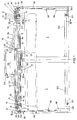
- Figure 1 diagrammatically shows a rear view, that is to say a view from within the vehicle in which the door system is mounted, of a swivel-sliding door system according to the invention.
- the swivel-sliding door system comprises two door leaves 1 and 2 which can be moved jointly in a direction transverse to the vehicle wall 3 ( Figure 2) and which can slide in opposite directions along the vehicle wall. It is pointed out that the invention can be used equally as well in the case of a single door leaf.
- the drive and guide means with the aid of which the movements needed to open and close the door leaves are executed and guided are, as usual, largely situated at the top of the door leaves.
- Said means comprise a bearing rail 4 which is still to be described in greater detail below and which can best be seen in plan view in Figure 2 and cross section in Figure 3.
- the bearing rail has a length which essentially corresponds to the width of the total door opening 5.
- the bearing rail acts together with a door leaf rail 6, 7 planted at the top edge of a door leaf via a roller system still to be described in greater detail.
- the door leaf rails are situated just below the bearing rail and are therefore not visible in Figure 2.
- the bearing rail is coupled to means which make possible a movement of the bearing rail, and consequently of the door leaves, transversely to the vehicle wall.
- Figures 1, 2 and 3 show roller supports 8, 9 which are situated near the ends of the bearing rail 4 and which extend transversely inwards, that is to say into the vehicle, from the bearing rail.
- the roller supports 8, 9 are each attached to the bearing rail by means of a flange 10, 11 and suitable attachment means such as, for example, screws.
- the roller supports each support two vertically oriented rollers 12, 13 which are situated in line one behind the other and rest on a running surface 14 of a roller guide member 15 which extends along each roller support 8 but is firmly joined to the vehicle.
- the rollers 12, 13 are rotatably attached to the support and the rollers can therefore roll over the running surface 14 in a direction transverse to the vehicle wall.
- the roller guide members 15 carry the weight of the guide rail and doors and are attached to the vehicle by means of bolts 16 which extend through openings 17 in a horizontal flange 18 formed on the side of each roller guide member 15 remote from the running track.
- the two roller guide members are mutually joined by a mounting plate 19 so that the two roller guide members and the mounting plate form an assembly unit.
- the openings 17 in the example shown are elongated, so that the position of the assembly unit can be accurately adjusted.
- the roller supports 8 are each also provided with at least one horizontal roller (not shown) which provides for the transverse guiding of the roller supports with respect to the roller guide members.
- the transverse rollers interact with a vertical running surface 20 adjacent to the horizontal running surface 14.
- the running surface of the vertical rollers can be profiled and interact with a complimentary profiled running surface of the roller guide member.
- roller supports 8 are each provided with a cam track 21 which is formed by two approximately concentric curved ribs 22, 23.
- a roller 24 which is mounted on the free end of a lever 25 engages between the ribs 22, 23.
- the other end of the lever 25 is provided with a transverse spindle 26 which can advantageously be supported in a supporting member 27 mounted on the associated roller guide member.
- the transverse spindle 26 also extends from the lever 25 in the direction of the door opening and is coupled for rotation to a drive motor 28. From a downwardly inclined and rearwardly directed position in Figure 3, the lever 25 can be rotated clockwise as seen in Figure 3, approximately a quarter of a revolution to a downwardly inclined and forwardly directed position as shown in Figure 4. At the same time, the rotary movement makes possible a forward displacement of the roller supports 8, 9, and therefore of the bearing rail 4 and the door leaves 1, 2, to a position shown in Figure 4, in which the bearing rail and the door leaves are situated outside the plane of the vehicle wall 3. In that position, the door leaves can be pushed along in front of the vehicle wall.
- Each door leaf is provided with a carrier 30, 31 which extends backwards and which is attached to the door leaf rail 6, 7 in the example shown.
- each carrier supports a nut member 32, 33 which interacts with an associated lead screw 34, 35 extending in the width direction of the door opening.
- the lead screws 34, 35 are coupled to one another via gears 36, 37 ( Figure 2), and have opposite directions of rotation and the same pitch.
- the gears are driven via a drive gear 38 which engages in the gear 36 in the example shown.
- the drive can also be such that the lead screws rotate in the same direction, provided the lead screws have an opposite pitch.
- the lead screws may, if desired, also be provided at the other ends with mutually engaging gears, but in the example shown, they are supported at the other ends (on the left in Figures 1 and 2) in a bearing support 39.
- one of the door leaves is provided with a roller which runs in a horizontal guide rail.
- the carrier 33 is provided at the top of a rearwardly extending flange 40 with a roller 41 which extends from the bottom into an inverted U-shaped guide rail 42.
- the guide rail extends largely parallel to the bearing rail 4 and is mounted against the bottom of the mounting plate 19. In the example shown, the guide rail extends above the left-hand part (seen in Figures 1 and 2) of the door opening. The end of the guide rail situated near the centre of the door opening is provided with a rearwardly curved arc-shaped part 43.
- the roller 41 In the closed state of the door leaves the roller 41 is situated near the free end of the arc-shaped part 43, as can be seen in Figures 2 and 5. As the door leaves are moved via the bearing rail 4 outside the plane of the vehicle wall, the roller 41 is forced to follow the curved part 43 of the guide rail 42. The door leaf 1 directly linked to the roller 41 consequently moves outwards and also to some extend to the left. This is only possible if the lead screw 35 rotates at the same time. As will be described in greater detail, the drive means are so designed that the lead screw 35 can in fact already rotate while the door leaves are moving out of the plane of the vehicle wall.
- the lead screw 35 is coupled via the gears 37 and 36 to the lead screw 34, the lead screw 34 also rotates at the same time, so that the other door leaf 2 makes a similar movement outwards and to the right.
- the door leaves can only move sideways along the vehicle wall if drive is continued. When the door is closed, the door leaves move in the opposite direction.
- the driving of the door leaves is provided by a drive motor 28 which is mounted on the mounting plate 19.
- the drive motor is preferably an electric motor.
- the spindle 50 of the motor 28 is coupled via a cardan spindle transmission 52 to the spindle 53 of the drive gear 38 already described.
- the spindle 53 is supported in a bearing support 54 in which the ends of the lead screws provided with the gears 36 and 37 are also supported and which is attached to the bearing rail 4.
- the housing of the drive motor 28 is preferably mounted so as to be able to rotate through a predetermined angle. If, therefore, rotation of the spindle of the motor is obstructed, the motor housing will rotate in the opposite direction around spindle 50 as a result of the reactive force which occurs.
- the support of the motor housing is indicated diagrammatically by 55 in Figure 1.
- the motor housing is eccentrically coupled on either side via cardan spindles 56, 57 to the levers 25.
- the rotation of the spindle 50 of the motor is in the first instance essentially prevented as a consequence of the fact that the free end of the curved part 43 of the guide rail 42 prevents, or virtually prevents a sideways movement of the door leaves.
- the housing of a motor 28 therefore drives the levers 25 via the cardan spindles 56 and 57, as a result of which the roller supports 8 and 9 are able to move forward. As the roller supports move forward, a more pronounced sideways movement of the door leaves becomes possible. As already stated, this movement should be accompanied by a rotation of the lead screws 34, 35.
- the motor housing may be directly linked to the cardan spindles 56, 57, but it is also possible to make use of a gear transmission or an intermediate lever or the like to transmit the rotation of the housing to the cardan spindles.
- the levers 25 rest against an end stop 38, at least in the closed position of the door.
- the curvature of the rib 22 and the position of the end stop 58 are chosen in such a way that the lever is pushed by the rib 22 in the direction of the end stop in the closed position of the door if a forward-directed force is exerted on the roller supports.
- a forward-directed force may be the consequence of passengers leaning against the door leaves or of suction forces acting on the door leaves.
- a second stop 59 is present for the other end position of the lever 25, which second end stop 59 achieves the result that the bearing rail moves just as far out of the plane of the vehicle wall at the ends as corresponds to the forward-directed component of the curved movement path of the roller 41 as is determined by the curved part 43 of the guide rail 42.
- the suspension of the door leaves on the bearing rail and the bearing rail itself will now be described in greater detail.
- the function of the bearing rail is to carry the door leaves in the forward-and backward-directed movement transversely to the vehicle wall 3.
- the bearing rail is used, moreover, to make possible the sideways movement of the door leaves along the vehicle wall.
- the door leaf suspension should be such that the doors are able to hang to some extent out of plumb, as shown in Figure 8.
- the tops of the door leaves must be moved out of the plane of the vehicle wall far enough for the bearing rail and the door rails to be situated completely outside the plane of the vehicle wall and on the other hand, the distance between the vehicle and the platform 80 must be as small as possible to prevent passengers getting caught between vehicle and platform. Both these requirements can be fulfilled if the door leaves hang to some extent out of plumb in the open position, as is shown exaggeratedly in Figure 8.
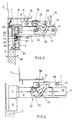
- Figure 3 shows a cross section of the bearing rail 4 and a door rail 6 situated underneath.
- the bearing rail 4 and the door rail 6 are essentially similar in shape and both have the form of a horizontal letter U in cross section.
- the bearing rail 4 also has an additional hanging flange, but this is not essential.
- a corresponding upright flange could be formed on the door rail.
- Formed on the lowermost horizontal limb of the two rails is a running surface 60 or 61, respectively, which is convex in cross section, for bearing and supporting rollers. Rollers 62 having a concave running surface interact with the running surface 60.
- rollers 62 spaced apart from one another are used and these are supported by the convex running surface 60 of the bearing rail.
- a further two additional rollers 63 are also provided in the bearing rail.
- the additional rollers 63 interact with a running surface 64, likewise convex, which is formed opposite the running surface 60 on the uppermost limb of the U-shaped.
- the additional rollers 63 are placed somewhat higher than the rollers 62.
- rollers 62, 63 are supported in a bearing plate which in this example is approximately lozenge-shaped and which, as a consequence of the additional rollers cannot tilt in its own plane and, as a consequence of the convex running surfaces 60, 64 and the complementarily shaped rollers 62, 63 can also not tilt in the transverse direction.
- the bearing plate 65 extends downwards to a position alongside the door rail 6 situated underneath the bearing rail and is provided in the vicinity of the lower edge with door rollers 66, 67 which are mounted in offset position with respect to the rollers 62, 63.
- the rollers 67 are again rollers which have a concave running surface and which interact with a complementarily shaped convex running surface 68 of the uppermost limb of the door rail. Since the door is suspended on the door rail, the rollers 67 are bearing rollers.
- the rollers 66 are supporting rollers which counteract tilting in the plane of the door. For this purpose, the rollers 66 are placed somewhat lower than the rollers 67. In addition, the rollers 66 have a convex running surface.
- the bearing rail and the door rails are moreover coupled to one another by a coupling strip 69 which extends in the longitudinal direction between the rails and which extends into the longitudinal grooves 70, 71 in the uppermost limb of the door rail and the lowermost limb of the bearing rail.
- the coupling strip 69 is mounted in a fixed manner in the door rail and, as a result of the use of a shoulder, it cannot move upwards out of the groove 70.
- the uppermost part of the coupling strip 69 extends with a certain amount of clearance into the groove 71 in the bearing rail, as a result of which the tilting movement indicated by an arrow 68 remains possible. Said tilting movement takes place around an imaginary axis which is situated precisely between the rails in the coupling strip. The tilting movement also makes it possible to absorb manufacturing tolerances and the like.
- Part A in Figure 7 shows one end of the bearing rail 4 with a door rail 6 situated underneath in the closed state of the door, while part B shows the position of the rails 4 and 6 and the bearing plate 65 with the various bearing and supporting rollers in the case of an open door.
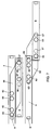
- Figures 1, 6 and 9 diagrammatically show the way in which the door leaves can be guided and driven at the bottom. Only the drive for the swivel movement of the door leaves needs to be transmitted at the bottom. The sliding movement is already adequately transmitted to the door leaves at the top.
- the levers 25 driven by the cardan spindle 56 have, as described above, a spindle 26 ( Figure 1) which is supported in a supporting member 27.
- Each spindle 26 extends past the associated supporting member 27 and past the horizontal flange 18 of the roller guide member 15.
- the free edge of the horizontal flange 18 is provided with an overhanging flange 90.
- the free end of the spindle 26 supports a lever 91 which extends along the face of the overhanging flange 90 and which, moreover, is coupled via a coupling strip 92 to a tilting piece 93 which is mounted so as to rotate around a spindle 94 extending transversely to the flange 90.
- the coupling piece is approximately triangular, one vertex of the triangular shape being directed downwards and the spindle 94 being situated in the vicinity of the downwardly directed vertex.
- the coupling strip is coupled by means of one uppermost vertex and is pivotably linked in the vicinity of the other vertex to the end of a vertical bar or tube 96, as shown at 95.
- Figure 6 shows that rotation of the lever 91 results in tilting of the tilting piece 93 around the spindle 94 and in upward or downward movement of the bar 96, as is shown diagrammatically by an arrow 97.
- the length of the bar 96 can be adjusted by screwing it in or out, as is shown diagrammatically in Figure 1 at 98.
- the lower end of the vertical bar 96 is coupled via a transmission device 99 to a swivel arm 100 whose free end supports a roller 101 which runs in an inverted U-shaped rail 102 mounted on the inside of the respective door leaf.
- the transmission device 99 is designed to convert a vertical movement into a rotary movement in the horizontal plane.
- An example of a suitable transmission device is shown diagrammatically, partly in section, in Figure 9.
- the transmission device shown comprises a vertically placed cylindrical housing 110 which is provided with one or more mounting flanges 111.
- a thicker rod or tube 112 in line with the bar 96 and coupled thereto extends into the housing 110.
- the rod or tube is provided with a first set of cams or rollers 113, 114 which extend on either side into vertical grooves 115, 116 in a bush 117 mounted in a fixed manner in the housing.
- the rod or tube 112 is able to move upwards and downwards in a vertical direction in the bush 117.
- a second bush 118 Mounted in line with the bush 117 is a second bush 118, which is, however, supported so as to rotate in the housing 110.
- the second bush is provided moreover, with two mutually oppositely situated, approximately helical grooves 119, 120 which, in this example, occupy an approximately 90° path. Extending into the grooves 119, 120 are again rollers or cams 121, 122 which are mounted on the rod or tube 112.
- the rod 112 When the rod 96 moves downwards out of the position shown, the rod 112 also moves downwards. As a consequence of the rollers 113, 114 extending into the grooves 115, 116, the rod is unable to rotate. The rollers 121, 122 therefore also move in a purely vertical direction. The bush 118 is then caused to rotate by the curved grooves 119, 120. The bush 118 is linked in a fixed manner to the swivel arm 100 as shown at 123 and the swivel arm therefore follows the rotation of bush 118. The length of the swivel arm and the angle of rotation permitted by the curved grooves 119, 120 determine the distance through which the door leaves can swivel outwards at the bottom. This distance can therefore be adjusted precisely by means of the shape of the grooves.
Landscapes
- Engineering & Computer Science (AREA)
- Mechanical Engineering (AREA)
- Power-Operated Mechanisms For Wings (AREA)
- Support Devices For Sliding Doors (AREA)
- Lock And Its Accessories (AREA)
Abstract
Description
- The invention relates to a swivel-sliding door system for a vehicle, having at least one door leaf situated in the vehicle wall in the closed state, and situated on the outside in front of the vehicle wall in the open state and leaving the door opening free under these circumstances, drive means, and transverse guide means and longitudinal guide means being provided which make possible a movement of the at least one door leaf transversely with respect to the vehicle wall and along the vehicle wall.
- Such swivel-sliding door systems have already been used for many years in, for example, train carriages for passenger transportation. An example of a known swivel-sliding door system is described in
European Patent Application 0 259 568. - A swivel-sliding door system should make possible the above described movements of the at least one door and should also provide a locking of the at least one door in the closed state which is such that the door cannot be opened by the suction action of air flows past the travelling carriage or by passengers leaning against the door. In addition, as compact a construction as possible is desirable so that the drive and guide means occupy a relatively little space. It is also desirable that the component parts of a swivel-sliding door system can as far as possible be preassembled.
- The object of the invention is to provide a swivel-sliding door system which fulfils the requirements stated above. More generally, the object of the invention is to provide a reliably operating, low-maintenance, and robustly and compactly constructed swivel-sliding door system which is relatively easy to assemble.
- According to the invention, a swivel-sliding door system of the type described above is characterised in that the longitudinal guide means comprise a bearing rail which extends over essentially the entire width of the door opening and is coupled to drive members which can cause the bearing rail to execute a movement transversely to the vehicle wall, the bearing rail being provided with a first set of rollers which run in the bearing rail and are supported on spindles which are mounted on a coupling member extending beyond the bottom of the bearing rail, which coupling member is provided with a second set of rollers which are situated in a lower position and interact with a door rail situated under the bearing rail and attached to the top of the door leaf.
- The invention will be described in greater detail below by reference to the accompanying drawing of an exemplary embodiment.
- Figure 1 shows diagrammatically a rear view of an exemplary embodiment of a swivel-sliding door system according to the invention having two door leaves in the closed state;
- Figure 2 diagrammatically shows a plan view of the system of Figure 1;
- Figure 3 shows a section along the line III-III in Figure 1;
- Figure 4 shows a section corresponding to Figure 3, with the doors in the pushed-out state;
- Figure 5 shows a section along the line V-V in Figure 1;
- Figure 6 shows a section along the line VI-VI in Figure 1;
- Figure 7 diagrammatically shows a detail of the door leaf suspension in the closed and in the open position of a door leaf;
- Figure 8 diagrammatically shows a cross section of a train carriage with open doors; and
- Figure 9 shows a detail of the door operating means at the bottom of a door leaf.
- Figure 1 diagrammatically shows a rear view, that is to say a view from within the vehicle in which the door system is mounted, of a swivel-sliding door system according to the invention. In the example shown, the swivel-sliding door system comprises two
door leaves - The drive and guide means with the aid of which the movements needed to open and close the door leaves are executed and guided are, as usual, largely situated at the top of the door leaves.
- Said means comprise a
bearing rail 4 which is still to be described in greater detail below and which can best be seen in plan view in Figure 2 and cross section in Figure 3. The bearing rail has a length which essentially corresponds to the width of the total door opening 5. In the example shown, the bearing rail acts together with adoor leaf rail - The bearing rail is coupled to means which make possible a movement of the bearing rail, and consequently of the door leaves, transversely to the vehicle wall. Figures 1, 2 and 3 show roller supports 8, 9 which are situated near the ends of the
bearing rail 4 and which extend transversely inwards, that is to say into the vehicle, from the bearing rail. The roller supports 8, 9 are each attached to the bearing rail by means of aflange - In this example, the roller supports each support two vertically
oriented rollers surface 14 of aroller guide member 15 which extends along eachroller support 8 but is firmly joined to the vehicle. Therollers surface 14 in a direction transverse to the vehicle wall. - Via the rollers, the
roller guide members 15 carry the weight of the guide rail and doors and are attached to the vehicle by means ofbolts 16 which extend throughopenings 17 in ahorizontal flange 18 formed on the side of eachroller guide member 15 remote from the running track. The two roller guide members are mutually joined by amounting plate 19 so that the two roller guide members and the mounting plate form an assembly unit. Theopenings 17 in the example shown are elongated, so that the position of the assembly unit can be accurately adjusted. - Preferably, the
roller supports 8 are each also provided with at least one horizontal roller (not shown) which provides for the transverse guiding of the roller supports with respect to the roller guide members. The transverse rollers interact with avertical running surface 20 adjacent to thehorizontal running surface 14. As an alternative, the running surface of the vertical rollers can be profiled and interact with a complimentary profiled running surface of the roller guide member. - At the side remote from the associated roller guide member, the
roller supports 8 are each provided with acam track 21 which is formed by two approximately concentriccurved ribs roller 24 which is mounted on the free end of alever 25 engages between theribs lever 25 is provided with atransverse spindle 26 which can advantageously be supported in a supportingmember 27 mounted on the associated roller guide member. - The
transverse spindle 26 also extends from thelever 25 in the direction of the door opening and is coupled for rotation to adrive motor 28. From a downwardly inclined and rearwardly directed position in Figure 3, thelever 25 can be rotated clockwise as seen in Figure 3, approximately a quarter of a revolution to a downwardly inclined and forwardly directed position as shown in Figure 4. At the same time, the rotary movement makes possible a forward displacement of the roller supports 8, 9, and therefore of thebearing rail 4 and thedoor leaves vehicle wall 3. In that position, the door leaves can be pushed along in front of the vehicle wall. - The movement of the door leaves along the vehicle wall can be achieved in various ways known for the purpose. According to the invention, use is preferably made of a lead screw drive for this purpose. Each door leaf is provided with a
carrier door leaf rail - The top of each carrier supports a
nut member lead screw lead screws gears 36, 37 (Figure 2), and have opposite directions of rotation and the same pitch. The gears are driven via adrive gear 38 which engages in thegear 36 in the example shown. The drive can also be such that the lead screws rotate in the same direction, provided the lead screws have an opposite pitch. - The lead screws may, if desired, also be provided at the other ends with mutually engaging gears, but in the example shown, they are supported at the other ends (on the left in Figures 1 and 2) in a
bearing support 39. - In order to determine the movement of the door leaves accurately, one of the door leaves is provided with a roller which runs in a horizontal guide rail. In the example shown, the
carrier 33 is provided at the top of a rearwardly extendingflange 40 with aroller 41 which extends from the bottom into an invertedU-shaped guide rail 42. - The guide rail extends largely parallel to the
bearing rail 4 and is mounted against the bottom of themounting plate 19. In the example shown, the guide rail extends above the left-hand part (seen in Figures 1 and 2) of the door opening. The end of the guide rail situated near the centre of the door opening is provided with a rearwardly curved arc-shaped part 43. - In the closed state of the door leaves the
roller 41 is situated near the free end of the arc-shaped part 43, as can be seen in Figures 2 and 5. As the door leaves are moved via thebearing rail 4 outside the plane of the vehicle wall, theroller 41 is forced to follow thecurved part 43 of theguide rail 42. Thedoor leaf 1 directly linked to theroller 41 consequently moves outwards and also to some extend to the left. This is only possible if thelead screw 35 rotates at the same time. As will be described in greater detail, the drive means are so designed that thelead screw 35 can in fact already rotate while the door leaves are moving out of the plane of the vehicle wall. Since thelead screw 35 is coupled via thegears lead screw 34, thelead screw 34 also rotates at the same time, so that theother door leaf 2 makes a similar movement outwards and to the right. As soon as the right-hand part of the guide rail has been reached, the door leaves can only move sideways along the vehicle wall if drive is continued. When the door is closed, the door leaves move in the opposite direction. - The driving of the door leaves is provided by a
drive motor 28 which is mounted on the mountingplate 19. The drive motor is preferably an electric motor. Thespindle 50 of themotor 28 is coupled via acardan spindle transmission 52 to thespindle 53 of thedrive gear 38 already described. Thespindle 53 is supported in abearing support 54 in which the ends of the lead screws provided with thegears bearing rail 4. - According to a more detailed elaboration of the invention, the housing of the
drive motor 28 is preferably mounted so as to be able to rotate through a predetermined angle. If, therefore, rotation of the spindle of the motor is obstructed, the motor housing will rotate in the opposite direction aroundspindle 50 as a result of the reactive force which occurs. The support of the motor housing is indicated diagrammatically by 55 in Figure 1. - The motor housing is eccentrically coupled on either side via
cardan spindles levers 25. - If the
motor 28 is energised in order to open the door, the rotation of thespindle 50 of the motor is in the first instance essentially prevented as a consequence of the fact that the free end of thecurved part 43 of theguide rail 42 prevents, or virtually prevents a sideways movement of the door leaves. The housing of amotor 28 therefore drives thelevers 25 via thecardan spindles cardan spindle 51 coupled to the motor spindle as a consequence of the fact that thecurved part 43 of the guide rail also prevents the forward-directed movement to some extent. It has been found that as a result of using a motor with a rotatably suspended housing and a driven spindle, the housing bringing about in the manner described the forward-and-backward-directed movement of the door leaves and the spindle the sideways movement, these two movements, which are at right angles to one another, smoothly merge into one another when controlled by a suitably shaped curved guide rail section and a cam which runs therein, is linked to a door leaf and is preferably constructed as a roller. - The motor housing may be directly linked to the
cardan spindles - The
levers 25 rest against anend stop 38, at least in the closed position of the door. Preferably, the curvature of therib 22 and the position of theend stop 58 are chosen in such a way that the lever is pushed by therib 22 in the direction of the end stop in the closed position of the door if a forward-directed force is exerted on the roller supports. Such a force may be the consequence of passengers leaning against the door leaves or of suction forces acting on the door leaves. - In the example shown, a
second stop 59 is present for the other end position of thelever 25, whichsecond end stop 59 achieves the result that the bearing rail moves just as far out of the plane of the vehicle wall at the ends as corresponds to the forward-directed component of the curved movement path of theroller 41 as is determined by thecurved part 43 of theguide rail 42. - The suspension of the door leaves on the bearing rail and the bearing rail itself will now be described in greater detail. The function of the bearing rail is to carry the door leaves in the forward-and backward-directed movement transversely to the
vehicle wall 3. The bearing rail is used, moreover, to make possible the sideways movement of the door leaves along the vehicle wall. Finally, the door leaf suspension should be such that the doors are able to hang to some extent out of plumb, as shown in Figure 8. On the one hand, the tops of the door leaves must be moved out of the plane of the vehicle wall far enough for the bearing rail and the door rails to be situated completely outside the plane of the vehicle wall and on the other hand, the distance between the vehicle and theplatform 80 must be as small as possible to prevent passengers getting caught between vehicle and platform. Both these requirements can be fulfilled if the door leaves hang to some extent out of plumb in the open position, as is shown exaggeratedly in Figure 8. - The door leaf suspension is shown in greater detail in Figures 3 and 7. Figure 3 shows a cross section of the bearing
rail 4 and adoor rail 6 situated underneath. The bearingrail 4 and thedoor rail 6 are essentially similar in shape and both have the form of a horizontal letter U in cross section. In this example, the bearingrail 4 also has an additional hanging flange, but this is not essential. A corresponding upright flange could be formed on the door rail. Formed on the lowermost horizontal limb of the two rails is a runningsurface Rollers 62 having a concave running surface interact with the runningsurface 60. As can be seen in Figure 7 tworollers 62 spaced apart from one another are used and these are supported by theconvex running surface 60 of the bearing rail. Also provided in the bearing rail are a further twoadditional rollers 63, likewise having a concave running surface. Theadditional rollers 63 interact with a runningsurface 64, likewise convex, which is formed opposite the runningsurface 60 on the uppermost limb of the U-shaped. For this purpose, theadditional rollers 63 are placed somewhat higher than therollers 62. Therollers rollers - The bearing
plate 65 extends downwards to a position alongside thedoor rail 6 situated underneath the bearing rail and is provided in the vicinity of the lower edge withdoor rollers rollers rollers 67 are again rollers which have a concave running surface and which interact with a complementarily shapedconvex running surface 68 of the uppermost limb of the door rail. Since the door is suspended on the door rail, therollers 67 are bearing rollers. Therollers 66 are supporting rollers which counteract tilting in the plane of the door. For this purpose, therollers 66 are placed somewhat lower than therollers 67. In addition, therollers 66 have a convex running surface. This means that the door leaf can tilt sideways to some extent with respect to the supportingrollers 66, as is indicated by an arrow P. Theconcave rollers 67 do not prevent this since they are only in contact with the complementarily shaped convex running surface of the uppermost limb of the door rail. - The bearing rail and the door rails are moreover coupled to one another by a
coupling strip 69 which extends in the longitudinal direction between the rails and which extends into thelongitudinal grooves coupling strip 69 is mounted in a fixed manner in the door rail and, as a result of the use of a shoulder, it cannot move upwards out of thegroove 70. The uppermost part of thecoupling strip 69 extends with a certain amount of clearance into thegroove 71 in the bearing rail, as a result of which the tilting movement indicated by anarrow 68 remains possible. Said tilting movement takes place around an imaginary axis which is situated precisely between the rails in the coupling strip. The tilting movement also makes it possible to absorb manufacturing tolerances and the like. - Part A in Figure 7 shows one end of the bearing
rail 4 with adoor rail 6 situated underneath in the closed state of the door, while part B shows the position of therails plate 65 with the various bearing and supporting rollers in the case of an open door. - Figures 1, 6 and 9 diagrammatically show the way in which the door leaves can be guided and driven at the bottom. Only the drive for the swivel movement of the door leaves needs to be transmitted at the bottom. The sliding movement is already adequately transmitted to the door leaves at the top.
- The
levers 25 driven by thecardan spindle 56 have, as described above, a spindle 26 (Figure 1) which is supported in a supportingmember 27. Eachspindle 26 extends past the associated supportingmember 27 and past thehorizontal flange 18 of theroller guide member 15. The free edge of thehorizontal flange 18 is provided with an overhangingflange 90. The free end of thespindle 26 supports alever 91 which extends along the face of the overhangingflange 90 and which, moreover, is coupled via acoupling strip 92 to atilting piece 93 which is mounted so as to rotate around aspindle 94 extending transversely to theflange 90. In the example shown, the coupling piece is approximately triangular, one vertex of the triangular shape being directed downwards and thespindle 94 being situated in the vicinity of the downwardly directed vertex. The coupling strip is coupled by means of one uppermost vertex and is pivotably linked in the vicinity of the other vertex to the end of a vertical bar ortube 96, as shown at 95. - Figure 6 shows that rotation of the
lever 91 results in tilting of the tiltingpiece 93 around thespindle 94 and in upward or downward movement of thebar 96, as is shown diagrammatically by anarrow 97. The length of thebar 96 can be adjusted by screwing it in or out, as is shown diagrammatically in Figure 1 at 98. - The lower end of the
vertical bar 96 is coupled via atransmission device 99 to aswivel arm 100 whose free end supports aroller 101 which runs in an invertedU-shaped rail 102 mounted on the inside of the respective door leaf. - The
transmission device 99 is designed to convert a vertical movement into a rotary movement in the horizontal plane. An example of a suitable transmission device is shown diagrammatically, partly in section, in Figure 9. The transmission device shown comprises a vertically placedcylindrical housing 110 which is provided with one or more mountingflanges 111. A thicker rod ortube 112 in line with thebar 96 and coupled thereto extends into thehousing 110. The rod or tube is provided with a first set of cams orrollers vertical grooves bush 117 mounted in a fixed manner in the housing. The rod ortube 112 is able to move upwards and downwards in a vertical direction in thebush 117. Mounted in line with thebush 117 is asecond bush 118, which is, however, supported so as to rotate in thehousing 110. The second bush is provided moreover, with two mutually oppositely situated, approximatelyhelical grooves grooves cams tube 112. - When the
rod 96 moves downwards out of the position shown, therod 112 also moves downwards. As a consequence of therollers grooves rollers bush 118 is then caused to rotate by thecurved grooves bush 118 is linked in a fixed manner to theswivel arm 100 as shown at 123 and the swivel arm therefore follows the rotation ofbush 118. The length of the swivel arm and the angle of rotation permitted by thecurved grooves - It is pointed out that, preceding from the above, various modifications are obvious to the person skilled in the art. Such modifications are deemed to fall within the scope of the invention.
Claims (30)
- Swivel-sliding door system for a vehicle having at least one door leaf situated in the vehicle wall in the closed state, and situated on the outside in front of the vehicle wall in the open state and leaving the door opening free under these circumstances, drive means, and transverse guide means and longitudinal guide means being provided which make possible a movement of at least one door leaf transversely with respect to the vehicle wall and along the vehicle wall, characterised in that the longitudinal guide means comprise a bearing rail (4) which extends over essentially the entire width of the door opening and is coupled to drive members which can cause the bearing rail to execute a movement transversely to the vehicle wall (3), the bearing rail being provided with a first set of rollers (62, 63) which run in the bearing rail and are supported on spindles which are mounted on a coupling member extending beyond the bottom of the bearing rail, which coupling member is provided with a second set of rollers (66, 67) which are situated in a lower position and interact with a door rail (6) situated under the bearing rail and attached to the top of the door leaf (1, 2).
- Swivel-sliding door system according to Claim 1 characterised in that the coupling member (65) provided with rollers is an approximately lozenge-shaped plate.
- Swivel-sliding door system according to Claim 1 or 2 characterised in that the bearing rail and the door rail both comprise a horizontal, essentially U-shaped profile in which the mutually facing surfaces of both the lowermost limbs and the uppermost limbs of the U-shapes of the rails form roller running surfaces.
- Swivel-sliding door system according to Claim 3, characterised in that the first set of rollers comprises at least one bearing roller running on the running surface of the lowermost limb of the bearing rail and at least one supporting roller interacting with the running surface of the uppermost limb of the bearing rail.
- Swivel-sliding door system according to Claim 3 or 4, characterised in that the second set of rollers comprises at least one bearing roller interacting with the running surface of the uppermost limb of the door rail and at least one supporting roller interacting with the running surface of the lowermost limb of the door rail.
- Swivel-sliding door system according to one of Claims 3 to 5 inclusive, characterised in that the roller running surfaces of the bearing rail and of the door rail are surfaces which are convex in cross section, and in that the bearing and supporting rollers (62, 63) running in the bearing rail have a complementarily shaped concave running surface.
- Swivel-sliding door system according to Claim 6, characterised in that the bearing rollers extending into a door rail have a concave running surface, while the supporting rollers extending into a door rail have a convex running surface.
- Swivel-sliding door system according to one of the preceding claims, characterised in that the lowermost limb of the bearing rail is provided in the lower side, remote from the running surface thereof, with a longitudinal groove into which a coupling strip (69) loosely extends, which coupling strip (69) is mounted in a groove provided in the opposite surface of the uppermost limb of a door rail.
- Swivel-sliding door system according to one the preceding claims, characterised in that the drive members which can cause the bearing rail to move transversely to the vehicle wall comprise roller supports (8, 9) which are linked to the bearing rail near the ends of the bearing rail, and extend essentially horizontally rearwards, which roller supports are provided with a number of rollers which interact with at least one running surface (14) of a roller guide member (15) mounted in a fixed manner, drive members (25) which act on the roller supports moreover being provided.
- Swivel-sliding door system according to Claim 9, characterised in that the drive members which act on a roller support (8, 9) comprise a drive lever, one end of which is mounted outside the roller support on a drivable spindle and the free end of which is able to move along the roller support, the roller support being provided with a groove in which a cam (24) mounted on the free end of the lever engages.
- Swivel-sliding door system according to Claim 10, characterised in that the groove is formed by two curved ribs (22, 23) which are formed with a gap on the roller support.
- Swivel-sliding door system according to Claim 10 or 11 characterized in that the cam is a rotatable roller.
- Swivel-sliding door system according to one of Claims 10 to 12 inclusive, characterized in that the drivable spindle is mounted on the adjacent roller guide member.
- Swivel-sliding door system according to one of Claims 10 to 13 inclusive, characterized in that the roller guide member is provided with at least one end stop (58, 59) for the drive lever.
- Swivel-sliding door system according to one of Claims 9 to 14, characterized in that the roller guide members have, on the side remote from the adjacent roller supports, an essentially horizontal flange via which the roller guide members are joined to the vehicle.
- Swivel-sliding door system according to one of Claims 9 to 15 inclusive, characterized in that the roller guide members are linked on either side of a door opening by a mounting plate (19).
- Swivel-sliding door system according to one of the preceding claims, characterised in that each door rail is provided with a carrier (30, 31) which extends into the vehicle and which supports a nut member (32, 33) which interacts with a drive lead screw (34, 35) which extends parallel to and behind the bearing rail.
- Swivel-sliding door system according to Claim 17, characterised in that a separate drive lead screw is provided for each door leaf, and in that each drive lead screw is provided at at least one of the ends, with a gear which is linked to a driving gear.
- Swivel-sliding door system according to Claim 18, characterised in that two door leaves having associated drive lead screws are provided, and in that both drive lead screws are provided with a gear which engages in the gear of the other drive lead screw, and in that one of the gears interacts with a driving gear.
- Swivel-sliding door system according to one of Claims 17 to 19 inclusive, characterised in that at least one of the carriers is provided with a roller (41) which extends into a guide rail having a straight section and a curved end.
- Swivel-sliding door system according to Claim 16 and 17, characterised in that the guide rail is mounted against the bottom of the mounting plate.
- Swivel-sliding door system according to one of Claims 10 to 21 inclusive, characterised in that the drivable spindles of the drive levers (25) are each coupled via a cardan spindle (56, 57) with a drive motor (23).
- Swivel-sliding door system according to one of Claims 18 to 22 characterised in that the driving gear for the drive lead screws is coupled to the drive motor (28) via a cardan spindle (51).
- Swivel-sliding door system according to Claim 22 and 23, characterised in that the drive motor for the drive levers is the same motor as the drive motor for the drive lead screws, the motor housing being rotatably mounted and being coupled to the drive levers, while the motor spindle is coupled to the drive gear for the drive lead screws.
- Swivel-sliding door system according to Claim 24, characterised in that the drive motor is an electric motor.
- Swivel-sliding door system according to Claim 24 or 25, characterised in that the drive motor (28) is mounted on the mounting plate (19).
- Swivel-sliding door system according to one of the preceding claims, characterised by at least one essentially vertical bar or tube (96) whose upper end is coupled to drive members which are able to cause the rod or tube to execute an upward or downward movement and whose lower end interacts with a transmission device 99 which is capable of converting a vertical movement into a rotation in a horizontal plane of a swivel arm whose free end supports a cam (101) which engages in a guide rail (102) mounted on a door leaf.
- Swivel-sliding door system according to Claim 27, characterised in that the drive members comprise a lever (91) coupled to a tilting piece (93).
- Swivel-sliding door system according to Claim 28, characterised in that said lever (91) is mounted on the spindle (26) of a drive lever (25) for a roller support (8, 9).
- Swivel-sliding door system according to one of Claims 27 to 29 inclusive, characterised in that the transmission device comprises a fixed bush having at least one vertical groove and a rotatable bush situated in line with the fixed bush and having at least one curved groove, the rotatable bush being linked to the swivel arm; in that a tube or bar extends into the fixed and the rotatable bush and is provided with cams, projecting sideways, which extend into the grooves, which tube or bar can move upwards and downwards under the control of the rod (96), as a result of which the rotatable bush is caused to rotate.
Applications Claiming Priority (3)
| Application Number | Priority Date | Filing Date | Title |
|---|---|---|---|
| NL9100951A NL9100951A (en) | 1991-06-03 | 1991-06-03 | SWING SLIDING DOOR SYSTEM FOR A VEHICLE. |
| NL9100951 | 1991-06-03 | ||
| CA002076261A CA2076261C (en) | 1991-06-03 | 1992-08-17 | Swivel-sliding door system for a vehicle |
Publications (2)
| Publication Number | Publication Date |
|---|---|
| EP0517334A1 true EP0517334A1 (en) | 1992-12-09 |
| EP0517334B1 EP0517334B1 (en) | 1995-09-06 |
Family
ID=25675444
Family Applications (1)
| Application Number | Title | Priority Date | Filing Date |
|---|---|---|---|
| EP92201601A Expired - Lifetime EP0517334B1 (en) | 1991-06-03 | 1992-06-03 | Swivel-sliding door system for a vehicle |
Country Status (7)
| Country | Link |
|---|---|
| US (1) | US5253452A (en) |
| EP (1) | EP0517334B1 (en) |
| AT (1) | ATE127409T1 (en) |
| CA (1) | CA2076261C (en) |
| DE (1) | DE69204556T2 (en) |
| ES (1) | ES2079784T3 (en) |
| NL (1) | NL9100951A (en) |
Cited By (17)
| Publication number | Priority date | Publication date | Assignee | Title |
|---|---|---|---|---|
| EP0820889A1 (en) * | 1996-07-24 | 1998-01-28 | Sab Wabco B.V. | Swivel-sliding door system for a vehicle |
| EP0875434A1 (en) * | 1997-04-28 | 1998-11-04 | IFE Industrie-Einrichtungen Fertigungs-Aktiengesellschaft | Pivoting and sliding door for passenger transporting vehicles |
| ES2182605A1 (en) * | 1998-11-20 | 2003-03-01 | Com E Ind Repro S L | Operating mechanism for sliding door, comprises fixed motor unit driving either opening or closing roller, bearing on door's friction track, impelling door along fixed guide channel |
| EP1314626A1 (en) * | 2001-11-27 | 2003-05-28 | Gebrüder Bode GmbH & Co.KG | Pivotable sliding door for vehicles , especially passenger door for urban passenger traffic vehicles |
| WO2004065154A1 (en) * | 2003-01-21 | 2004-08-05 | Knorr-Bremse Ges.M.B.H. | Pivoting sliding door for vehicles |
| WO2004103750A1 (en) * | 2003-05-20 | 2004-12-02 | Daimlerchrysler Ag | Exterior sliding door for a vehicle |
| DE10327982A1 (en) * | 2003-06-21 | 2005-01-20 | Hübner GmbH | Outward movement/sliding door system for vehicle has drive movably mounted on mounting plate that causes both outward movement and lateral displacement of door panel |
| EP1527975A1 (en) * | 2003-10-31 | 2005-05-04 | Gebr. Bode GmbH & Co. KG | Sliding and plugging door, especially passenger door for mass transit vehicles |
| WO2005103429A3 (en) * | 2004-04-23 | 2006-01-05 | Knorr Bremse Gmbh | Locking device |
| DE102005005802B3 (en) * | 2005-02-09 | 2006-06-14 | Hübner GmbH | Sliding door system for vehicles has chain drive that exhibits transmission such that outgoing motion of carriage slows down with high torque and lateral motion of door leaf increases faster with low torque |
| EP2325424A2 (en) | 2009-11-24 | 2011-05-25 | Masats, S.A. | Mechanism for closing and opening a swinging-sliding door leaf |
| DE202012100077U1 (en) | 2011-01-11 | 2012-02-27 | Manfred Teufl | Sliding door system for vehicles |
| EP2348181A4 (en) * | 2008-10-17 | 2013-12-04 | Nabtesco Corp | RECESSED DOOR DEVICE |
| KR101450376B1 (en) * | 2010-07-30 | 2014-10-14 | 한국산업은행 | Plug door system |
| KR101450366B1 (en) * | 2010-12-31 | 2014-10-14 | 한국산업은행 | Plug door system |
| RU2538915C2 (en) * | 2010-09-28 | 2015-01-10 | Гебр. Боде Гмбх Унд Ко. Кг | Modular door operating gear |
| WO2022017676A1 (en) * | 2020-07-21 | 2022-01-27 | Gebr. Bode Gmbh & Co. Kg | Door system for a vehicle, and vehicle comprising a door system |
Families Citing this family (18)
| Publication number | Priority date | Publication date | Assignee | Title |
|---|---|---|---|---|
| US5906071A (en) * | 1995-07-12 | 1999-05-25 | Itt Automotive Electrical Systems, Inc. | Rear-center-mounted power door actuator |
| US5644869A (en) * | 1995-12-20 | 1997-07-08 | Itt Automotive Electrical Systems, Inc. | Power drive for a movable closure with ball nut drive screw |
| US5787636A (en) * | 1995-12-20 | 1998-08-04 | Itt Automotive Electrical Systems, Inc. | Power drive for a movable closure with ball nut driven flexible cable |
| US6134838A (en) * | 1997-02-24 | 2000-10-24 | Westinghouse Air Brake Company | Power door having a drive member disposed within a hanger portion and rollers of a door support engaging the hanger portion for motion therealong |
| US6061961A (en) * | 1999-06-18 | 2000-05-16 | Rupe; Maurice J. | Swinging security door |
| US6336248B1 (en) * | 2000-05-05 | 2002-01-08 | Kason Industries, Inc. | Suspension system for sliding door |
| US20020092236A1 (en) * | 2000-09-14 | 2002-07-18 | Heffner Steven P. | Drive system |
| WO2004022894A1 (en) | 2002-09-03 | 2004-03-18 | Rytec Corporation | Dual overhead track for a sliding door |
| DE202011002810U1 (en) | 2011-02-16 | 2011-06-09 | Inter Ikea Systems B.V. | Mechanism for sliding door |
| ITTV20110070A1 (en) * | 2011-05-23 | 2012-11-24 | Bortoluzzi Lab S R L | DEVICE FOR SLIDING DOORS WITH COMPLANAR CLOSING, PARTICULARLY FOR FURNITURE AND SIMILAR |
| DE202013100356U1 (en) * | 2013-01-25 | 2014-04-28 | Gebr. Bode Gmbh & Co. Kg | Door arrangement with locking system |
| EP2889200B1 (en) * | 2013-12-30 | 2019-07-31 | Vapor Europe S.r.l. A Wabtec Company | Door drive device for a door of a wagon |
| CN103924900B (en) * | 2014-04-09 | 2015-12-30 | 江苏大学 | One draws movement mechanism apparatus based on virtual line moving guide rail stopping sliding door plug |
| JP2016028837A (en) * | 2014-07-25 | 2016-03-03 | ファナック株式会社 | Machine tool slide door |
| JP6356555B2 (en) | 2014-09-19 | 2018-07-11 | ナブテスコ株式会社 | Plug door opening and closing device and plug door device |
| ES2748048T3 (en) * | 2016-03-07 | 2020-03-12 | Isaf Bus Components S R L | Door system |
| DE102017123074A1 (en) * | 2017-10-05 | 2019-04-11 | Agtatec Ag | Automatic door system, in particular in the form of a sliding door or a telescopic sliding door or a folding door |
| KR20240079615A (en) * | 2022-11-29 | 2024-06-05 | 현대자동차주식회사 | Door open-close device for vehicle |
Citations (5)
| Publication number | Priority date | Publication date | Assignee | Title |
|---|---|---|---|---|
| FR2589938A1 (en) * | 1985-11-14 | 1987-05-15 | Faiveley Ets | SLIDING AND SPEAKING DOOR |
| EP0225855A2 (en) * | 1985-12-11 | 1987-06-16 | WABCO WESTINGHOUSE COMPAGNIA FRENI S.p.A. | Door for vehicles, particularly railway and underground train carriages |
| EP0259568A2 (en) * | 1986-09-05 | 1988-03-16 | IFE Industrie-Einrichtungen Fertigungs-Aktiengesellschaft | Swingable sliding door for vehicles |
| EP0320591A2 (en) * | 1987-12-12 | 1989-06-21 | Gebrüder Bode & Co. GmbH | Hinged slidable door for vehicles |
| EP0359640A1 (en) * | 1988-09-14 | 1990-03-21 | Faiveley S.A. | Device for guiding the removal and insertion of a wing from or into its frame, and door, especially for a rail vehicle, so equipped |
Family Cites Families (9)
| Publication number | Priority date | Publication date | Assignee | Title |
|---|---|---|---|---|
| DE662233C (en) * | 1936-01-24 | 1938-07-08 | Curt Stedefeld Dipl Ing | Device for guiding tightly closing sliding doors, especially for railroad cars |
| US3601926A (en) * | 1969-07-18 | 1971-08-31 | Kaiser Jeep Corp | Sliding door and support |
| GB1439940A (en) * | 1972-12-01 | 1976-06-16 | Westinghouse Brake & Signal | Door mechanisms |
| US3906668A (en) * | 1974-06-06 | 1975-09-23 | Plc Engineering Company Limite | Sliding plug door gear |
| FR2294306A1 (en) * | 1974-12-10 | 1976-07-09 | Faiveley Sa | LOUVOYANT MOVEMENT DOOR |
| FR2387343A2 (en) * | 1977-04-13 | 1978-11-10 | Faiveley Sa | LOUVOYANT MOVEMENT DOOR |
| IT1148041B (en) * | 1981-03-20 | 1986-11-26 | Nuova Agudio Spa | DEVICE FOR HANDLING THE DOOR WITH TWO SLIDING DOORS IN A CABIN OF A CONTINUOUS MOTORCYCLE CABLE WITH CLAMPING OR AUTOMATIC COUPLING |
| FI73043C (en) * | 1985-11-21 | 1987-08-10 | Euroshield Oy | Door in a structure that prevents displacement of interference fields. |
| DE58905915D1 (en) * | 1989-06-02 | 1993-11-18 | Ife Gmbh | Swivel sliding door for vehicles. |
-
1991
- 1991-06-03 NL NL9100951A patent/NL9100951A/en not_active Application Discontinuation
-
1992
- 1992-06-03 AT AT92201601T patent/ATE127409T1/en active
- 1992-06-03 DE DE69204556T patent/DE69204556T2/en not_active Expired - Lifetime
- 1992-06-03 EP EP92201601A patent/EP0517334B1/en not_active Expired - Lifetime
- 1992-06-03 ES ES92201601T patent/ES2079784T3/en not_active Expired - Lifetime
- 1992-08-14 US US07/931,035 patent/US5253452A/en not_active Expired - Lifetime
- 1992-08-17 CA CA002076261A patent/CA2076261C/en not_active Expired - Lifetime
Patent Citations (5)
| Publication number | Priority date | Publication date | Assignee | Title |
|---|---|---|---|---|
| FR2589938A1 (en) * | 1985-11-14 | 1987-05-15 | Faiveley Ets | SLIDING AND SPEAKING DOOR |
| EP0225855A2 (en) * | 1985-12-11 | 1987-06-16 | WABCO WESTINGHOUSE COMPAGNIA FRENI S.p.A. | Door for vehicles, particularly railway and underground train carriages |
| EP0259568A2 (en) * | 1986-09-05 | 1988-03-16 | IFE Industrie-Einrichtungen Fertigungs-Aktiengesellschaft | Swingable sliding door for vehicles |
| EP0320591A2 (en) * | 1987-12-12 | 1989-06-21 | Gebrüder Bode & Co. GmbH | Hinged slidable door for vehicles |
| EP0359640A1 (en) * | 1988-09-14 | 1990-03-21 | Faiveley S.A. | Device for guiding the removal and insertion of a wing from or into its frame, and door, especially for a rail vehicle, so equipped |
Cited By (30)
| Publication number | Priority date | Publication date | Assignee | Title |
|---|---|---|---|---|
| EP0820889A1 (en) * | 1996-07-24 | 1998-01-28 | Sab Wabco B.V. | Swivel-sliding door system for a vehicle |
| NL1003674C2 (en) * | 1996-07-24 | 1998-01-28 | Sab Wabco B V | Swing sliding door system for a vehicle. |
| US6385910B1 (en) | 1996-07-24 | 2002-05-14 | Pieter Smink | Swivel-sliding door system for a vehicle |
| EP0875434A1 (en) * | 1997-04-28 | 1998-11-04 | IFE Industrie-Einrichtungen Fertigungs-Aktiengesellschaft | Pivoting and sliding door for passenger transporting vehicles |
| ES2182605A1 (en) * | 1998-11-20 | 2003-03-01 | Com E Ind Repro S L | Operating mechanism for sliding door, comprises fixed motor unit driving either opening or closing roller, bearing on door's friction track, impelling door along fixed guide channel |
| ES2182603A1 (en) * | 1998-11-20 | 2003-03-01 | Com E Ind Repro S L | Operating mechanism for sliding door, comprises fixed motor unit driving either opening or closing roller, bearing on door's friction track, impelling door along fixed guide channel |
| EP1314626A1 (en) * | 2001-11-27 | 2003-05-28 | Gebrüder Bode GmbH & Co.KG | Pivotable sliding door for vehicles , especially passenger door for urban passenger traffic vehicles |
| DE10158094A1 (en) * | 2001-11-27 | 2003-07-24 | Bode Gmbh & Co Kg | Pivoting sliding door for vehicles, in particular passenger door for local public transport vehicles |
| AT500017B1 (en) * | 2003-01-21 | 2006-03-15 | Knorr Bremse Gmbh | SWIVEL SLIDING DOOR FOR VEHICLES |
| CN100434294C (en) * | 2003-01-21 | 2008-11-19 | 克诺尔-布里姆斯股份有限公司 | Rotary sliding door for a vehicle or elevator car |
| US7549251B2 (en) | 2003-01-21 | 2009-06-23 | Knorr-Bremse Ges.M.B.H. | Pivoting sliding doors for vehicles |
| RU2330766C2 (en) * | 2003-01-21 | 2008-08-10 | Кнорр-Бремзе Гез. М.Б.Х. | Rotary-sliding door for transport vehicles |
| AT500017A1 (en) * | 2003-01-21 | 2005-10-15 | Knorr Bremse Gmbh | SWIVEL SLIDING DOOR FOR VEHICLES |
| JP2006513088A (en) * | 2003-01-21 | 2006-04-20 | クノル−ブレムゼ ゲゼルシャフト ミット ベシュレンクテル ハフツング | Parallel glide doors used in vehicles |
| WO2004065154A1 (en) * | 2003-01-21 | 2004-08-05 | Knorr-Bremse Ges.M.B.H. | Pivoting sliding door for vehicles |
| WO2004103750A1 (en) * | 2003-05-20 | 2004-12-02 | Daimlerchrysler Ag | Exterior sliding door for a vehicle |
| DE10327982A1 (en) * | 2003-06-21 | 2005-01-20 | Hübner GmbH | Outward movement/sliding door system for vehicle has drive movably mounted on mounting plate that causes both outward movement and lateral displacement of door panel |
| EP1527975A1 (en) * | 2003-10-31 | 2005-05-04 | Gebr. Bode GmbH & Co. KG | Sliding and plugging door, especially passenger door for mass transit vehicles |
| US8113552B2 (en) | 2004-04-23 | 2012-02-14 | Knorr-Bremse Ges. M.B.H. | Locking device |
| WO2005103429A3 (en) * | 2004-04-23 | 2006-01-05 | Knorr Bremse Gmbh | Locking device |
| DE102005005802B3 (en) * | 2005-02-09 | 2006-06-14 | Hübner GmbH | Sliding door system for vehicles has chain drive that exhibits transmission such that outgoing motion of carriage slows down with high torque and lateral motion of door leaf increases faster with low torque |
| EP1690713A2 (en) | 2005-02-09 | 2006-08-16 | HÜBNER GmbH | System for sliding plug door for a vehicle |
| EP2348181A4 (en) * | 2008-10-17 | 2013-12-04 | Nabtesco Corp | RECESSED DOOR DEVICE |
| EP2325424A2 (en) | 2009-11-24 | 2011-05-25 | Masats, S.A. | Mechanism for closing and opening a swinging-sliding door leaf |
| KR101450376B1 (en) * | 2010-07-30 | 2014-10-14 | 한국산업은행 | Plug door system |
| RU2538915C2 (en) * | 2010-09-28 | 2015-01-10 | Гебр. Боде Гмбх Унд Ко. Кг | Modular door operating gear |
| KR101450366B1 (en) * | 2010-12-31 | 2014-10-14 | 한국산업은행 | Plug door system |
| DE202012100077U1 (en) | 2011-01-11 | 2012-02-27 | Manfred Teufl | Sliding door system for vehicles |
| WO2022017676A1 (en) * | 2020-07-21 | 2022-01-27 | Gebr. Bode Gmbh & Co. Kg | Door system for a vehicle, and vehicle comprising a door system |
| US12467298B2 (en) | 2020-07-21 | 2025-11-11 | Bode— Die Tür Gmbh | Door system for a vehicle and vehicle with a door system |
Also Published As
| Publication number | Publication date |
|---|---|
| DE69204556D1 (en) | 1995-10-12 |
| NL9100951A (en) | 1993-01-04 |
| EP0517334B1 (en) | 1995-09-06 |
| ES2079784T3 (en) | 1996-01-16 |
| CA2076261C (en) | 2002-11-19 |
| ATE127409T1 (en) | 1995-09-15 |
| CA2076261A1 (en) | 1994-02-18 |
| DE69204556T2 (en) | 1996-02-01 |
| US5253452A (en) | 1993-10-19 |
Similar Documents
| Publication | Publication Date | Title |
|---|---|---|
| EP0517334B1 (en) | Swivel-sliding door system for a vehicle | |
| US6385910B1 (en) | Swivel-sliding door system for a vehicle | |
| CA1054859A (en) | Oblique-displacement sliding door | |
| AU2008259431B2 (en) | Platform gate for train stations | |
| US6032762A (en) | Door operator for elevators having curved doors | |
| NO313710B1 (en) | Drive device for a revolving door with an electronic control | |
| WO2000012421A9 (en) | Wrap-around elevator door | |
| CA2219002A1 (en) | Swinging/sliding door for vehicles | |
| JP2002504200A (en) | Link device for a door rotatably mounted on the body of an automobile | |
| NO320608B1 (en) | Window or door arrangement for a building facade with a frame structure where a sliding window or a sliding door with a frame connected to the frame structure is mounted side by side. | |
| US6065247A (en) | Pivotable structure | |
| US5094501A (en) | Side door constructed as sliding door for passenger motor vehicles | |
| DE29801134U1 (en) | Power supply for a door leaf | |
| AU652465B2 (en) | Swivel-sliding door system for a vehicle | |
| GB2301811A (en) | Stairlift | |
| EP0408716B1 (en) | A railsystem for a chair lift or the like, which is mounted on or along a flight of stairs | |
| US3104911A (en) | Automatic swivel seat | |
| AU2003283301A1 (en) | Sliding wall | |
| JPH0681537A (en) | Window glass angle adjuster | |
| DE19702085A1 (en) | Door system for passenger aircraft | |
| US5081792A (en) | Window regulator with orthogonal pushout for flush window | |
| GB1597175A (en) | Sliding flush closing door for vehicles | |
| CN210554815U (en) | To opening door equipment and car | |
| CA2353936A1 (en) | Drive device for a sliding panel | |
| RU2030314C1 (en) | Turnable-sliding door of rail vehicle |
Legal Events
| Date | Code | Title | Description |
|---|---|---|---|
| PUAI | Public reference made under article 153(3) epc to a published international application that has entered the european phase |
Free format text: ORIGINAL CODE: 0009012 |
|
| AK | Designated contracting states |
Kind code of ref document: A1 Designated state(s): AT BE CH DE DK ES FR GB IT LI NL SE |
|
| 17P | Request for examination filed |
Effective date: 19930115 |
|
| 17Q | First examination report despatched |
Effective date: 19940624 |
|
| GRAA | (expected) grant |
Free format text: ORIGINAL CODE: 0009210 |
|
| AK | Designated contracting states |
Kind code of ref document: B1 Designated state(s): AT BE CH DE DK ES FR GB IT LI NL SE |
|
| PG25 | Lapsed in a contracting state [announced via postgrant information from national office to epo] |
Ref country code: DK Effective date: 19950906 |
|
| REF | Corresponds to: |
Ref document number: 127409 Country of ref document: AT Date of ref document: 19950915 Kind code of ref document: T |
|
| REF | Corresponds to: |
Ref document number: 69204556 Country of ref document: DE Date of ref document: 19951012 |
|
| ET | Fr: translation filed | ||
| ITF | It: translation for a ep patent filed | ||
| REG | Reference to a national code |
Ref country code: ES Ref legal event code: FG2A Ref document number: 2079784 Country of ref document: ES Kind code of ref document: T3 |
|
| PGFP | Annual fee paid to national office [announced via postgrant information from national office to epo] |
Ref country code: SE Payment date: 19960705 Year of fee payment: 5 |
|
| PLBE | No opposition filed within time limit |
Free format text: ORIGINAL CODE: 0009261 |
|
| STAA | Information on the status of an ep patent application or granted ep patent |
Free format text: STATUS: NO OPPOSITION FILED WITHIN TIME LIMIT |
|
| PGFP | Annual fee paid to national office [announced via postgrant information from national office to epo] |
Ref country code: ES Payment date: 19960716 Year of fee payment: 5 |
|
| PGFP | Annual fee paid to national office [announced via postgrant information from national office to epo] |
Ref country code: BE Payment date: 19960812 Year of fee payment: 5 |
|
| 26N | No opposition filed | ||
| PG25 | Lapsed in a contracting state [announced via postgrant information from national office to epo] |
Ref country code: ES Free format text: LAPSE BECAUSE OF EXPIRATION OF PROTECTION Effective date: 19970604 Ref country code: SE Effective date: 19970604 |
|
| PG25 | Lapsed in a contracting state [announced via postgrant information from national office to epo] |
Ref country code: BE Effective date: 19970630 |
|
| BERE | Be: lapsed |
Owner name: T.B.L. BEHEER B.V. Effective date: 19970630 |
|
| EUG | Se: european patent has lapsed |
Ref document number: 92201601.9 |
|
| REG | Reference to a national code |
Ref country code: ES Ref legal event code: FD2A Effective date: 20000601 |
|
| REG | Reference to a national code |
Ref country code: GB Ref legal event code: IF02 |
|
| REG | Reference to a national code |
Ref country code: CH Ref legal event code: PUE Owner name: TRANSFERIA HOLDING B.V.##LEEUWARDEN (NL) Free format text: TRANSFERIA TECHNOLOGIES B.V.##LEEUWARDEN (NL) -TRANSFER TO- TRANSFERIA HOLDING B.V.##LEEUWARDEN (NL) Ref country code: CH Ref legal event code: PFA Owner name: TRANSFERIA TECHNOLOGIES B.V. Free format text: T.B.L. BEHEER B.V.#ZWETTESTRAAT 32#LEEUWARDEN (NL) -TRANSFER TO- TRANSFERIA TECHNOLOGIES B.V.##LEEUWARDEN (NL) Ref country code: CH Ref legal event code: PFA Owner name: IFE-TEBEL TECHNOLOGIES B.V. Free format text: TRANSFERIA HOLDING B.V.##LEEUWARDEN (NL) -TRANSFER TO- IFE-TEBEL TECHNOLOGIES B.V.#EINSTEINWEG 1A#8912 AP LEEUWARDEN (NL) Ref country code: CH Ref legal event code: PUE Owner name: TRANSFERIA HOLDING B.V. Free format text: TRANSFERIA TECHNOLOGIES B.V.##LEEUWARDEN (NL) -TRANSFER TO- TRANSFERIA HOLDING B.V.##LEEUWARDEN (NL) |
|
| REG | Reference to a national code |
Ref country code: FR Ref legal event code: TP Ref country code: FR Ref legal event code: CD Ref country code: FR Ref legal event code: CA |
|
| NLT1 | Nl: modifications of names registered in virtue of documents presented to the patent office pursuant to art. 16 a, paragraph 1 |
Owner name: TRANSFERIA HOLDING B.V. Owner name: TRANSFERIA TECHNOLOGIES B.V. Owner name: IFE-TEBEL TECHNOLOGIES B.V. |
|
| REG | Reference to a national code |
Ref country code: GB Ref legal event code: 732E |
|
| PGFP | Annual fee paid to national office [announced via postgrant information from national office to epo] |
Ref country code: NL Payment date: 20080618 Year of fee payment: 17 |
|
| NLV4 | Nl: lapsed or anulled due to non-payment of the annual fee |
Effective date: 20100101 |
|
| PG25 | Lapsed in a contracting state [announced via postgrant information from national office to epo] |
Ref country code: NL Free format text: LAPSE BECAUSE OF NON-PAYMENT OF DUE FEES Effective date: 20100101 |
|
| PGFP | Annual fee paid to national office [announced via postgrant information from national office to epo] |
Ref country code: FR Payment date: 20110630 Year of fee payment: 20 Ref country code: CH Payment date: 20110623 Year of fee payment: 20 |
|
| PGFP | Annual fee paid to national office [announced via postgrant information from national office to epo] |
Ref country code: AT Payment date: 20110613 Year of fee payment: 20 Ref country code: GB Payment date: 20110620 Year of fee payment: 20 |
|
| PGFP | Annual fee paid to national office [announced via postgrant information from national office to epo] |
Ref country code: DE Payment date: 20110622 Year of fee payment: 20 |
|
| PGFP | Annual fee paid to national office [announced via postgrant information from national office to epo] |
Ref country code: IT Payment date: 20110625 Year of fee payment: 20 |
|
| REG | Reference to a national code |
Ref country code: DE Ref legal event code: R071 Ref document number: 69204556 Country of ref document: DE |
|
| REG | Reference to a national code |
Ref country code: DE Ref legal event code: R071 Ref document number: 69204556 Country of ref document: DE |
|
| REG | Reference to a national code |
Ref country code: CH Ref legal event code: PL |
|
| REG | Reference to a national code |
Ref country code: GB Ref legal event code: PE20 Expiry date: 20120602 |
|
| PG25 | Lapsed in a contracting state [announced via postgrant information from national office to epo] |
Ref country code: DE Free format text: LAPSE BECAUSE OF EXPIRATION OF PROTECTION Effective date: 20120605 |
|
| PG25 | Lapsed in a contracting state [announced via postgrant information from national office to epo] |
Ref country code: GB Free format text: LAPSE BECAUSE OF EXPIRATION OF PROTECTION Effective date: 20120602 |
|
| REG | Reference to a national code |
Ref country code: AT Ref legal event code: MK07 Ref document number: 127409 Country of ref document: AT Kind code of ref document: T Effective date: 20120603 |