EP0517207B1 - Method and device to make construction foam, in particular cement foam - Google Patents
Method and device to make construction foam, in particular cement foam Download PDFInfo
- Publication number
- EP0517207B1 EP0517207B1 EP92109445A EP92109445A EP0517207B1 EP 0517207 B1 EP0517207 B1 EP 0517207B1 EP 92109445 A EP92109445 A EP 92109445A EP 92109445 A EP92109445 A EP 92109445A EP 0517207 B1 EP0517207 B1 EP 0517207B1
- Authority
- EP
- European Patent Office
- Prior art keywords
- foam
- foaming agent
- compressed air
- laitance
- injected
- Prior art date
- Legal status (The legal status is an assumption and is not a legal conclusion. Google has not performed a legal analysis and makes no representation as to the accuracy of the status listed.)
- Expired - Lifetime
Links
Images
Classifications
-
- B—PERFORMING OPERATIONS; TRANSPORTING
- B01—PHYSICAL OR CHEMICAL PROCESSES OR APPARATUS IN GENERAL
- B01F—MIXING, e.g. DISSOLVING, EMULSIFYING OR DISPERSING
- B01F25/00—Flow mixers; Mixers for falling materials, e.g. solid particles
- B01F25/30—Injector mixers
- B01F25/31—Injector mixers in conduits or tubes through which the main component flows
- B01F25/311—Injector mixers in conduits or tubes through which the main component flows for mixing more than two components; Devices specially adapted for generating foam
Definitions
- the invention relates to a method for producing construction foam from air, water, foaming agent and an additive, in particular cement foam.
- air, water and a foaming agent - usually via perforated disks connected in series - are used to produce a foam that is fed to a mixing device at the processing location, into which the prefabricated cement slurry is introduced via an additional line.
- the device for producing the cement slurry and the foaming agent are thus on the ground floor, which makes it necessary to press the heavy cement slurry upwards using screw conveyors or the like.
- Another difficulty of the previously used method is that by mixing the prefabricated foam with the cement, only so-called heavy foam with foam weights of 800 kg / m3 or more can be produced.
- GB-A-2 118 451 describes a method in which a cement slurry is introduced into a pipeline by means of a slurry pump.
- the pipeline are, cf. 1 and 2, each connected to a foam and a gas supply line.
- the respective media are fed to the sludge via this.
- the hinge-capable mixture is processed in the pipeline identified by reference number 10, which is not characterized in any way either in length, in diameter or in any other condition.
- the mixture thus prepared is split in a branch (reference number 11 “piping means”) into two separate pipe halves 12, 13, in which the mixture is transported further.
- each branch 12, 13 there is a "pressure control means" identified by the reference numerals 14 and 15, both of which end in a collecting chamber 17.
- the actual foaming of the mixture takes place in this chamber, namely in that the two mixture streams which are transported in branches 12 and 13 are sprayed vertically onto one another under high pressure, for which purpose the "pressure control means” 14 and 15 are arranged diametrically.
- the high-pressure spraying of the streams onto one another in the so-called "focal point" 16 results in the turbulent mixing of the two streams and thus the actual activation of the foaming process, so that the foam is formed exclusively in the "collection chamber" 17.
- the invention is therefore based on the object of providing a method and a device which is suitable for carrying out the method and which makes it possible in a simpler manner Way to produce and process light foam.
- the invention provides that cement slurry is injected under high pressure into a mixing chamber and mixed with a foaming agent and that the mixture is fed directly behind it to an expansion nozzle into which compressed air is blown in.
- the cement foam is produced in a single operation, which, owing to its low density, can then be conveyed to higher floors solely by the high pressures of the injected additives in a hose connected to the expansion nozzle, without the need for a complex screw pump or the like.
- the quasi one-step production of the cement foam according to the invention instead of the mixture of cement slurry with a previously produced foam also enables a much lower foam density of about 250 to 400 kg / m 3 to be achieved.
- the invention provides a valve block with connections for the cement slurry, of the foam agent and the compressed air and an outgoing foam line, the outlet axis of the injection-mixing nozzle for the cement slurry-foam agent mixture being transverse, essentially perpendicular to the expansion nozzle aligned with the outlet axis of the compressed air injection nozzle.
- the arrangement according to the invention makes it possible to achieve a valve block which can be built very small, in which the externally operable setting wheels of the injection nozzles, which are preferably designed as metering valves, for the cement slurry, the foam agent and the compressed air nevertheless protrude in various directions so that they can be operated easily, with a very particular advantage
- Injection nozzles are to be arranged interchangeably in a block having the connecting bores to the outer connections and between different injection nozzles.
- connection 2 for a hose for the injection of cement slurry and a connection 3 for a compressed air hose and finally a further connection 4 for the foaming agent, while at 5 a connection for the outgoing cement foam line is indicated.
- the cement slurry sucked in via a pressure pump and introduced at about 28 bar via connection 2 is injected with the aid of an injection valve 6 with a setting wheel 16 a mixing chamber 7 is injected, into which the foam agent is also injected via a second injection valve 8 with setting wheel 9.
- a transversely extending expansion nozzle 10 is arranged, the axis of which is flush with the outlet axis of a compressed air valve 11 with a setting wheel 12, so that the compressed air introduced via the connection 3 immediately after it emerges into the mixing chamber 7 with the cement slurry-foam agent mixture to mix, this mixture foaming directly in the expansion nozzle 10 to form a cement foam with a low foam weight due to the high pressure, so that no further pump or the like is required at all for the further transport of this finished cement foam.
- the high pressure of approx.
- 25 bar in the foam line for example a 3/4 "line, which can be connected to the foam outlet 5, enables this foam to be conveyed automatically even to higher floors, since the weight of the foam in a 10 or 15 m long lines is still so low that the high pressure in the expansion chamber is still sufficient for automatic delivery.
- the various nozzles 6, 8, 11 and 10 are preferably screwable as replaceable parts 6a, 8a, 11a and 10a into corresponding holes in the base body 1, so that a very simple exchange in the event of damage or wear and tear during use is possible without any problems.
- the invention is not restricted to the exemplary embodiment shown.
- the arrangement could of course also be used of the nozzles in a different way. What is essential, however, is the quasi one-stage foaming while avoiding the previous two-stage process, in which a finished foam is only subsequently mixed with the additive.
Abstract
Description
Die Erfindung richtet sich auf ein Verfahren zur Herstellung von Bauschaum aus Luft, Wasser, Schaummittel und einem Zuschlagstoff, insbesondere Zementschaum.The invention relates to a method for producing construction foam from air, water, foaming agent and an additive, in particular cement foam.
Bei der Herstellung derartiger Bauschäume - der Einfachheit halber wird im vorliegenden die Erfindung am Beispiel des am häufigsten verwendeten Zementschaums beschrieben, ohne daß jedoch eine Einschränkung auf derartige Zementschäume damit verbunden sein soll - geht man heute üblicherweise folgenden Weg:In the production of such construction foams - for the sake of simplicity, the present invention is described here using the example of the most frequently used cement foam, but without being restricted to such cement foams - the usual way today is as follows:
Zunächst wird aus Luft, Wasser und einem Schaummittel - meist über hintereinandergeschaltete Lochscheiben - ein Schaum erzeugt, der einer am Verarbeitungsort stehenden Mischvorrichtung zugeführt wird, in die über eine zusätzliche Leitung die vorgefertigte Zementschlämme eingebracht wird. Bei der Verarbeitung eines Zementschaums im oberen Stockwerk eines Hauses stehen somit die Vorrichtung zur Herstellung der Zementschlämme sowie des Schaummittels unten im Erdgeschoß, was es notwendig macht, die schwere Zementschlämme mit Hilfe von Schneckenförderern od. dgl. nach oben zu pressen. Eine weitere Schwierigkeit des bisher angewandten Verfahrens besteht darin, daß durch die Mischung des vorgefertigten Schaums mit dem Zement nur sogenannter Schwerschaum mit Schaumgewichten von 800 kg/m³ oder mehr hergestellt werden kann.First of all, air, water and a foaming agent - usually via perforated disks connected in series - are used to produce a foam that is fed to a mixing device at the processing location, into which the prefabricated cement slurry is introduced via an additional line. When processing a cement foam on the upper floor of a house, the device for producing the cement slurry and the foaming agent are thus on the ground floor, which makes it necessary to press the heavy cement slurry upwards using screw conveyors or the like. Another difficulty of the previously used method is that by mixing the prefabricated foam with the cement, only so-called heavy foam with foam weights of 800 kg / m³ or more can be produced.
Die GB-A-2 118 451 beschreibt ein Verfahren, bei dem eine Zementschlämme in eine Rohrleitung mittels einer Schlämmepumpe eingebracht wird. Der Rohrleitung sind, vgl. Fig. 1 und 2, jeweils eine Schaummittel- und eine Gaszuleitung angeschlossen. Über diese erfolgt die Zuführung der jeweiligen Medien zur Schlämme. Damit erfolgt die Aufbereitung des scharnfähigen Gemisches in der mit der Bezugsnummer 10 gekennzeichneten Rohrleitung, die weder in der Länge, noch im Durchmesser, noch in ihrer sonstigen Beschaffenheit in irgendeiner Art und Weise charakterisiert ist. Nach erfolgter Zuleitung des Gases wird die so aufbereitete Mischung in einer Abzweigung (Bezugszeichen 11 "piping means") in zwei getrennte Rohrleitungshälften 12, 13 aufgespalten, in welcher die Mischung weiter transportiert wird. Am Ende jedes Astes 12, 13 ist jeweils ein mit den Bezugszeichen 14 und 15 gekennzeichnetes "pressure control means" angeordnet, die beide in einer Sammelkammer 17 enden. In dieser Kammer erfolgt schließlich die eigentliche Aufschäumung der Mischung und zwar dadurch, daß die beiden Mischungsströme, die in den Ästen 12 und 13 transportiert werden, unter hohem Druck senkrecht aufeinandergespritzt werden, wozu die "pressure control means" 14 und 15 diametral angeordnet sind. Durch das unter hohem Druck erfolgende Aufeinanderspritzen der Ströme in dem sogenannten "focal point" 16 erfolgt die turbulente Vermischung der beiden Ströme und dadurch bedingt die eigentliche Aktivierung des Schaumvorganges, so daß der Schaum ausschließlich in der "collection chamber" 17 gebildet wird. Um dieses Aufschäumen überhaupt zu bewerkstelligen, ist es erforderlich, daß die beiden Ströme mit hoher Kraft aufeinanderprallen, so daß eine gute Durchmischung bei gleichzeitigem Aufschäumen erreicht wird (vgl. Seite 2, Zeile 44 bis 76). Das Aufschäumen findet somit lediglich innerhalb der "collection chamber" 17 statt, jedoch nicht in einer der Rohrleitungen 10, 12 oder 13. Nach erfolgtem Aufschäumen wird der Schaum abgezogen.GB-A-2 118 451 describes a method in which a cement slurry is introduced into a pipeline by means of a slurry pump. The pipeline are, cf. 1 and 2, each connected to a foam and a gas supply line. The respective media are fed to the sludge via this. In this way, the hinge-capable mixture is processed in the pipeline identified by
Der Erfindung liegt daher die Aufgabe zugrunde, ein Verfahren sowie eine zur Durchführung des Verfahrens geeignete Vorrichtung zu schaffen, welches es ermöglicht, in einfacherer Weise auch Leichtschaum herzustellen und zu verarbeiten.The invention is therefore based on the object of providing a method and a device which is suitable for carrying out the method and which makes it possible in a simpler manner Way to produce and process light foam.
Zur Lösung dieser Aufgabe ist erfindungsgemäß vorgesehen, daß Zementschlämme unter hohem Druck in eine Mischkammer eingespritzt und mit einem Schaummittel vermischt wird und daß die Mischung unmittelbar dahinter einer Expansionsdüse zugeleitet wird, in die dosiert Druckluft eingeblasen wird.To solve this problem, the invention provides that cement slurry is injected under high pressure into a mixing chamber and mixed with a foaming agent and that the mixture is fed directly behind it to an expansion nozzle into which compressed air is blown in.
Beim erfindungsgemäßen Verfahren erfolgt quasi in einem Arbeitsgang die Herstellung des Zementschaums, der dann - infolge seines geringen Raumgewichts - allein durch die hohen Drucke der eingespritzten Zuschlagstoffe in einem an die Expansionsdüse angeschlossenen Schlauch in höhere Stockwerke befördert werden kann, ohne daß es hierfür einer aufwendigen Schneckenpumpe od. dgl. bedarf. Die erfindungsgemäße quasi einstufige Herstellung des Zementschaums anstelle der Mischung von Zementschlämme mit einem vorher hergestellten Schaum ermöglicht darüber hinaus die Erreichung sehr viel geringerer Schaumdichte von etwa 250 bis 400 kg/m³.In the method according to the invention, the cement foam is produced in a single operation, which, owing to its low density, can then be conveyed to higher floors solely by the high pressures of the injected additives in a hose connected to the expansion nozzle, without the need for a complex screw pump or the like. The quasi one-step production of the cement foam according to the invention instead of the mixture of cement slurry with a previously produced foam also enables a much lower foam density of about 250 to 400 kg /
Bei umfangreichen, der vorliegenden Erfindung zugrundeliegenden Untersuchungen hat es sich dabei gezeigt, daß hervorragende Arbeitsergebnisse mit niedrigen Schaumgewichten und mit einfacher Direktförderung des Schaums auch in höhere Stockwerke erzielt werden können, wenn man die Zementschlämme unter einem Druck von etwa 25 bar in die Mischkammer einspritzt, während der Druck für die in die Expansionsdüse zusätzlich eingeleiteten Druckluft bevorzugt bei ca. 8 bar liegen sollte.Extensive investigations on which the present invention is based have shown that excellent work results with low foam weights and with simple direct conveyance of the foam can also be achieved in higher floors if the cement slurry is injected into the mixing chamber under a pressure of about 25 bar. while the pressure for the compressed air additionally introduced into the expansion nozzle should preferably be approximately 8 bar.
Zur Durchführung des erfindungsgemäßen Verfahrens sieht die Erfindung einen Ventilblock mit Anschlüssen für die Zementschlämme, des Schaummittels und die Druckluft sowie eine abgehende Schaumleitung vor, wobei die Austrittsachse der Einspritz-Misch-Düse für die Zementschlämme-Schaummittel-Mischung quer, im wesentlichen senkrecht zur mit der Austrittsachse der Drucklufteinspritzdüse fluchtenden Expansionsdüse steht.To carry out the method according to the invention, the invention provides a valve block with connections for the cement slurry, of the foam agent and the compressed air and an outgoing foam line, the outlet axis of the injection-mixing nozzle for the cement slurry-foam agent mixture being transverse, essentially perpendicular to the expansion nozzle aligned with the outlet axis of the compressed air injection nozzle.
Durch die erfindungsgemäße Anordnung läßt sich ein sehr klein baubarer Ventilblock erzielen, bei dem die von außen betätigbaren Einstellräder der bevorzugt als Dosierventile ausgebildeten Einspritzdüsen für die Zementschlämme, das Schaummittel und die Druckluft dennoch gut bedienbar teilweise in verschiedene Richtungen ragen, wobei mit ganz besonderem Vorteil die Einspritzdüsen auswechselbar in einem die Verbindungsbohrungen zu den äußeren Anschlüssen sowie zwischen verschiedenen Einspritzdüsen aufweisenden Block angeordnet sein sollen.The arrangement according to the invention makes it possible to achieve a valve block which can be built very small, in which the externally operable setting wheels of the injection nozzles, which are preferably designed as metering valves, for the cement slurry, the foam agent and the compressed air nevertheless protrude in various directions so that they can be operated easily, with a very particular advantage Injection nozzles are to be arranged interchangeably in a block having the connecting bores to the outer connections and between different injection nozzles.
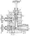
Weitere Vorteile, Merkmale und Einzelheiten der Erfindung ergeben sich aus der nachfolgenden Beschreibung eines Ausführungsbeispiels sowie anhand der Zeichnung, die einen Schnitt durch einen erfindungsgemäßen Ventilblock darstellt.Further advantages, features and details of the invention result from the following description of an exemplary embodiment and from the drawing, which represents a section through a valve block according to the invention.
In einem Grundblock 1 sind dabei ein Anschluß 2 für einen Schlauch zur Einspritzung von Zementschlämme sowie ein Anschluß 3 für einen Druckluftschlauch und schließlich ein weiterer Anschluß 4 für das Schaummittel vorgesehen, während bei 5 ein Anschluß für die abgehende Zementschaumleitung angedeutet ist.In a basic block 1 there is a
Die über eine Druckpumpe angesaugte und mit etwa 28 bar über den Anschluß 2 eingebrachte Zementschlämme wird mit Hilfe eines Einspritzventils 6 mit einem Einstellrad 16 in eine Mischkammer 7 eingespritzt, in welche über ein zweites Einspritzventil 8 mit Einstellrad 9 auch das Schaummittel eingespritzt wird. Am Ende der Mischkammer 7 ist eine quer abgehende Expansionsdüse 10 angeordnet, deren Achse mit der Austrittsachse eines Druckluftventils 11 mit Stellrad 12 fluchtet, um die über den Anschluß 3 eingeleitete Druckluft unmittelbar nach dem Austreten in die Mischkammer 7 mit der Zementschlämme-Schaummittel-Mischung innig zu vermischen, wobei diese Mischung infolge des hohen Drucks unmittelbar in der Expansionsdüse 10 zu einem Zementschaum mit geringem Schaumgewicht aufschäumt, so daß zum Weitertransport dieses fertigen Zementschaums zur Verarbeitungsstelle überhaupt keine weitere Pumpe od. dgl. mehr erforderlich ist. Der hohe Druck von ca. 25 bar in der beispielsweise als 3/4" - Leitung ausgebildeten Schaumleitung, die an den Schaumauslaß 5 angeschlossen werden kann, ermöglicht ein selbsttätiges Weiterfördern dieses Schaums auch in höhere Stockwerke, da das Gewicht des Schaums in einer 10 oder 15 m langen Leitungen immer noch so gering ist, daß der hohe Druck in der Expansionskammer nach wie vor zur selbsttätigen Förderung ausreicht.The cement slurry sucked in via a pressure pump and introduced at about 28 bar via
Die verschiedenen Düsen 6, 8, 11 und 10 sind bevorzugt als auswechselbare Teile 6a, 8a, 11a und 10a in entsprechende Bohrungen des Grundkörpers 1 einschraubbar, so daß ein sehr einfacher Austausch bei etwaigen Beschädigungen oder aufgrund eines Verschleißes im Gebrauch problemlos möglich ist.The
Die Erfindung ist nicht auf das dargestellte Ausführungsbeispiel beschränkt. Neben der bereits eingangs angesprochenen Möglichkeit der Herstellung auch anderer Bauschäume, bei denen anstelle von Zement ein anderes Zuschlagmittel verwendet wird, ließe sich selbstverständlich die Anordnung der Düsen auch in anderer Weise realisieren. Wesentlich ist aber die quasi einstufige Aufschäumung unter Vermeidung des bisherigen zweistufigen Verfahrens, bei dem ein fertiger Schaum erst nachträglich mit dem Zuschlagstoff vermischt wird.The invention is not restricted to the exemplary embodiment shown. In addition to the possibility of producing other construction foams, which were mentioned at the beginning, and in which a different additive is used instead of cement, the arrangement could of course also be used of the nozzles in a different way. What is essential, however, is the quasi one-stage foaming while avoiding the previous two-stage process, in which a finished foam is only subsequently mixed with the additive.
Claims (6)
- Method of manufacturing construction foam from air, water, foaming agent and an additive, in particular cement foam, characterised in that laitance is injected at high pressure into a mixing chamber and is mixed with a foaming agent, and in that the mixture is fed to an expansion nozzle disposed immediately behind, into which compressed air is blown and in which the mixture froths up.
- Method of manufacturing construction foam according to claim 1, characterised in that the laitance is injected at a pressure of 25 bar.
- Method of manufacturing construction foam according to claim 1 or 2, characterised in that the air is injected at approximately 8 bar.
- Apparatus for carrying out the method according to one of claims 1 to 3, characterised by a valve block (1) with connections (2, 3, 4, 5) for the laitance, the foaming agent and compressed air, and an abducting foam line, wherein the discharge axis for the laitance/foaming agent mixutre is transverse to, in particular perpendicular to the expansion nozzle (10) which is disposed immediately behind the injection-mixing nozzle/mixing chamber (6-8) and which is flush with the discharge axis of the compressed air injection nozzle (11).
- Apparatus according to claim 1, characterised in that the injection nozzles (6, 8, 11) for laitance, foaming agent and compressed air are formed as metering valves with externally actuatable setting wheels (16, 9, 12).
- Apparatus according to claim 4 or 5, characterised in that the injection nozzles are disposed exchangeably in a block comprising the connecting bores for the external connections and between various injection nozzles.
Applications Claiming Priority (2)
| Application Number | Priority Date | Filing Date | Title |
|---|---|---|---|
| DE4118537 | 1991-06-06 | ||
| DE4118537A DE4118537C1 (en) | 1991-06-06 | 1991-06-06 |
Publications (2)
| Publication Number | Publication Date |
|---|---|
| EP0517207A1 EP0517207A1 (en) | 1992-12-09 |
| EP0517207B1 true EP0517207B1 (en) | 1995-08-23 |
Family
ID=6433282
Family Applications (1)
| Application Number | Title | Priority Date | Filing Date |
|---|---|---|---|
| EP92109445A Expired - Lifetime EP0517207B1 (en) | 1991-06-06 | 1992-06-04 | Method and device to make construction foam, in particular cement foam |
Country Status (7)
| Country | Link |
|---|---|
| US (1) | US5393341A (en) |
| EP (1) | EP0517207B1 (en) |
| AT (1) | ATE126723T1 (en) |
| DE (2) | DE4118537C1 (en) |
| DK (1) | DK0517207T3 (en) |
| ES (1) | ES2075538T3 (en) |
| GR (1) | GR3017960T3 (en) |
Cited By (2)
| Publication number | Priority date | Publication date | Assignee | Title |
|---|---|---|---|---|
| DE10110917C2 (en) * | 2001-03-07 | 2003-05-15 | Axel Kretzschmar | Method and device for producing a binder foam |
| CN1922120B (en) * | 2004-02-24 | 2010-06-09 | 拉法基石膏公司 | Process and apparatus for manufacturing a set cellular cementitious body |
Families Citing this family (16)
| Publication number | Priority date | Publication date | Assignee | Title |
|---|---|---|---|---|
| DE9209613U1 (en) * | 1992-07-17 | 1992-09-17 | Rume Maschinenbau Gmbh, 8500 Nuernberg, De | |
| DE4408088A1 (en) * | 1994-03-10 | 1995-11-09 | Dennert Kg Veit | Process for the production of a porous, mineral lightweight insulation board |
| DE4443594C2 (en) * | 1994-12-07 | 2000-07-27 | Bayosan Wachter Gmbh & Co Kg | Method for producing a mortar in a spraying device, device for carrying out the method and uses of the mortar |
| DE19537239C2 (en) * | 1995-03-03 | 1997-11-06 | Heidelberger Baustofftech Gmbh | Device and method for producing a foamed binder |
| DE19632666C1 (en) * | 1996-08-14 | 1998-04-23 | Ingenieurkontor Fuer Maschinen | Foam concrete production |
| DE19933245A1 (en) * | 1999-07-15 | 2001-01-18 | Hendrik Vulturius | Method and device for producing foams, in particular foamed porous substances |
| US20030212149A1 (en) * | 2001-08-17 | 2003-11-13 | Grundmann Steven R. | Foaming apparatus and method |
| DE10351690B4 (en) * | 2003-07-04 | 2005-11-17 | F & B GmbH Feuerschutz & Brandbekämpfung | Device for producing a binder foam |
| US7332114B2 (en) | 2005-02-04 | 2008-02-19 | Lafarge Platres | Process for manufacturing sound absorbing cement tile |
| US20080222121A1 (en) * | 2006-06-02 | 2008-09-11 | Wolfgang Wiessler | System for Adaptively Querying a Data Storage Repository |
| FR2953216B1 (en) * | 2009-12-01 | 2012-01-06 | C T D Pulverisation | CEMENT-BASED INSULATING MATERIAL AND METHOD FOR MANUFACTURING THE SAME |
| US10189180B2 (en) * | 2014-01-15 | 2019-01-29 | United States Gypsum Company | Foam injection system with variable port inserts for slurry mixing and dispensing apparatus |
| WO2017143384A1 (en) * | 2016-02-23 | 2017-08-31 | Edgar Donald Knott | A method for the manufacture of foamed plaster |
| AU2016425427B2 (en) | 2016-09-30 | 2021-07-01 | Halliburton Energy Services, Inc. | System and method of producing foamed cement in a laboratory environment |
| CN111888960A (en) * | 2020-07-29 | 2020-11-06 | 中石化四机石油机械有限公司 | Foam generating device for petroleum drilling and production well cementation operation and foaming method thereof |
| AT526383A1 (en) * | 2022-08-08 | 2024-02-15 | Ganzi Gerald | Device for producing foam concrete and conveying the foam concrete to various pouring locations on a construction site |
Family Cites Families (14)
| Publication number | Priority date | Publication date | Assignee | Title |
|---|---|---|---|---|
| CH248162A (en) * | 1943-09-10 | 1947-04-30 | Marchal Louis Amedee | Agitator-mixer for the production of foam and cellular products. |
| DE2545006A1 (en) * | 1975-10-08 | 1977-04-14 | Zellen Leicht Beton Gmbh & Co | Cellular concrete with predetermined bulk density - produced by admixing separately prepd. foam to cement water mixt. |
| FI64569C (en) * | 1977-04-04 | 1983-12-12 | Dyno Industrier As | FOERFARANDE FOER KONTINUERLIG FRAMSTAELLNING AV ETT SPRAENGAEMNE GENOM ATT SAMMANBLANDA MINST TVAO FLYTANDE COMPONENTS OC ANORDNING FOER UTFOERANDE AV FOERFARANDET |
| GB2086748B (en) * | 1980-10-11 | 1985-07-31 | Domocon Sa | Aerated concrete |
| DE3039510A1 (en) * | 1980-10-20 | 1982-06-03 | Hoechst Ag, 6000 Frankfurt | DEVICE AND METHOD FOR DISPERSING AND SOLVING POLYMER POWDERS |
| FR2503617A1 (en) * | 1981-04-10 | 1982-10-15 | Dion Biro Guy | Cellular mortar made by mixing cement and water into thick paste - and then adding foam obtd. by injecting compressed air into water contg. emulsifier |
| DE3132667A1 (en) * | 1981-08-14 | 1983-02-24 | Lehmann & Co GmbH, 2120 Lüneburg | Process and device for producing porous concrete or foam concrete or the like |
| US4470727A (en) * | 1982-04-15 | 1984-09-11 | The Dow Chemical Company | Apparatus and process for foamed cementing |
| DE3222033A1 (en) * | 1982-06-11 | 1983-12-15 | KBI Klöckner-Becorit Industrietechnik GmbH, 4224 Hünxe | Process and device for producing porous mortar |
| JPS6186472A (en) * | 1984-10-04 | 1986-05-01 | 日本シポレツクス工業株式会社 | Lightweight foamed concrete |
| JPS61239916A (en) * | 1985-04-16 | 1986-10-25 | Mitsubishi Plastics Ind Ltd | Expansion injection molding method |
| ZA881468B (en) * | 1987-03-06 | 1988-08-23 | Anthes Industries Inc. | Method and apparatus for the production of cellular concrete and foam concentrate used therein |
| GB2217221B (en) * | 1988-04-20 | 1991-12-11 | Gary Kenneth Busch | Apparatus for preparing foamed concrete or other foamed products |
| US5098267A (en) * | 1990-06-22 | 1992-03-24 | Union Carbide Industrial Gases Technology Corporation | Apparatus and method for producing and molding structural foam |
-
1991
- 1991-06-06 DE DE4118537A patent/DE4118537C1/de not_active Expired - Fee Related
-
1992
- 1992-06-04 DE DE59203343T patent/DE59203343D1/en not_active Expired - Fee Related
- 1992-06-04 EP EP92109445A patent/EP0517207B1/en not_active Expired - Lifetime
- 1992-06-04 AT AT92109445T patent/ATE126723T1/en not_active IP Right Cessation
- 1992-06-04 DK DK92109445.4T patent/DK0517207T3/en active
- 1992-06-04 ES ES92109445T patent/ES2075538T3/en not_active Expired - Lifetime
-
1993
- 1993-12-23 US US08/173,262 patent/US5393341A/en not_active Expired - Fee Related
-
1995
- 1995-11-01 GR GR950403071T patent/GR3017960T3/en unknown
Cited By (2)
| Publication number | Priority date | Publication date | Assignee | Title |
|---|---|---|---|---|
| DE10110917C2 (en) * | 2001-03-07 | 2003-05-15 | Axel Kretzschmar | Method and device for producing a binder foam |
| CN1922120B (en) * | 2004-02-24 | 2010-06-09 | 拉法基石膏公司 | Process and apparatus for manufacturing a set cellular cementitious body |
Also Published As
| Publication number | Publication date |
|---|---|
| ATE126723T1 (en) | 1995-09-15 |
| GR3017960T3 (en) | 1996-02-29 |
| DK0517207T3 (en) | 1995-11-27 |
| ES2075538T3 (en) | 1995-10-01 |
| DE59203343D1 (en) | 1995-09-28 |
| US5393341A (en) | 1995-02-28 |
| EP0517207A1 (en) | 1992-12-09 |
| DE4118537C1 (en) | 1992-07-30 |
Similar Documents
| Publication | Publication Date | Title |
|---|---|---|
| EP0517207B1 (en) | Method and device to make construction foam, in particular cement foam | |
| DE2634494C2 (en) | New injectors for liquid gassing | |
| DE2231141A1 (en) | DEVICE FOR GENERATING CLEANING FOAM | |
| EP0078960B1 (en) | Method and device for glueing particles, especially wood-shavings | |
| DE3515967A1 (en) | VIBRATION METHOD FOR CLEARING A CLOGGED SUSPENSION PIPELINE | |
| EP1663533A1 (en) | Method of the generation of a cleaning agent foam and injector and foam generation system for carrying out said method | |
| CH662070A5 (en) | Process and device for flushing and cleaning a pipeline | |
| EP0142595B1 (en) | Method and apparatus for the treatment of pouring water during the pouring by enrichment with co2 and h2co3 | |
| WO2016120046A2 (en) | Device and method for the gluing of particles | |
| WO2008116530A1 (en) | Device for the continuous mixing of gases in water | |
| DE10020162C2 (en) | Method and device for producing a flowable reaction mixture that forms a solid or foam | |
| DE10351690B4 (en) | Device for producing a binder foam | |
| DE3233744A1 (en) | Process for mixing a dry mix and water during dry spraying, and mixing tube for the dry-spraying process | |
| EP2931840B1 (en) | Method and system for producing a binder foam for producing asphalt | |
| DE3712151C2 (en) | ||
| DE3220880C2 (en) | Method for mixing dry concrete mix and water during dry concrete spraying and mixing tube for dry concrete spraying | |
| EP0578968B1 (en) | Method for the production of construction foam and foaming apparatus for carrying out the method | |
| DE3809473A1 (en) | Cleaning apparatus in installations for the synthesis of chemical compounds, installation containing the cleaning apparatus and process for cleaning the installation | |
| DD138056B1 (en) | DEVICE FOR PNEUMATIC TRANSPORT, ESPECIALLY FOR HEAVY-DUTY, STRONG-SLIPPING OR EXPLOSIVE SHOE-LOADERS | |
| DE3429010C2 (en) | ||
| EP0554692A1 (en) | Method for sand-blasting and device for carrying out the method | |
| EP1685893A1 (en) | Apparatus for enriching liquids with gas | |
| EP1500413A1 (en) | Fire extinguishing device | |
| CH684055A5 (en) | Launcher tube with a mixing device for producing a liquid mixture jet. | |
| DE3318140A1 (en) | Compressed air cleaning device |
Legal Events
| Date | Code | Title | Description |
|---|---|---|---|
| PUAI | Public reference made under article 153(3) epc to a published international application that has entered the european phase |
Free format text: ORIGINAL CODE: 0009012 |
|
| AK | Designated contracting states |
Kind code of ref document: A1 Designated state(s): AT BE CH DE DK ES FR GB GR IT LI LU MC NL PT SE |
|
| 17P | Request for examination filed |
Effective date: 19930514 |
|
| 17Q | First examination report despatched |
Effective date: 19940808 |
|
| GRAA | (expected) grant |
Free format text: ORIGINAL CODE: 0009210 |
|
| AK | Designated contracting states |
Kind code of ref document: B1 Designated state(s): AT BE CH DE DK ES FR GB GR IT LI LU MC NL PT SE |
|
| REF | Corresponds to: |
Ref document number: 126723 Country of ref document: AT Date of ref document: 19950915 Kind code of ref document: T |
|
| REF | Corresponds to: |
Ref document number: 59203343 Country of ref document: DE Date of ref document: 19950928 |
|
| ET | Fr: translation filed | ||
| REG | Reference to a national code |
Ref country code: ES Ref legal event code: FG2A Ref document number: 2075538 Country of ref document: ES Kind code of ref document: T3 |
|
| ITF | It: translation for a ep patent filed |
Owner name: ING. C. GREGORJ S.P.A. |
|
| REG | Reference to a national code |
Ref country code: DK Ref legal event code: T3 |
|
| GBT | Gb: translation of ep patent filed (gb section 77(6)(a)/1977) |
Effective date: 19951107 |
|
| REG | Reference to a national code |
Ref country code: GR Ref legal event code: FG4A Free format text: 3017960 |
|
| PGFP | Annual fee paid to national office [announced via postgrant information from national office to epo] |
Ref country code: PT Payment date: 19960516 Year of fee payment: 5 |
|
| PGFP | Annual fee paid to national office [announced via postgrant information from national office to epo] |
Ref country code: GR Payment date: 19960520 Year of fee payment: 5 |
|
| PGFP | Annual fee paid to national office [announced via postgrant information from national office to epo] |
Ref country code: DK Payment date: 19960627 Year of fee payment: 5 |
|
| PLBE | No opposition filed within time limit |
Free format text: ORIGINAL CODE: 0009261 |
|
| STAA | Information on the status of an ep patent application or granted ep patent |
Free format text: STATUS: NO OPPOSITION FILED WITHIN TIME LIMIT |
|
| PGFP | Annual fee paid to national office [announced via postgrant information from national office to epo] |
Ref country code: MC Payment date: 19960701 Year of fee payment: 5 |
|
| 26N | No opposition filed | ||
| PG25 | Lapsed in a contracting state [announced via postgrant information from national office to epo] |
Ref country code: DK Free format text: LAPSE BECAUSE OF NON-PAYMENT OF DUE FEES Effective date: 19970604 |
|
| REG | Reference to a national code |
Ref country code: DK Ref legal event code: EBP |
|
| PG25 | Lapsed in a contracting state [announced via postgrant information from national office to epo] |
Ref country code: GR Free format text: LAPSE BECAUSE OF NON-PAYMENT OF DUE FEES Effective date: 19970630 |
|
| PGFP | Annual fee paid to national office [announced via postgrant information from national office to epo] |
Ref country code: LU Payment date: 19970814 Year of fee payment: 6 |
|
| REG | Reference to a national code |
Ref country code: CH Ref legal event code: PUE Owner name: RUME MASCHINENBAU GMBH TRANSFER- ZTI ZEMENTSCHAUM- |
|
| PG25 | Lapsed in a contracting state [announced via postgrant information from national office to epo] |
Ref country code: PT Effective date: 19971231 Ref country code: MC Effective date: 19971231 |
|
| REG | Reference to a national code |
Ref country code: FR Ref legal event code: TP |
|
| NLS | Nl: assignments of ep-patents |
Owner name: ZTI ZEMENTSCHAUM-TECHNIK INTERNATIONAL GMBH |
|
| REG | Reference to a national code |
Ref country code: ES Ref legal event code: PC2A |
|
| REG | Reference to a national code |
Ref country code: GB Ref legal event code: 732E |
|
| REG | Reference to a national code |
Ref country code: PT Ref legal event code: MM4A Free format text: LAPSE DUE TO NON-PAYMENT OF FEES Effective date: 19971231 |
|
| PGFP | Annual fee paid to national office [announced via postgrant information from national office to epo] |
Ref country code: GB Payment date: 19980529 Year of fee payment: 7 |
|
| PG25 | Lapsed in a contracting state [announced via postgrant information from national office to epo] |
Ref country code: LU Free format text: LAPSE BECAUSE OF NON-PAYMENT OF DUE FEES Effective date: 19980604 |
|
| PG25 | Lapsed in a contracting state [announced via postgrant information from national office to epo] |
Ref country code: GB Free format text: LAPSE BECAUSE OF NON-PAYMENT OF DUE FEES Effective date: 19990604 |
|
| PGFP | Annual fee paid to national office [announced via postgrant information from national office to epo] |
Ref country code: CH Payment date: 19991220 Year of fee payment: 8 Ref country code: AT Payment date: 19991220 Year of fee payment: 8 |
|
| PGFP | Annual fee paid to national office [announced via postgrant information from national office to epo] |
Ref country code: SE Payment date: 19991221 Year of fee payment: 8 |
|
| PGFP | Annual fee paid to national office [announced via postgrant information from national office to epo] |
Ref country code: FR Payment date: 19991223 Year of fee payment: 8 |
|
| PGFP | Annual fee paid to national office [announced via postgrant information from national office to epo] |
Ref country code: NL Payment date: 19991229 Year of fee payment: 8 Ref country code: ES Payment date: 19991229 Year of fee payment: 8 |
|
| PGFP | Annual fee paid to national office [announced via postgrant information from national office to epo] |
Ref country code: DE Payment date: 19991230 Year of fee payment: 8 |
|
| PGFP | Annual fee paid to national office [announced via postgrant information from national office to epo] |
Ref country code: BE Payment date: 20000105 Year of fee payment: 8 |
|
| GBPC | Gb: european patent ceased through non-payment of renewal fee |
Effective date: 19990604 |
|
| PG25 | Lapsed in a contracting state [announced via postgrant information from national office to epo] |
Ref country code: AT Free format text: LAPSE BECAUSE OF NON-PAYMENT OF DUE FEES Effective date: 20000604 |
|
| PG25 | Lapsed in a contracting state [announced via postgrant information from national office to epo] |
Ref country code: SE Free format text: LAPSE BECAUSE OF NON-PAYMENT OF DUE FEES Effective date: 20000605 Ref country code: ES Free format text: THE PATENT HAS BEEN ANNULLED BY A DECISION OF A NATIONAL AUTHORITY Effective date: 20000605 |
|
| PG25 | Lapsed in a contracting state [announced via postgrant information from national office to epo] |
Ref country code: LI Free format text: LAPSE BECAUSE OF NON-PAYMENT OF DUE FEES Effective date: 20000630 Ref country code: CH Free format text: LAPSE BECAUSE OF NON-PAYMENT OF DUE FEES Effective date: 20000630 Ref country code: BE Free format text: LAPSE BECAUSE OF NON-PAYMENT OF DUE FEES Effective date: 20000630 |
|
| BERE | Be: lapsed |
Owner name: ZEMENTSCHAUM-TECHNIK INTERNTIONAL G.M.B.H. ZTI Effective date: 20000630 |
|
| PG25 | Lapsed in a contracting state [announced via postgrant information from national office to epo] |
Ref country code: NL Free format text: LAPSE BECAUSE OF NON-PAYMENT OF DUE FEES Effective date: 20010101 |
|
| REG | Reference to a national code |
Ref country code: CH Ref legal event code: PL |
|
| EUG | Se: european patent has lapsed |
Ref document number: 92109445.4 |
|
| PG25 | Lapsed in a contracting state [announced via postgrant information from national office to epo] |
Ref country code: FR Free format text: LAPSE BECAUSE OF NON-PAYMENT OF DUE FEES Effective date: 20010228 |
|
| NLV4 | Nl: lapsed or anulled due to non-payment of the annual fee |
Effective date: 20010101 |
|
| REG | Reference to a national code |
Ref country code: FR Ref legal event code: ST |
|
| PG25 | Lapsed in a contracting state [announced via postgrant information from national office to epo] |
Ref country code: DE Free format text: LAPSE BECAUSE OF NON-PAYMENT OF DUE FEES Effective date: 20010403 |
|
| REG | Reference to a national code |
Ref country code: ES Ref legal event code: FD2A Effective date: 20020204 |
|
| PG25 | Lapsed in a contracting state [announced via postgrant information from national office to epo] |
Ref country code: IT Free format text: LAPSE BECAUSE OF NON-PAYMENT OF DUE FEES;WARNING: LAPSES OF ITALIAN PATENTS WITH EFFECTIVE DATE BEFORE 2007 MAY HAVE OCCURRED AT ANY TIME BEFORE 2007. THE CORRECT EFFECTIVE DATE MAY BE DIFFERENT FROM THE ONE RECORDED. Effective date: 20050604 |