EP0515835A2 - Apparatus and method for disposing wasted cans - Google Patents
Apparatus and method for disposing wasted cans Download PDFInfo
- Publication number
- EP0515835A2 EP0515835A2 EP92106930A EP92106930A EP0515835A2 EP 0515835 A2 EP0515835 A2 EP 0515835A2 EP 92106930 A EP92106930 A EP 92106930A EP 92106930 A EP92106930 A EP 92106930A EP 0515835 A2 EP0515835 A2 EP 0515835A2
- Authority
- EP
- European Patent Office
- Prior art keywords
- press
- support plate
- portions
- lower ends
- supporting portion
- Prior art date
- Legal status (The legal status is an assumption and is not a legal conclusion. Google has not performed a legal analysis and makes no representation as to the accuracy of the status listed.)
- Withdrawn
Links
Images


Classifications
-
- B—PERFORMING OPERATIONS; TRANSPORTING
- B30—PRESSES
- B30B—PRESSES IN GENERAL
- B30B9/00—Presses specially adapted for particular purposes
- B30B9/32—Presses specially adapted for particular purposes for consolidating scrap metal or for compacting used cars
- B30B9/321—Presses specially adapted for particular purposes for consolidating scrap metal or for compacting used cars for consolidating empty containers, e.g. cans
Definitions
- the present invention relates to an apparatus and a method for disposing empty wasted cans such as beer cans, fruit juice cans or the like by pressing these cans.
- the present inventor has proposed, in the specification of Japanese Patent Application No. 2-283657, a wasted can disposal apparatus which presses, between a movable press member and a stationary press member, wasted and which are received by a bottom plate.
- Figs. 11 to 14 of Japanese Patent Application No. 2-283657 cans 4' put into the space between a stationary press member and a movable press member are received by a bottom plate 50' which is set at a level below the lower ends of both press members. and are pressed between these press members as the movable press member is moved towards the stationary press member, as shown in Figs. 13 to 16 attached hereto.
- numeral 5' denotes a motor
- 26' denotes a press member
- 29' denotes a transmission member
- 30' denotes an elastic member
- 50a' denotes a bent portion
- 51' denotes a motor
- 52' denotes a shaft.
- the can 4' when pressed by the apparatus, is deformed not only in the direction of compression but also in the vertical direction perpendicular to the direction of pressing, so as to push the bottom plate 50' downward, thus swelling out downward beyond the lower ends of the pressing members.
- the portion of the can swelled out from the region between both pressing members is no more pressed, so that a non-pressed portion undesirably remains in the can after the press work.
- an object of the present invention is to overcome the above-described problems of the prior art.
- the present invention provides a can disposal apparatus and method in which a support plate for receiving and supporting cans is initially set at a level above the lower ends of first and second press members and is moved to down to a level below the lower ends of the press members at least during the pressing.
- the wasted cans put into the gap between both press members are supported by the support plate and, when the pressing is commenced, the support plate is retracted to the level below the lower ends of the press members. Consequently, any vertically swelled portion of each can is still within the region between the first and second press members so that the amount of swelling of the can out of the pressing region is reduced or substantially eliminated.
- the support plate undesirably tends to move into a space behind the moving press portion, due to the arrangement that the supporting portion of the support member is positioned above the level of the lower ends of the first and second press portions. This, however, does not take place actually because, in the present invention, the side tabs of the support plate engage with the guide portions in accordance with the operation of the advancing/retracting means, so as to downward rotate the support plate to a level below the level of the lower ends of the first and second press portions.
- a can disposal apparatus as an embodiment of the present invention is generally denoted by 1.
- the apparatus 1 has a first press portion 2 and a second press portion 3 between which a can 4 to be disposed is placed.
- the second press portion i drivingly connected to a motor 5 through a mechanism for converting a rotational motion into a linear reciprocating motion, so that the second press portion 3 is moved towards the first press portion 2 so as to press the can 4 therebetween.
- the apparatus has a guide section A which decides whether the can 4 put into the apparatus is to be guided to a pressing chamber or to a non-pressing chamber, and a press section B for pressing the can 4 which has been introduced into the pressing chamber.
- the guide portion A includes a door 7 rotatable about a pivot shaft 6, a stopper portion 8 which decides whether the weight of the can 4 put into the apparatus is grater than a predetermined weight, a releasing portion for releasing the stopper portion, and a guide 10 for selectively guiding the can 4 either to a passage B1 leading to the pressing chamber and a passage B2 leading to the non-pressing chamber.
- a sensor 11 disposed in the vicinity of the door 7 is capable of sensing the state of the door 7, and delivers a signal to a controller 12 when the door has been moved from the open position to the close position.
- the stopper portion 8 includes a lever 81 having an L-shaped sectional shape, pivotally supported by a pivot shaft 13.
- a spring 14 is retained at its one end by the lever 81 and at its other end by a protruding portion provided on an activating member 20.
- the arrangement is such that, when the weight of the can 4 exceeds a predetermined value, the spring 14 is compressed to allow the stopper portion 8 to rotate counterclockwise, so that the lever 81 interrupts the passage of light from a photoelectric tube 15.
- a signal is delivered to the controller 12 when the light is interrupted.
- the releasing portion 9 is for releasing the can 4 from the stopper.
- the releasing portion 9 includes a first solenoid 16 cooperating with a first plunger 17 to which is secured a first arm 18.
- the aforesaid first activating member 20 is pivotally connected to the other end of the first arm 18.
- the guide 10 is adapted for selectively guiding the can 4 either to the aforementioned passage B1 leading to the pressing chamber and the aforementioned passage B2 leading to the non-pressing chamber.
- the guide 10 includes a second solenoid 21 cooperating with a second plunger 22 to which is secured a second arm 23.
- a guide member 25 is pivotally connected to the other end of the second arm 23 by means of a pivot shaft 24.
- both the first and second solenoids 16 and 21 are shown in de-energized state, i.e., OFF state.
- the pressing section B which is composed of the first and second press portions 2,3 and the support plate 70, clamp the can 4 which has been put into the gap between both press portions 2 and 3 through the guide 10 held in open state.
- the rotation output of the motor is converted into linear motion of the second press portion 3 so that the second press portion 3 is moved towards the first press portion 2 so as to pres the can 4 and then moved away from the first press portion 2.
- the mechanism for converting the rotary motion of the motor shaft into linear reciprocating motion includes, as shown in Fig. 12, a roller 52' which is pressed into a channel 32' formed between a pair of transmission members 29' and 29''.
- the apparatus also includes a first connecting rod 82 contacting a cam 81, a second connecting rod 83 connected to the first connecting rod 82, a third connecting rod 84 connected to the second connecting rod 83, and a fourth connecting rod 87 connected to the support plate 70 and having a projection 86 engaging with an elongated hole in the third connecting rod 84.
- These connecting rods are omitted from Fig. 12.
- An expandable elastic member 30 enables the transmission members 29', 29'' to move as a unit together with the second press portion 3, when the force acting on the pressing surface of the second press portion 3 is below a predetermined level, e.g., 250 kg.
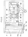
- the support plate 70 is placed at the lower end portion of the press apparatus so as to receive the can 4 which has been put into the gap between both press portions 2 and 3 as shown in Fig. 3.
- the support plate 70 is adapted to be retracted at least during discharging of the pressed can, so that the pressed can drops into a collecting box 53.
- a sorting guide 55 is adapted for sorting the pressed cans according to the materials of the can, so that iron or steel cans are introduced into the collecting box 53, while aluminum cans are introduced into another collecting box which is not shown.
- the support plate 70 has two portions which are hinged to each other through a hinge 71 and are urged by a resilient member such as a spring 72.
- the bottom portion of the support plate 70 has slits 73 which divide the bottom portion into a central supporting portion 70a for supporting the can and the remainder wing portions 70b.
- the supporting portion 70a has been slightly bent upward so as to be positioned above the level of the wing portions 70b. Lateral ends of both wing portion 70b are bent upward to provide side tabs 74.
- the support plate 70 is divided into a stationary part and a movable part which are hinged together through the hinge 71 urged by the resilient member 72, and the movable part has sits 73 which define the central supporting portion 70a and the remainder both wing portions 70b, the supporting portion 70a being slightly bent upward so as to be positioned at a level slightly above the level of the remainder portions 70b.
- the support plate 70 is associated with a advancing/retracting means 80 which is adapted to advance and retract the support plate 70.
- the advancing/retracting means 80 includes, for example, a cam 81 driven by the motor 5, the first connecting rod 82 contacting the cam 81, the second connecting rod 83 connected to the first connecting rod 82, the third connecting rod 84 connected to the second connecting rod 83, and the fourth connecting rod 87 connected to the support plate 70 and having the projection 86 engaging with the elongated hole 85 in the third connecting rod 84, all of which are mentioned before.
- the first connecting rod 82 is urged by a spring 88 so as to be held in contact with the cam 81, and the fourth connecting rod 87 is connected to the support plate 70.
- a spring 88 is used for urging the end of the first connecting rod 82 into contact with the cam 81, such a spring 88 may be substituted by a spring 88' which is provided on an attaching plate 87' integrally secured to the fourth connecting rod 87 as shown in Figs. 10 and 11.
- Numeral 89 denotes a guide of the fourth connecting rod 87 provided on a bottom plate 89'.
- a guide portion 90 provided at lateral sides of the pressing chamber C are adapted to contact with the side tabs 74 of the support plate 70 in accordance with the operation of the advancing/retracting means 80, so as to swing the support plate 74 downward away from the bottom ends of the first and second press portions 2 and 3 against the force of the spring 72.
- the supporting portion 70a of the support plate 70 is held at a level above the lower ends of the first and second press portions 2, 3, so as to support the can 4. The pressing operation is commenced in this state.
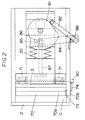
- the distance between the first and second press portions 2 and 3 is maximized as shown in Fig. 2, and the end of the first connecting rod 82 is held in contact with the valley portion of the cam 81, while the support plate 70 has been fully advanced.
- the cam 81 rotates in the direction of an arrow shown in Fig. 2, so that the second press portion 3 is moved towards the first press portion 2 thereby pressing the can 4 therebetween.
- the pressed can is swelled downward so as to push downward the supporting portion 70a of the support plate 70, so that the supporting portion 70a is lowered to a level below the lower ends of both press portions 2 and 3.
- the support plate 70 is removed from the region under the lower ends of the first and second press portions 2 and 3.
- the second press portion 3 is moved towards the first press portion 2, while the end of the connecting rod 82 is moved from the valley to the crest portion of the cam 81, whereby the support plate 70 starts to move backward, as shown in Figs. 4 and 5.
- the support plate 70 is reset so as to position the supporting portion 70a at a level above the level of the lower ends of the first and second press portions 2 and 3, thus preparing for the receipt of the next can.
- the support pate 70 is prevented from entering the space behind the moving press member which is, in this case, the second press portion 3.
- the retraction of the support plate 70 is commenced immediately after the start of the pressing.
- This is only illustrative and the arrangement may be such that the retraction of the support plate is commenced when the pressing is being performed. It is even possible to retract the support plate 70 after the completion of the pressing.
- Such change of the timing of commencement of the retraction can be freely set by altering the rotational phase or contour of the cam 81.
- the support plate 70 has been removed from the region beneath the lower ends of the first and second press portions 2, 3 so as not to hamper the discharge of the pressed can.
- one form of the can disposal method of the invention for disposing a wasted can comprises: a first step of placing the wasted can into a gap formed between a first press portion and a second press portion such that the can is supported by a supporting portion of a support plate, the supporting portion being positioned at a level above the level of the lower ends of the first and second press portions; a second step for commencing a relative movement between the first and second press portions toward each other so as to start pressing the can, while moving the supporting portion of the support plate to a region below the lower ends of the first and second press portions; a third step for further continuing the relative movement between the first and second press portions so as to further press the can, and then removing the support plate from the region under the lower ends of the first and second press portions during the pressing of the can; a fourth step for causing a relative movement between the first and second press members away from each other so as to release and discharge the pressed can; and resetting the support plate such that the supporting portion is positioned between the mutually spaced apart first and second
- Another form of the method for disposing a wasted can comprises: a first step of placing the wasted can into a gap formed between a first press portion and a second press portion such that the can is supported by a supporting portion of a support plate, the supporting portion being positioned at a level above the level of the lower ends of the first and second press portions; a second step for commencing a relative movement between the first and second press portions toward each other so as to start pressing the can, while moving the supporting portion of the support plate to a region below the lower ends of the first and second press portions; a third step for further continuing the relative movement between the first and second press portions so as to further press the can; a fourth step for removing the support plate from the region under the lower ends of the first and second press portions during the pressing of the can, and causing a relative movement between the first and second press members away from each other so as to release and discharge the pressed can; and resetting the support plate such that the supporting portion is positioned between the mutually spaced apart first and second press portions at a level above the
- both the second press portion 3 and the cam 81 are activated by the same motor 5, without requiring any sensor or the like for the purpose of control. Consequently, the control system is simplified and the operation speed can be increased.
- the present invention offers the following advantages.
- the supporting portion of the support plate for supporting the can is positioned at a level above the lower ends of the first and second press portions when the pressing stroke is commenced, the lower end of the can is still held within the region between both press portions, despite any downward swelling of the can occurring during the pressing, so that swelling of the can material out of the lower ends of the press portions can be minimized, thus reducing non-pressed portion of the can which tends to appear in the conventional can disposal apparatus.
- the support plate undesirably tends to move into a space behind the moving press portion, due to the arrangement that the supporting portion of the support member is positioned above the level of the lower ends of the first and second press portions. This, however, does not take place actually because, in the present invention, the side tabs of the support plate engage with the guide portions in accordance with the operation of the advancing/retracting means, so as to downward rotate the support plate to a level below the level of the lower ends of the first and second press portions.
- the spring associated with the second press portion which normally moves together with the second press portion without contracting, is compressed when a load exceeding a predetermined level, so as to protect the driving system for driving the moving side of the apparatus, in particular the driving motor, against any overload.
- the method of the present invention has the first step in which the can put into the space between the first and second press portions is supported by the supporting portion of the support plate, the supporting portion being set at a level above the lower ends of the first and second press portions, and the fourth step in which the support plate is retracted from the region beneath the lower ends of the first and second press portions at least when the pressed can is discharged. It is therefore possible to minimize any non-pressed portion of the can which tends to remain after the pressing operation.
Landscapes
- Engineering & Computer Science (AREA)
- Mechanical Engineering (AREA)
- Refuse Collection And Transfer (AREA)
- Processing Of Solid Wastes (AREA)
Abstract
A can disposal apparatus and method for disposing a wasted can, wherein the can is put into the gap between first and second press portions which are relatively movable toward and away from each other, and is supported by a supporting portion of a support plate which is positioned between both press portions at a level above the lower ends of both press portions. The pressing is effected by the relative movement between both press portions. Since the can is supported by the supporting portion of the support pate positioned above the lower ends of both press portions, the can is pressed without substantially leaving non-pressed portion. The support plate is suitably retracted during the pressing. In one form of the invention, the support plate is swung downward away from the lower ends of the pres portions so that the support plate does never move into a space behind the moving press portion. In another form, a spring is provided on the moving pres portion so as to move together with this pres portion. When an abnormally heavy load is applied to the press portion, the spring is compressed to absorb the load, thereby protecting the driving system for driving the moving press portion.
Description
- The present invention relates to an apparatus and a method for disposing empty wasted cans such as beer cans, fruit juice cans or the like by pressing these cans.
- The present inventor has proposed, in the specification of Japanese Patent Application No. 2-283657, a wasted can disposal apparatus which presses, between a movable press member and a stationary press member, wasted and which are received by a bottom plate.
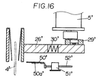
- Referring to Figs. 11 to 14 of Japanese Patent Application No. 2-283657, cans 4' put into the space between a stationary press member and a movable press member are received by a bottom plate 50' which is set at a level below the lower ends of both press members. and are pressed between these press members as the movable press member is moved towards the stationary press member, as shown in Figs. 13 to 16 attached hereto. For information, in Figs. 13 to 16, numeral 5' denotes a motor, 26' denotes a press member, 29' denotes a transmission member, 30' denotes an elastic member, 50a' denotes a bent portion, 51' denotes a motor, and 52' denotes a shaft.
- The can 4', when pressed by the apparatus, is deformed not only in the direction of compression but also in the vertical direction perpendicular to the direction of pressing, so as to push the bottom plate 50' downward, thus swelling out downward beyond the lower ends of the pressing members. The portion of the can swelled out from the region between both pressing members is no more pressed, so that a non-pressed portion undesirably remains in the can after the press work.
- Accordingly, an object of the present invention is to overcome the above-described problems of the prior art.
- To this end, the present invention provides a can disposal apparatus and method in which a support plate for receiving and supporting cans is initially set at a level above the lower ends of first and second press members and is moved to down to a level below the lower ends of the press members at least during the pressing.
- Thus, according to the invention, the wasted cans put into the gap between both press members are supported by the support plate and, when the pressing is commenced, the support plate is retracted to the level below the lower ends of the press members. Consequently, any vertically swelled portion of each can is still within the region between the first and second press members so that the amount of swelling of the can out of the pressing region is reduced or substantially eliminated.
- It may appear that the support plate undesirably tends to move into a space behind the moving press portion, due to the arrangement that the supporting portion of the support member is positioned above the level of the lower ends of the first and second press portions. This, however, does not take place actually because, in the present invention, the side tabs of the support plate engage with the guide portions in accordance with the operation of the advancing/retracting means, so as to downward rotate the support plate to a level below the level of the lower ends of the first and second press portions.
-
- Fig. 1 is a schematic sectional side elevational view of a can disposal apparatus as an embodiment of the present invention;
- Fig. 2 is a schematic plan view of a critical portion of the apparatus shown in Fig. 1, in a state ready for receiving cans;
- Fig. 3 is a schematic sectional side elevational view of a critical portion of the apparatus shown in Fig. 1, in a state immediately before commencement of pressing operation;
- Fig. 4 is a schematic plan view of a critical portion of the apparatus shown in Fig. 1, in a state after completion of the pressing operation;
- Fig. 5 is a schematic sectional side elevational view of the apparatus in the state shown in Fig. 4;
- Fig. 6 is a schematic plan view of a critical portion of the apparatus, in a state for discharging pressed cans;
- Fig. 7 is a schematic sectional side elevational view of a critical portion of the apparatus, in the state for discharging pressed cans;
- Fig. 8 is a schematic perspective view of a portion of the apparatus, illustrative of the state of contact between a guide portion and a side portion;
- Fig. 9 is a schematic perspective view of a portion of the apparatus, illustrative of the state of contact between the guide portion and the side portion, with a portion of the support plate having been swung;
- Fig. 10 is an illustration of a can disposal apparatus as a second embodiment of the present invention, in a state ready for receiving cans to be pressed;
- Fig. 11 is a schematic sectional side elevational view of the apparatus shown in Fig. 1 in a state before commencement of pressing operation;
- Fig. 12 is a schematic perspective view of the apparatus of Fig. 1, as viewed from the driving side thereof; and
- Figs. 13 to 16 are illustrations of a known can disposal apparatus of the type which is disclosed in Japanese Patent Application No. 2-283657, illustrating states in which a can is being compressed between a stationary press member and a movable press member.
- Referring to the drawings, a can disposal apparatus as an embodiment of the present invention is generally denoted by 1. The apparatus 1 has a
first press portion 2 and asecond press portion 3 between which a can 4 to be disposed is placed. The second press portion i drivingly connected to amotor 5 through a mechanism for converting a rotational motion into a linear reciprocating motion, so that thesecond press portion 3 is moved towards thefirst press portion 2 so as to press thecan 4 therebetween. - More specifically, the apparatus has a guide section A which decides whether the can 4 put into the apparatus is to be guided to a pressing chamber or to a non-pressing chamber, and a press section B for pressing the
can 4 which has been introduced into the pressing chamber. - The guide portion A includes a
door 7 rotatable about a pivot shaft 6, a stopper portion 8 which decides whether the weight of the can 4 put into the apparatus is grater than a predetermined weight, a releasing portion for releasing the stopper portion, and aguide 10 for selectively guiding thecan 4 either to a passage B1 leading to the pressing chamber and a passage B2 leading to the non-pressing chamber. - A sensor 11 disposed in the vicinity of the
door 7 is capable of sensing the state of thedoor 7, and delivers a signal to acontroller 12 when the door has been moved from the open position to the close position. - The stopper portion 8 includes a
lever 81 having an L-shaped sectional shape, pivotally supported by apivot shaft 13. - A
spring 14 is retained at its one end by thelever 81 and at its other end by a protruding portion provided on an activatingmember 20. - The arrangement is such that, when the weight of the
can 4 exceeds a predetermined value, thespring 14 is compressed to allow the stopper portion 8 to rotate counterclockwise, so that thelever 81 interrupts the passage of light from aphotoelectric tube 15. - A signal is delivered to the
controller 12 when the light is interrupted. - The releasing portion 9 is for releasing the
can 4 from the stopper. The releasing portion 9 includes a first solenoid 16 cooperating with afirst plunger 17 to which is secured afirst arm 18. The aforesaid first activatingmember 20 is pivotally connected to the other end of thefirst arm 18. - Thus, the releasing portion 9 and the stopper portion 8 are connected together through the
spring 14. - The
guide 10 is adapted for selectively guiding thecan 4 either to the aforementioned passage B1 leading to the pressing chamber and the aforementioned passage B2 leading to the non-pressing chamber. Theguide 10 includes asecond solenoid 21 cooperating with asecond plunger 22 to which is secured asecond arm 23. Aguide member 25 is pivotally connected to the other end of thesecond arm 23 by means of apivot shaft 24. - In Fig. 1, both the first and
second solenoids 16 and 21 are shown in de-energized state, i.e., OFF state. - As will be seen from Figs. 2 to 7, the pressing section B, which is composed of the first and
second press portions support plate 70, clamp thecan 4 which has been put into the gap between bothpress portions guide 10 held in open state. As themotor 5 operates, the rotation output of the motor is converted into linear motion of thesecond press portion 3 so that thesecond press portion 3 is moved towards thefirst press portion 2 so as to pres thecan 4 and then moved away from thefirst press portion 2. The mechanism for converting the rotary motion of the motor shaft into linear reciprocating motion includes, as shown in Fig. 12, a roller 52' which is pressed into a channel 32' formed between a pair of transmission members 29' and 29''. Lateral displacement of the roller 52' is converted into linear reciprocating motion of thesecond press portion 3, thereby moving thesecond press portion 3 towards and away from thefirst press portion 2. The apparatus also includes a first connectingrod 82 contacting acam 81, a second connectingrod 83 connected to the first connectingrod 82, a third connectingrod 84 connected to the second connectingrod 83, and a fourth connectingrod 87 connected to thesupport plate 70 and having aprojection 86 engaging with an elongated hole in the third connectingrod 84. These connecting rods are omitted from Fig. 12. - An expandable
elastic member 30 enables the transmission members 29', 29'' to move as a unit together with thesecond press portion 3, when the force acting on the pressing surface of thesecond press portion 3 is below a predetermined level, e.g., 250 kg. - In contrast, when, for example, a spray can still containing inflammable gas is put into the gap between the first and
second press portions second press portion 3 exceeds a predetermined level so that thesecond press portion 3 does not any more. Instead, thespring 30 is contracted to allow thetransmission member 29 to move alone, thus protecting themotor 5 from overload. - The
support plate 70 is placed at the lower end portion of the press apparatus so as to receive thecan 4 which has been put into the gap between bothpress portions support plate 70 is adapted to be retracted at least during discharging of the pressed can, so that the pressed can drops into acollecting box 53. - A
sorting guide 55 is adapted for sorting the pressed cans according to the materials of the can, so that iron or steel cans are introduced into thecollecting box 53, while aluminum cans are introduced into another collecting box which is not shown. - As will be seen from Figs. 2, 3, 8 and 9, the
support plate 70 has two portions which are hinged to each other through ahinge 71 and are urged by a resilient member such as aspring 72. The bottom portion of thesupport plate 70 hasslits 73 which divide the bottom portion into a central supportingportion 70a for supporting the can and theremainder wing portions 70b. The supportingportion 70a has been slightly bent upward so as to be positioned above the level of thewing portions 70b. Lateral ends of bothwing portion 70b are bent upward to provideside tabs 74. Thus, thesupport plate 70 is divided into a stationary part and a movable part which are hinged together through thehinge 71 urged by theresilient member 72, and the movable part has sits 73 which define the central supportingportion 70a and the remainder bothwing portions 70b, the supportingportion 70a being slightly bent upward so as to be positioned at a level slightly above the level of theremainder portions 70b. - The
support plate 70 is associated with a advancing/retracting means 80 which is adapted to advance and retract thesupport plate 70. - The advancing/retracting means 80 includes, for example, a
cam 81 driven by themotor 5, the first connectingrod 82 contacting thecam 81, the second connectingrod 83 connected to the first connectingrod 82, the third connectingrod 84 connected to the second connectingrod 83, and the fourth connectingrod 87 connected to thesupport plate 70 and having theprojection 86 engaging with theelongated hole 85 in the third connectingrod 84, all of which are mentioned before. The first connectingrod 82 is urged by aspring 88 so as to be held in contact with thecam 81, and the fourth connectingrod 87 is connected to thesupport plate 70. - Although an
independent spring 88 is used for urging the end of the first connectingrod 82 into contact with thecam 81, such aspring 88 may be substituted by a spring 88' which is provided on an attaching plate 87' integrally secured to the fourth connectingrod 87 as shown in Figs. 10 and 11.Numeral 89 denotes a guide of the fourth connectingrod 87 provided on a bottom plate 89'. - A
guide portion 90 provided at lateral sides of the pressing chamber C are adapted to contact with theside tabs 74 of thesupport plate 70 in accordance with the operation of the advancing/retracting means 80, so as to swing thesupport plate 74 downward away from the bottom ends of the first andsecond press portions spring 72. When theguide portions 90 do not contact with theside tabs 74, the supportingportion 70a of thesupport plate 70 is held at a level above the lower ends of the first andsecond press portions can 4. The pressing operation is commenced in this state. - A description will now be given of the pressing operation. After the
door 7 is opened, thecan 4 is put into the apparatus and is guided by theguide portion 10 into the passage B1 leading to the pressing chamber. Thecan 4 is then supported by the supportingportion 70a of thesupport plate 70, theportion 70a in this state being placed between the first andsecond press portions - In this first step, the distance between the first and
second press portions rod 82 is held in contact with the valley portion of thecam 81, while thesupport plate 70 has been fully advanced. - Dropping of the
can 4 into the apparatus has already been detected by thephotoelectric tube 60, so that themotor 5 starts to operate in response to the signal given by thephotoelectric tube 60 so as to activate thesecond press portion 3 and thecam 81. - More specifically, the
cam 81 rotates in the direction of an arrow shown in Fig. 2, so that thesecond press portion 3 is moved towards thefirst press portion 2 thereby pressing thecan 4 therebetween. The pressed can is swelled downward so as to push downward the supportingportion 70a of thesupport plate 70, so that the supportingportion 70a is lowered to a level below the lower ends of bothpress portions support plate 70 is removed from the region under the lower ends of the first andsecond press portions - In this second step, the
second press portion 3 is moved towards thefirst press portion 2, while the end of the connectingrod 82 is moved from the valley to the crest portion of thecam 81, whereby thesupport plate 70 starts to move backward, as shown in Figs. 4 and 5. - After the completion of this second step, the
second press portion 3 is further moved towards thefirst press portion 2 so as to continue to press thecan 4. (third step) - Subsequently to the third step, the
second press portion 3 is moved away from thefirst press portion 2, so as to allow the pressed can 4 to be discharged, as shown in Figs. 6 and 7. (fourth step) - After the completion of the fourth step, while the first and
second press portions support plate 70 is reset so as to position the supportingportion 70a at a level above the level of the lower ends of the first andsecond press portions - Since the
guide portions 90 and theside tabs 74 of thesupport plate 70 engage with each other, thesupport pate 70 is prevented from entering the space behind the moving press member which is, in this case, thesecond press portion 3. - In the illustrated embodiment, the retraction of the
support plate 70 is commenced immediately after the start of the pressing. This, however, is only illustrative and the arrangement may be such that the retraction of the support plate is commenced when the pressing is being performed. It is even possible to retract thesupport plate 70 after the completion of the pressing. Such change of the timing of commencement of the retraction can be freely set by altering the rotational phase or contour of thecam 81. Thus, what is needed is that thesupport plate 70 has been removed from the region beneath the lower ends of the first andsecond press portions - Thus, one form of the can disposal method of the invention for disposing a wasted can, comprises: a first step of placing the wasted can into a gap formed between a first press portion and a second press portion such that the can is supported by a supporting portion of a support plate, the supporting portion being positioned at a level above the level of the lower ends of the first and second press portions; a second step for commencing a relative movement between the first and second press portions toward each other so as to start pressing the can, while moving the supporting portion of the support plate to a region below the lower ends of the first and second press portions; a third step for further continuing the relative movement between the first and second press portions so as to further press the can, and then removing the support plate from the region under the lower ends of the first and second press portions during the pressing of the can; a fourth step for causing a relative movement between the first and second press members away from each other so as to release and discharge the pressed can; and resetting the support plate such that the supporting portion is positioned between the mutually spaced apart first and second press portions at a level above the level of the lower ends of the first and second press portions, thereby making the apparatus ready for receiving the next can.
- Another form of the method for disposing a wasted can comprises: a first step of placing the wasted can into a gap formed between a first press portion and a second press portion such that the can is supported by a supporting portion of a support plate, the supporting portion being positioned at a level above the level of the lower ends of the first and second press portions; a second step for commencing a relative movement between the first and second press portions toward each other so as to start pressing the can, while moving the supporting portion of the support plate to a region below the lower ends of the first and second press portions; a third step for further continuing the relative movement between the first and second press portions so as to further press the can; a fourth step for removing the support plate from the region under the lower ends of the first and second press portions during the pressing of the can, and causing a relative movement between the first and second press members away from each other so as to release and discharge the pressed can; and resetting the support plate such that the supporting portion is positioned between the mutually spaced apart first and second press portions at a level above the level of the lower ends of the first and second press portions, thereby making the apparatus ready for receiving the next can.
- According to the invention, both the
second press portion 3 and thecam 81 are activated by thesame motor 5, without requiring any sensor or the like for the purpose of control. Consequently, the control system is simplified and the operation speed can be increased. - As will be realized from the foregoing description, the present invention offers the following advantages.
- According to the invention, since the supporting portion of the support plate for supporting the can is positioned at a level above the lower ends of the first and second press portions when the pressing stroke is commenced, the lower end of the can is still held within the region between both press portions, despite any downward swelling of the can occurring during the pressing, so that swelling of the can material out of the lower ends of the press portions can be minimized, thus reducing non-pressed portion of the can which tends to appear in the conventional can disposal apparatus.
- It may appear that the support plate undesirably tends to move into a space behind the moving press portion, due to the arrangement that the supporting portion of the support member is positioned above the level of the lower ends of the first and second press portions. This, however, does not take place actually because, in the present invention, the side tabs of the support plate engage with the guide portions in accordance with the operation of the advancing/retracting means, so as to downward rotate the support plate to a level below the level of the lower ends of the first and second press portions.
- Furthermore, the spring associated with the second press portion, which normally moves together with the second press portion without contracting, is compressed when a load exceeding a predetermined level, so as to protect the driving system for driving the moving side of the apparatus, in particular the driving motor, against any overload.
- The method of the present invention has the first step in which the can put into the space between the first and second press portions is supported by the supporting portion of the support plate, the supporting portion being set at a level above the lower ends of the first and second press portions, and the fourth step in which the support plate is retracted from the region beneath the lower ends of the first and second press portions at least when the pressed can is discharged. It is therefore possible to minimize any non-pressed portion of the can which tends to remain after the pressing operation.
- It is possible to completely eliminate non-pressed portion, by suitably setting the initial level of the supporting portion of the support plate relative to the level of the lower ends of the first and second press portions, taking into account the amount of vertical swelling of the can occurring during the pressing.
Claims (6)
- A can disposal apparatus for disposing wasted cans by pressing, comprising:
a first press portion;
a second press portion;
a support plate for supporting a wasted can put into the space between said first and second press members; and
advancing/retracting means for advancing and retracting said support plate;
said support plate being pivotally supported and urged by a spring, said support plate having a bottom portion provided with slits which define a central supporting portion and remainder portions, said central supporting portion being bent so as to be positioned at a level above the level of said remainder portions, the lateral ends of said remainder being bent to provide side tabs;
said apparatus further comprising guide portions which, in accordance with the operation of said advancing/retracting means, engage with said side tabs of said support plate so as to rotate said support plate downward apart from the lower ends of said first and second press portions against the urging force of said spring;
wherein, while said guide portions are not in engagement with said side tabs during pressing of said can between said first and second press portions, said supporting portion of said support plate is placed by the urging force of said spring at a level above the level of the lower ends of said first and second press portions, whereas, when said guide portions have been brought into contact with said side tabs, said support plate is rotated downward apart from the lower ends of said first and second press members. - A can disposal apparatus for disposing wasted cans by pressing, comprising:
a first press portion;
a second press portion;
a support plate for supporting a wasted can put into the space between said first and second press members; and
advancing/retracting means for advancing and retracting said support plate;
said support plate being divided into a stationary part and a movable part which are pivotally connected to each other through a hinge urged by a spring, said movable part of said support plate being provided with slits which define a central supporting portion and remainder portions, said central supporting portion being bent so as to be positioned at a level above the level of said remainder portions,;
wherein said first and second press portions and said support pate provide a pressing section for pressing a wasted can put into the space between said press members and supported by a supporting portion of said support plate which is positioned at a level above the level of the lower ends of both press portions, and wherein, during pressing of said can by a movement of said second press portion towards said first press portion, said can is swelled vertically so as to push said supporting portion of said support plate out of the region between said first and second press portions. - A can disposal apparatus for disposing wasted cans by pressing, comprising:
a first press portion which is stationary;
a second press portion which is movable;
a spring provided on said second press portion and normally movable together with said second press portion but is compressed when the load acting on said second press portion exceeds a predetermined level;
a support plate for supporting a wasted can put into the space between said first and second press members;
advancing/retracting means for advancing and retracting said support plate;
said support plate being divided into a stationary part and a movable part which are pivotally connected to each other through a hinge urged by a spring, said movable part of said support plate being provided with slits which define a central supporting portion and remainder portions, said central supporting portion being bent so as to be positioned at a level above the level of said remainder portions, said remainder portions being bent at their lateral ends so as to provide side tabs;
guide portions which are brought into engagement with said side tabs to cause a counterclockwise rotation of said support plate in accordance with the operation of said advancing/retracting means;
wherein said first and second press portions and said support pate provide a pressing section for pressing a wasted can put into the space between said press members and supported by a supporting portion of said support plate which is positioned at a level above the level of the lower ends of both press portions, and wherein, during pressing of said can by a movement of said second press portion towards said first press portion, said can is swelled vertically so as to push said supporting portion of said support plate out of the region between said first and second press portions, and wherein, when said support plate is retracted, said side tabs are bought into engagement with said guide portions so as to cause the counterclockwise rotation of said support plate, and wherein, when the load exceeding said predetermined level acts on said second press portion, said apparatus allows said can to be discharged without being pressed. - A can disposal method for disposing a wasted can, comprising:
a first step of placing said wasted can into a gap formed between a first press portion and a second press portion such that the can is supported by a supporting portion of a support plate, said supporting portion being positioned at a level above the level of the lower ends of said first and second press portions;
a second step for commencing a relative movement between said first and second press portions toward each other so as to start pressing said can, while moving said supporting portion of said support plate to a region below the lower ends of said first and second press portions, and then removing said support plate from the region under the lower ends of said first and second press portions;
a third step for further continuing the relative movement between said first and second press portions so as to further press said can;
a fourth step for causing a relative movement between said first and second press members away from each other so as to release and discharge the pressed can; and
resetting said support plate such that said supporting portion is positioned between the mutually spaced apart first and second press portions at a level above the level of the lower ends of said first and second press portions, thereby making the apparatus ready for receiving the next can. - A can disposal method for disposing a wasted can, comprising:
a first step of placing said wasted can into a gap formed between a first press portion and a second press portion such that the can is supported by a supporting portion of a support plate, said supporting portion being positioned at a level above the level of the lower ends of said first and second press portions;
a second step for commencing a relative movement between said first and second press portions toward each other so as to start pressing said can, while moving said supporting portion of said support plate to a region below the lower ends of said first and second press portions;
a third step for further continuing the relative movement between said first and second press portions so as to further press said can, and then removing said support plate from the region under the lower ends of said first and second press portions during the pressing of said can;
a fourth step for causing a relative movement between said first and second press members away from each other so as to release and discharge the pressed can; and
resetting said support plate such that said supporting portion is positioned between the mutually spaced apart first and second press portions at a level above the level of the lower ends of said first and second press portions, thereby making the apparatus ready for receiving the next can. - A can disposal method for disposing a wasted can, comprising:
a first step of placing said wasted can into a gap formed between a first press portion and a second press portion such that the can is supported by a supporting portion of a support plate, said supporting portion being positioned at a level above the level of the lower ends of said first and second press portions;
a second step for commencing a relative movement between said first and second press portions toward each other so as to start pressing said can, while moving said supporting portion of said support plate to a region below the lower ends of said first and second press portions;
a third step for further continuing the relative movement between said first and second press portions so as to further press said can;
a fourth step for removing said support plate from the region under the lower ends of said first and second press portions during the pressing of said can, and causing a relative movement between said first and second press members away from each other so as to release and discharge the pressed can; and
resetting said support plate such that said supporting portion is positioned between the mutually spaced apart first and second press portions at a level above the level of the lower ends of said first and second press portions, thereby making the apparatus ready for receiving the next can.
Applications Claiming Priority (2)
| Application Number | Priority Date | Filing Date | Title |
|---|---|---|---|
| JP120721/91 | 1991-05-27 | ||
| JP3120721A JPH05123898A (en) | 1991-05-27 | 1991-05-27 | Can treating machine and method for treating can |
Publications (2)
| Publication Number | Publication Date |
|---|---|
| EP0515835A2 true EP0515835A2 (en) | 1992-12-02 |
| EP0515835A3 EP0515835A3 (en) | 1993-04-14 |
Family
ID=14793360
Family Applications (1)
| Application Number | Title | Priority Date | Filing Date |
|---|---|---|---|
| EP19920106930 Withdrawn EP0515835A3 (en) | 1991-05-27 | 1992-04-23 | Apparatus and method for disposing wasted cans |
Country Status (3)
| Country | Link |
|---|---|
| EP (1) | EP0515835A3 (en) |
| JP (1) | JPH05123898A (en) |
| TW (1) | TW223604B (en) |
Cited By (6)
| Publication number | Priority date | Publication date | Assignee | Title |
|---|---|---|---|---|
| WO1994019776A1 (en) * | 1993-02-17 | 1994-09-01 | Scanmatic Ab | Device for compacting returnable packages |
| US5778773A (en) * | 1997-04-03 | 1998-07-14 | Clark; Carolyn M. | Tidy can keeper |
| WO2000054965A1 (en) * | 1999-03-18 | 2000-09-21 | Hermann Schwelling | Method of reducing the volume of empty packaging and compression device for empty packaging |
| CN106696331A (en) * | 2017-02-22 | 2017-05-24 | 江先庆 | Two-stage compaction device for waste material |
| CN106696332A (en) * | 2017-02-22 | 2017-05-24 | 江先庆 | Improved two-stage waste material compaction device |
| CN113290913A (en) * | 2021-06-17 | 2021-08-24 | 覃学展 | Energy-saving and environment-friendly extrusion device for pop-top can |
Families Citing this family (1)
| Publication number | Priority date | Publication date | Assignee | Title |
|---|---|---|---|---|
| CN107150487A (en) * | 2017-06-30 | 2017-09-12 | 戎佰腾 | A kind of bridge equipment |
Citations (5)
| Publication number | Priority date | Publication date | Assignee | Title |
|---|---|---|---|---|
| US2616477A (en) * | 1949-08-20 | 1952-11-04 | Lester O Scheer | Can compressor |
| US3857334A (en) * | 1972-03-09 | 1974-12-31 | Larson A | Apparatus for crushing containers and dispensing tokens |
| US4091725A (en) * | 1975-09-10 | 1978-05-30 | Arp Ewald A | Container crushing device |
| DE8608743U1 (en) * | 1986-04-01 | 1986-05-15 | Schweikardt, Helmut, 7321 Hattenhofen | Can collecting device |
| DE3733301A1 (en) * | 1986-10-30 | 1988-05-05 | Gent Werner | Pressing device for hollow bodies, especially cam press |
-
1991
- 1991-05-27 JP JP3120721A patent/JPH05123898A/en active Pending
-
1992
- 1992-04-23 EP EP19920106930 patent/EP0515835A3/en not_active Withdrawn
- 1992-07-24 TW TW081105874A patent/TW223604B/zh active
Patent Citations (5)
| Publication number | Priority date | Publication date | Assignee | Title |
|---|---|---|---|---|
| US2616477A (en) * | 1949-08-20 | 1952-11-04 | Lester O Scheer | Can compressor |
| US3857334A (en) * | 1972-03-09 | 1974-12-31 | Larson A | Apparatus for crushing containers and dispensing tokens |
| US4091725A (en) * | 1975-09-10 | 1978-05-30 | Arp Ewald A | Container crushing device |
| DE8608743U1 (en) * | 1986-04-01 | 1986-05-15 | Schweikardt, Helmut, 7321 Hattenhofen | Can collecting device |
| DE3733301A1 (en) * | 1986-10-30 | 1988-05-05 | Gent Werner | Pressing device for hollow bodies, especially cam press |
Cited By (8)
| Publication number | Priority date | Publication date | Assignee | Title |
|---|---|---|---|---|
| WO1994019776A1 (en) * | 1993-02-17 | 1994-09-01 | Scanmatic Ab | Device for compacting returnable packages |
| US5778773A (en) * | 1997-04-03 | 1998-07-14 | Clark; Carolyn M. | Tidy can keeper |
| WO2000054965A1 (en) * | 1999-03-18 | 2000-09-21 | Hermann Schwelling | Method of reducing the volume of empty packaging and compression device for empty packaging |
| US6684762B1 (en) | 1999-03-18 | 2004-02-03 | Hermann Schwelling | Method of reducing the volume of empty packaging and compression device for empty packaging |
| CN106696331A (en) * | 2017-02-22 | 2017-05-24 | 江先庆 | Two-stage compaction device for waste material |
| CN106696332A (en) * | 2017-02-22 | 2017-05-24 | 江先庆 | Improved two-stage waste material compaction device |
| CN113290913A (en) * | 2021-06-17 | 2021-08-24 | 覃学展 | Energy-saving and environment-friendly extrusion device for pop-top can |
| CN113290913B (en) * | 2021-06-17 | 2023-09-29 | 福建标新易开盖集团有限公司 | Energy-saving environment-friendly pop can extrusion device |
Also Published As
| Publication number | Publication date |
|---|---|
| TW223604B (en) | 1994-05-11 |
| EP0515835A3 (en) | 1993-04-14 |
| JPH05123898A (en) | 1993-05-21 |
Similar Documents
| Publication | Publication Date | Title |
|---|---|---|
| JP2004189341A (en) | Device for binding article arranged in truck | |
| CA1320427C (en) | Method and apparatus for feeding and tightening a band in strapping machine | |
| EP0515835A2 (en) | Apparatus and method for disposing wasted cans | |
| US5558014A (en) | Method and apparatus for baling loose materials | |
| US4475449A (en) | Method and apparatus for compacting containers | |
| US4542689A (en) | Apparatus for sorting packagings such as cans based on the material thereof | |
| US3450028A (en) | Strapping apparatus | |
| SU1718783A1 (en) | Tobacco pressing device | |
| NL8500998A (en) | DEVICE FOR COMPACTING SOLID WASTE. | |
| US4323009A (en) | Article crushing device | |
| EP0709181B1 (en) | A rotatable bale release mechanism for a baler machine and method of baling | |
| EP0124323B1 (en) | Press having a leveraged linkage assembly mechanism | |
| US4159725A (en) | Apparatus for tensioning and locking hooping bands | |
| CA1301437C (en) | Hose fitting crimper and method | |
| EP0085695B1 (en) | Device for sorting packagings, principally beverage packagings, in several stages | |
| US3942429A (en) | Method and apparatus for forming bales | |
| EP0347636A2 (en) | Device for inserting polygonal and shaped bars in the collet of a chuck of machine tools | |
| US4387493A (en) | Binding band cutting apparatus | |
| US4210013A (en) | Press with load transfer mechanism | |
| JPS5927678B2 (en) | Waste paper, scrap press equipment | |
| SU517948A1 (en) | Device for hot pressing | |
| RU2023566C1 (en) | Loading apparatus | |
| JP2830396B2 (en) | Automatic stapler needle loading device | |
| JPH0740089A (en) | Press in empty can collecting machine | |
| US3839953A (en) | Drive for refuse compactor |
Legal Events
| Date | Code | Title | Description |
|---|---|---|---|
| PUAI | Public reference made under article 153(3) epc to a published international application that has entered the european phase |
Free format text: ORIGINAL CODE: 0009012 |
|
| AK | Designated contracting states |
Kind code of ref document: A2 Designated state(s): DE ES FR GB IT |
|
| PUAL | Search report despatched |
Free format text: ORIGINAL CODE: 0009013 |
|
| AK | Designated contracting states |
Kind code of ref document: A3 Designated state(s): DE ES FR GB IT |
|
| STAA | Information on the status of an ep patent application or granted ep patent |
Free format text: STATUS: THE APPLICATION IS DEEMED TO BE WITHDRAWN |
|
| 18D | Application deemed to be withdrawn |
Effective date: 19931015 |