EP0514214A2 - Dispositif pour reproduire une information d'image avec superposition - Google Patents
Dispositif pour reproduire une information d'image avec superposition Download PDFInfo
- Publication number
- EP0514214A2 EP0514214A2 EP92304442A EP92304442A EP0514214A2 EP 0514214 A2 EP0514214 A2 EP 0514214A2 EP 92304442 A EP92304442 A EP 92304442A EP 92304442 A EP92304442 A EP 92304442A EP 0514214 A2 EP0514214 A2 EP 0514214A2
- Authority
- EP
- European Patent Office
- Prior art keywords
- information
- superimposition
- signal
- video
- character
- Prior art date
- Legal status (The legal status is an assumption and is not a legal conclusion. Google has not performed a legal analysis and makes no representation as to the accuracy of the status listed.)
- Granted
Links
Images


Classifications
-
- H—ELECTRICITY
- H04—ELECTRIC COMMUNICATION TECHNIQUE
- H04N—PICTORIAL COMMUNICATION, e.g. TELEVISION
- H04N5/00—Details of television systems
- H04N5/222—Studio circuitry; Studio devices; Studio equipment
- H04N5/262—Studio circuits, e.g. for mixing, switching-over, change of character of image, other special effects ; Cameras specially adapted for the electronic generation of special effects
- H04N5/278—Subtitling
-
- G—PHYSICS
- G09—EDUCATION; CRYPTOGRAPHY; DISPLAY; ADVERTISING; SEALS
- G09G—ARRANGEMENTS OR CIRCUITS FOR CONTROL OF INDICATING DEVICES USING STATIC MEANS TO PRESENT VARIABLE INFORMATION
- G09G5/00—Control arrangements or circuits for visual indicators common to cathode-ray tube indicators and other visual indicators
- G09G5/22—Control arrangements or circuits for visual indicators common to cathode-ray tube indicators and other visual indicators characterised by the display of characters or indicia using display control signals derived from coded signals representing the characters or indicia, e.g. with a character-code memory
- G09G5/24—Generation of individual character patterns
- G09G5/26—Generation of individual character patterns for modifying the character dimensions, e.g. double width, double height
-
- H—ELECTRICITY
- H04—ELECTRIC COMMUNICATION TECHNIQUE
- H04N—PICTORIAL COMMUNICATION, e.g. TELEVISION
- H04N5/00—Details of television systems
- H04N5/76—Television signal recording
- H04N5/91—Television signal processing therefor
- H04N5/92—Transformation of the television signal for recording, e.g. modulation, frequency changing; Inverse transformation for playback
- H04N5/9201—Transformation of the television signal for recording, e.g. modulation, frequency changing; Inverse transformation for playback involving the multiplexing of an additional signal and the video signal
- H04N5/9206—Transformation of the television signal for recording, e.g. modulation, frequency changing; Inverse transformation for playback involving the multiplexing of an additional signal and the video signal the additional signal being a character code signal
- H04N5/9208—Transformation of the television signal for recording, e.g. modulation, frequency changing; Inverse transformation for playback involving the multiplexing of an additional signal and the video signal the additional signal being a character code signal involving the use of subcodes
Definitions
- This invention relates to an apparatus for reproducing recorded information, and more particularly to a recorded information reproducing apparatus for reproducing video information and superimposition information recorded on an information recording medium, e.g. , CDV (Compact Disk Video), LD (Laser Disk), or DAT (Digital Audio Tape), etc..
- an information recording medium e.g. , CDV (Compact Disk Video), LD (Laser Disk), or DAT (Digital Audio Tape), etc.
- An object of this invention is to provide an apparatus for reproducing recorded information, which is capable of modifying position and/or size, etc. of characters, symbols, or graphics reproduced on the display so as to make them easy to see for a user.
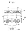
- an apparatus for reproducing a video image including superimposition from an information recording medium on which encoded video information and subcode information having sub-coded superimposition information are recorded comprising video information reproducing means for decoding the video information to output a video signal, subcode information reproducing means for decoding the subcode information to output a superimposition signal, and control means for modifying a format of the superimposition signal to be superimposed on the video signal.
- a format of a superimposition signal e.g., characters, symbols or graphics, etc.. That is, a character size or a character superimposing position, etc. are modified and superimposed on an video signal to be displayed.
- a character displayed are extremely easy to see for a user, especially for aged people or people having a weak eyesight.
- FIG. 1 is an explanatory view showing the principle of the present invention.
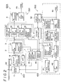
- FIG. 2 is a block diagram showing an embodiment according to the present invention.
- FIG. 3 is a perspective view showing a display/operation unit shown in FIG. 2.
- FIG. 4 is a view for explaining the operation of the present invention.
- FIG. 5 is another view for explaining the operation of the present invention.
- FIG. 6 is a view showing a modification of characters according to the present invention.
- FIG. 1 shows a principle of the present invention
- FIG. 2 shows a detailed configuration of a CDV player according to the present invention
- the CDV player 100A roughly comprises an information reading system 200, an audio reproducing system 300, a video reproducing system 400, and a control system 500.
- the information reading system 200 comprises spindle motor 11 for rotationally driving a CDV disk DK, a pickup 12 for reading information from the CDV disk DK, a servo mechanism 13 for driving the pickup 12, an APC (Automatic Power Control) circuit 14, and a servo unit 1.
- the servo unit 1 comprises a tracking/focus/carriage servo circuit 15 for carrying out a servo control of the pickup 12 and the servo mechanism 13, and a spindle servo circuit 16 for carrying out a servo control of the spindle motor 11.
- the audio reproducing system 300 comprises a preamplifier section 2, a decoder section 3, and a DA converter section 4.
- the preamplifier section 2 comprises an RF amplifier 21, and an error generator 22.
- the decoder section 3 comprises a subcode decoder 23, an audio data decoder 24, a control data decoder 25, and a spindle servo error generator 26.
- the DA converter section 4 comprises a DA converter 27 and a LPF/audio amplifier 28.
- the control system 500 comprises a system controller 31 and a display/operation unit 32.
- the video reproducing system 400 comprises an EFM (Eight to Fourteen Modulation) extractor 41, an RF amplifier 42, a spindle servo error generator 43, a video demodulator 44, a time base correction servo section 45, a time base correction section 46, a blue-back/character generator 47, and a video signal processing section 48.
- EFM Eight to Fourteen Modulation
- the CDV disk DK is rotationally driven by the spindle motor 11, and recorded information is read by irradiating a laser beam B from the pickup 12 and is then converted to an electrical signal.
- the pickup 12 is driven and controlled by the servo mechanism 13 under control of the servo unit 1.
- a light source for irradiating a light beam on a disk a semiconductor laser is generally used.
- the intensity of the output light beam changes in correspondence with the change in temperature or passage of time even when a current input to the semiconductor laser is kept constant, resulting in the change of the electrical signal obtained from the disk. Accordingly, the APC circuit 14 is provided to control the output laser light to be a constant intensity for a long time, even if the temperature changes.
- the electrical signal read by the pickup 12 is sent to the RF amplifier 21 and the error generator 22.
- An output from the RF amplifier 21 is further sent to the audio data decoder 24 and the spindle servo error generator 26.
- the audio signal is decoded and sent to the DA converter 27.
- the output signal from the audio data decoder 24 is also sent to the subcode decoder 23, and the control data decoder 25.
- the DA converter 27 converts the decoded digital audio signal to a corresponding analog signal to send it to the LPF/audio amplifier 28.
- a predetermined frequency band of the converted analog signal is extracted at the low pass filter (LPF), and then the output level thereof is adjusted.
- the signal thus processed is output from the audio output terminal 49 as an audio output signal.
- an external amplifier or an external speaker are connected to the audio output terminal 49, the audio output signal can be output as sound or voice.
- the error generator 22 generates and delivers a tracking error signal, a focusing error signal, and a carriage error signal to the tracking/focus/carriage servo circuit 15 to perform the servo controls on the basis of the error signals.
- the tracking/focus/carriage servo circuit 15 generates a signal for driving the pickup 12 or the servo mechanism 13 on the basis of these error signals and outputs it to the pickup 12 or the servo mechanism 13.
- the spindle servo error generator 26 generates an error signal for a spindle servo control from the signal input from the RF amplifier 21 and outputs it to the spindle servo circuit 16.
- the spindle servo circuit 16 generates a signal for driving the spindle motor 11 on the basis of this error signal and outputs it to the spindle motor 11.
- the subcode decoder 23 decodes and extracts a subcode signal from the signal sent from the audio data decoder 24 and sends it to the blue back/character generator 47.
- the subcode signal superimposition signals such as characters, symbols or graphics, etc. to be superimposed on a reproduced video image are included.
- the blue back character generator 47 extracts the character signals to output them to the video signal processing section 48.
- An output of the pickup 12 is also sent to the EFM extraction section 41 and the RF amplifier 42.
- the signal is subjected to EFM demodulation.
- the signal thus demodulated is fed back to the output side of the RF amplifier 21.
- a signal whose level is adjusted at the RF amplifier 42 is sent to the video demodulation section 44, at which the video signal is demodulated.
- the signal thus demodulated is sent to the spindle servo error generator 43 and the time base correcting section 46.
- the spindle servo error generator 43 outputs an error signal to the spindle servo circuit 16 to carry out a spindle servo control.
- the video signal sent to the time base correcting section 46 is subjected to time base servo correction by the time base correction servo section 45 and the time base correcting section 46, and is then output to the video signal processing section 48.
- the video signal processing section 48 is supplied with a superimposition signal (characters, etc.) to be superimposed from the blue back character generator 47.
- the superimposition signal is superimposed on the video signal, and the signal thus superimposed is output from a video output terminal 50.
- An input operation command is sent to the system controller 31.
- the input operation command includes commands for modifying a format of superimposing the characters, symbols and graphics on the video signal.
- the system controller 31 outputs, on the basis of the input command, a control signal to the control data decoder 25, the tracking/focus/carriage servo circuit 15, the spindle servo circuit 16, the video demodulating section 44, and the blue back character generator 47 to control them.
- the control data decoder 25 decodes control data from the decoded signal sent from the audio data decoder 24 to send it to the system controller 31.
- the tracking/focus/carriage servo circuit 15 and the spindle servo circuit 16 also send servo information to the system controller 31.
- a modification command to double the size of a character of lyrics for musical accompaniment is input from the display/operation unit 32
- the command is sent from the display/operation unit 32 to the blue back character generator 47 to modify a superimposition signal (characters, etc.) in the subcode signal to be double size.
- the modified double-sized character signal is sent from the blue back character generator 47 to the video signal processing section 48 to be superimposed on a background video signal.
- the video output signal thus produced is delivered to an image display device to be reproduced.
- FIG. 3 An example of the display/operation unit 32 is shown FIG. 3.
- input keys K1 to K14 are provided on the display/operation unit 32A.
- the input keys K1 and K2 are used for changing the size of a character, etc. to be superimposed.
- the keys K3 to K6 are used for changing the position of the superimposed character on a reproduced picture.
- the key K3 functions to move the entirety of the characters in an upper direction on the picture
- the key K4 functions to move them in a lower direction
- the key K5 functions to move them in a left direction
- the key K6 functions to move them in a right direction.
- the keys K7 to K9 are used for changing a character style or font wherein the key K7 serves to change the font to a Gothic type
- the key K8 serves to change it to a Ming type
- the key K9 serves to change it to an italic type.
- the keys K10 to K12 are used for designation of color of a character wherein the key K10 serves to designate R (Red), the key K11 serves to designate G (green), and the key K12 serves to designate B (blue).
- the keys K13 and K14 are used for displaying two languages (bilingual display).
- the key K13 is a key for displaying a main language (e.g., Japanese)
- the key K14 is a key for displaying a subsidiary language (e.g., English).
- a subsidiary language e.g., English
- an operator depresses only the key K13 only Japanese is displayed.
- an operator depresses only the key K14 only English is displayed.
- characters of the both languages are displayed.
- FIG. 4(A) shows an example of display of lyrics for musical accompaniment in a normal format. Respective characters have a height L on a displayed picture.
- Respective characters have a height L on a displayed picture.
- decoding subcode information to store data of one field and writing the same data twice for every horizontal synchronizing signal (Hsync)
- Hsync horizontal synchronizing signal
- a reproduced picture is divided into 50 ⁇ 18 sections (fonts) and data of every respective sections are signified by a section position data and a color data.
- each section is further divided into 12 ⁇ 6 pixels and color information of every respective pixels are signified by a WRITE FONT information and an X-OR information.
- coordinates information F (x, y) represents the x-th section position in a vertical direction and the y-th section position in a horizontal direction.
- a color data of each pixel is represented by P ( ⁇ , ⁇ ).
- color data represented by C (x, y, ⁇ , ⁇ ) designates a color data at the pixel of the ⁇ -th vertical position and at the ⁇ -th horizontal position which is in the section of the x-th vertical position and the y-th horizontal position
- a color data of expanded (double height) character is represented by C′ (x, y, ⁇ , ⁇ ).
- each respective color datas of the fonts F′ (x, y) and F′ (x+1, y) (1′, 2′, ... 6′, etc.) are determined in a manner as shown in FIG. 6. Therefore, the double height character can be produced. Further, other modifications such as producing a character having double width or having both double height an width can be carried out.
- the modification of changing a display position of characters can be carried out as follows.
- a character indicated by a font F (x, y) is moved 3 font in a vertical direction (x direction)
- the position of the moved character is determined as a font F′ (x+3, y)
- characters become easy to see as shown in FIG. 5(B) without disturbance by the background image.
- the modification of changing colors of characters can be carried out as follows.
- a color data of a pixel in a font F (x, y) is represented by C (x, y, ⁇ , ⁇ , c)
- the color of the pixel is changed by changing the componet C in the color data, i.e. , changing the color data C (x, y, ⁇ , ⁇ , c) to C′ (x, y, ⁇ , ⁇ , 3c), for example.
- the change of character style can be carried out by changing a component B, i.e., changing the character style data D (x, y, B) to D′ (x, y, B′), for example.
- the character style of displayed characters is modified by way of reading out an character style information, stored in the character generator 47, corresponding to the character style data B′.
- the character modification is advantageously carried out at a high speed and on a real time basis.
- this invention is applicable to an LD player.
- FM modulated video information and voice information are generally recorded on LD.
- this invention can be applied to LD player.
- this invention is applicable to apparatuses in which an image can be displayed such as an OSD (On Screen Display) or a Videotex, etc. , or magnetic recording/reproducing apparatuses such as a VTR (Video Tape Recorder) or a DAT (Digital Audio Taperecorder), etc..
- the recorded information reproducing apparatus can modify position and/or size, etc., of characters, symbols, or graphics so that they become easy to see for a user, especially for aged people or people having a weak eyesight.
Applications Claiming Priority (2)
| Application Number | Priority Date | Filing Date | Title |
|---|---|---|---|
| JP3110619A JPH04337986A (ja) | 1991-05-15 | 1991-05-15 | 記録情報再生装置 |
| JP110619/91 | 1991-05-15 |
Publications (3)
| Publication Number | Publication Date |
|---|---|
| EP0514214A2 true EP0514214A2 (fr) | 1992-11-19 |
| EP0514214A3 EP0514214A3 (en) | 1993-05-26 |
| EP0514214B1 EP0514214B1 (fr) | 1997-04-23 |
Family
ID=14540394
Family Applications (1)
| Application Number | Title | Priority Date | Filing Date |
|---|---|---|---|
| EP19920304442 Expired - Lifetime EP0514214B1 (fr) | 1991-05-15 | 1992-05-15 | Dispositif pour reproduire une information d'image avec superposition |
Country Status (3)
| Country | Link |
|---|---|
| EP (1) | EP0514214B1 (fr) |
| JP (1) | JPH04337986A (fr) |
| DE (1) | DE69219199T2 (fr) |
Cited By (3)
| Publication number | Priority date | Publication date | Assignee | Title |
|---|---|---|---|---|
| EP0777227A1 (fr) * | 1995-05-31 | 1997-06-04 | Sony Corporation | Moyen d'enregistrement, dispositif d'enregistrement, procede de reproduction et dispositif de reproduction |
| US6154427A (en) * | 1997-01-22 | 2000-11-28 | Sony Corporation | Recording medium, recording apparatus, reproducing method, and reproducing apparatus |
| CN111818277A (zh) * | 2020-06-24 | 2020-10-23 | 重庆山淞信息技术有限公司 | 视频图像的字符叠加方法、装置、计算机设备和存储介质 |
Citations (2)
| Publication number | Priority date | Publication date | Assignee | Title |
|---|---|---|---|---|
| EP0380746A2 (fr) * | 1989-01-31 | 1990-08-08 | Pioneer Electronic Corporation | Lecteur de milieux d'enregistrement |
| EP0389689A1 (fr) * | 1989-03-28 | 1990-10-03 | POLYGRAM MANUFACTURING & DISTRIBUTION CENTRES GMBH | Méthode pour la transmission d'un signal de transmission et un dispositif de transmission et un dispositif de réception à utiliser dans cette méthode |
-
1991
- 1991-05-15 JP JP3110619A patent/JPH04337986A/ja active Pending
-
1992
- 1992-05-15 DE DE1992619199 patent/DE69219199T2/de not_active Expired - Fee Related
- 1992-05-15 EP EP19920304442 patent/EP0514214B1/fr not_active Expired - Lifetime
Patent Citations (2)
| Publication number | Priority date | Publication date | Assignee | Title |
|---|---|---|---|---|
| EP0380746A2 (fr) * | 1989-01-31 | 1990-08-08 | Pioneer Electronic Corporation | Lecteur de milieux d'enregistrement |
| EP0389689A1 (fr) * | 1989-03-28 | 1990-10-03 | POLYGRAM MANUFACTURING & DISTRIBUTION CENTRES GMBH | Méthode pour la transmission d'un signal de transmission et un dispositif de transmission et un dispositif de réception à utiliser dans cette méthode |
Cited By (6)
| Publication number | Priority date | Publication date | Assignee | Title |
|---|---|---|---|---|
| EP0777227A1 (fr) * | 1995-05-31 | 1997-06-04 | Sony Corporation | Moyen d'enregistrement, dispositif d'enregistrement, procede de reproduction et dispositif de reproduction |
| EP0777227A4 (fr) * | 1995-05-31 | 1999-04-21 | Sony Corp | Moyen d'enregistrement, dispositif d'enregistrement, procede de reproduction et dispositif de reproduction |
| US5999508A (en) * | 1995-05-31 | 1999-12-07 | Sony Corporation | Recording medium, recording apparatus, reproducing method, and reproducing apparatus |
| US6130870A (en) * | 1995-05-31 | 2000-10-10 | Sony Corporation | Recording medium, recording apparatus, reproducing method, and reproducing device |
| US6154427A (en) * | 1997-01-22 | 2000-11-28 | Sony Corporation | Recording medium, recording apparatus, reproducing method, and reproducing apparatus |
| CN111818277A (zh) * | 2020-06-24 | 2020-10-23 | 重庆山淞信息技术有限公司 | 视频图像的字符叠加方法、装置、计算机设备和存储介质 |
Also Published As
| Publication number | Publication date |
|---|---|
| JPH04337986A (ja) | 1992-11-25 |
| EP0514214A3 (en) | 1993-05-26 |
| DE69219199T2 (de) | 1997-10-30 |
| EP0514214B1 (fr) | 1997-04-23 |
| DE69219199D1 (de) | 1997-05-28 |
Similar Documents
| Publication | Publication Date | Title |
|---|---|---|
| EP0330732B1 (fr) | Procédé et appareil pour l'enregistrement et la reproduction d'information d'image avec information supplémentaire pour modification de l'information d'image reproduite | |
| US5850500A (en) | Recording medium comprising a plurality of different languages which are selectable independently of each other | |
| EP1130575B1 (fr) | Support d'enregistrement d'information et dispositif pour la reproduction de cette information | |
| KR0136025B1 (ko) | 캡션기능을 갖춘 비디오 디스크와 그 재생장치(video compact disc with caption data recorded thereon and system for handling the same) | |
| US5268889A (en) | Display device for a compact disc player and a compact disc | |
| US5315400A (en) | Method of recording and reproducing picture information, recording medium, and recording medium playing apparatus | |
| KR19990037477A (ko) | 기록 매체와 이것을 제조하는 방법 | |
| EP0843312A3 (fr) | Appareil d'édition d'informations de contrÔle pour reproduire d'un train de données de système et un milieu d'enregistrement sur lequel la méthode utilisée est enregistrée | |
| JPH0634304B2 (ja) | デイスク再生装置 | |
| JP4532786B2 (ja) | 画像処理装置及びその方法 | |
| EP0514214B1 (fr) | Dispositif pour reproduire une information d'image avec superposition | |
| US5177619A (en) | Apparatus for minimizing signal degradation during the copying of video signals from one recording medium to another recording medium | |
| US7574105B2 (en) | Device, system, method and program for data processing, recording medium storing the program, and player | |
| EP0289914A2 (fr) | Procédé d'enregistrement et de reproduction d'information sur et à partir d'un disque d'enregistrement | |
| EP0587416A2 (fr) | Appareil de visualisation d'images reproduites et milieu d'enregistrement pour cet appareil | |
| KR19980066044A (ko) | 화상처리기법을 이용한 주인공 얼굴 및 대사를 특정인물로 변환하는 장치 및 저작물 | |
| JPS6115487B2 (fr) | ||
| JPS6343480A (ja) | 情報再生装置 | |
| JPS6115486B2 (fr) | ||
| KR950012230B1 (ko) | 디스크재생시스템의 고속데이터탐색장치 | |
| JPH0261860A (ja) | ビデオディスク再生装置 | |
| JPS6180689A (ja) | デジタルデイスクレコ−ド再生装置 | |
| JPH04367178A (ja) | 磁気記録再生システム | |
| JP3446759B2 (ja) | メモ機能付きビデオテープレコーダ | |
| JPH06205351A (ja) | 記録情報再生装置 |
Legal Events
| Date | Code | Title | Description |
|---|---|---|---|
| PUAI | Public reference made under article 153(3) epc to a published international application that has entered the european phase |
Free format text: ORIGINAL CODE: 0009012 |
|
| AK | Designated contracting states |
Kind code of ref document: A2 Designated state(s): DE FR GB |
|
| PUAL | Search report despatched |
Free format text: ORIGINAL CODE: 0009013 |
|
| AK | Designated contracting states |
Kind code of ref document: A3 Designated state(s): DE FR GB |
|
| 17P | Request for examination filed |
Effective date: 19931123 |
|
| 17Q | First examination report despatched |
Effective date: 19951107 |
|
| GRAG | Despatch of communication of intention to grant |
Free format text: ORIGINAL CODE: EPIDOS AGRA |
|
| GRAH | Despatch of communication of intention to grant a patent |
Free format text: ORIGINAL CODE: EPIDOS IGRA |
|
| GRAH | Despatch of communication of intention to grant a patent |
Free format text: ORIGINAL CODE: EPIDOS IGRA |
|
| GRAA | (expected) grant |
Free format text: ORIGINAL CODE: 0009210 |
|
| AK | Designated contracting states |
Kind code of ref document: B1 Designated state(s): DE FR GB |
|
| PGFP | Annual fee paid to national office [announced via postgrant information from national office to epo] |
Ref country code: GB Payment date: 19970506 Year of fee payment: 6 |
|
| PGFP | Annual fee paid to national office [announced via postgrant information from national office to epo] |
Ref country code: FR Payment date: 19970513 Year of fee payment: 6 |
|
| PGFP | Annual fee paid to national office [announced via postgrant information from national office to epo] |
Ref country code: DE Payment date: 19970523 Year of fee payment: 6 |
|
| REF | Corresponds to: |
Ref document number: 69219199 Country of ref document: DE Date of ref document: 19970528 |
|
| ET | Fr: translation filed | ||
| PLBE | No opposition filed within time limit |
Free format text: ORIGINAL CODE: 0009261 |
|
| STAA | Information on the status of an ep patent application or granted ep patent |
Free format text: STATUS: NO OPPOSITION FILED WITHIN TIME LIMIT |
|
| 26N | No opposition filed | ||
| PG25 | Lapsed in a contracting state [announced via postgrant information from national office to epo] |
Ref country code: GB Free format text: LAPSE BECAUSE OF NON-PAYMENT OF DUE FEES Effective date: 19980515 |
|
| PG25 | Lapsed in a contracting state [announced via postgrant information from national office to epo] |
Ref country code: FR Free format text: LAPSE BECAUSE OF NON-PAYMENT OF DUE FEES Effective date: 19980531 |
|
| GBPC | Gb: european patent ceased through non-payment of renewal fee |
Effective date: 19980515 |
|
| PG25 | Lapsed in a contracting state [announced via postgrant information from national office to epo] |
Ref country code: DE Free format text: LAPSE BECAUSE OF NON-PAYMENT OF DUE FEES Effective date: 19990302 |
|
| REG | Reference to a national code |
Ref country code: FR Ref legal event code: ST |