EP0512837A2 - Ultraschall-Doppler-Abbildungsgerät - Google Patents
Ultraschall-Doppler-Abbildungsgerät Download PDFInfo
- Publication number
- EP0512837A2 EP0512837A2 EP92304129A EP92304129A EP0512837A2 EP 0512837 A2 EP0512837 A2 EP 0512837A2 EP 92304129 A EP92304129 A EP 92304129A EP 92304129 A EP92304129 A EP 92304129A EP 0512837 A2 EP0512837 A2 EP 0512837A2
- Authority
- EP
- European Patent Office
- Prior art keywords
- subtraction
- data
- addition
- implementing
- ultrasonic
- Prior art date
- Legal status (The legal status is an assumption and is not a legal conclusion. Google has not performed a legal analysis and makes no representation as to the accuracy of the status listed.)
- Granted
Links
Images


Classifications
-
- G—PHYSICS
- G01—MEASURING; TESTING
- G01S—RADIO DIRECTION-FINDING; RADIO NAVIGATION; DETERMINING DISTANCE OR VELOCITY BY USE OF RADIO WAVES; LOCATING OR PRESENCE-DETECTING BY USE OF THE REFLECTION OR RERADIATION OF RADIO WAVES; ANALOGOUS ARRANGEMENTS USING OTHER WAVES
- G01S15/00—Systems using the reflection or reradiation of acoustic waves, e.g. sonar systems
- G01S15/02—Systems using the reflection or reradiation of acoustic waves, e.g. sonar systems using reflection of acoustic waves
- G01S15/50—Systems of measurement, based on relative movement of the target
- G01S15/58—Velocity or trajectory determination systems; Sense-of-movement determination systems
- G01S15/582—Velocity or trajectory determination systems; Sense-of-movement determination systems using transmission of interrupted pulse-modulated waves and based upon the Doppler effect resulting from movement of targets
-
- G—PHYSICS
- G01—MEASURING; TESTING
- G01S—RADIO DIRECTION-FINDING; RADIO NAVIGATION; DETERMINING DISTANCE OR VELOCITY BY USE OF RADIO WAVES; LOCATING OR PRESENCE-DETECTING BY USE OF THE REFLECTION OR RERADIATION OF RADIO WAVES; ANALOGOUS ARRANGEMENTS USING OTHER WAVES
- G01S15/00—Systems using the reflection or reradiation of acoustic waves, e.g. sonar systems
- G01S15/88—Sonar systems specially adapted for specific applications
- G01S15/89—Sonar systems specially adapted for specific applications for mapping or imaging
- G01S15/8906—Short-range imaging systems; Acoustic microscope systems using pulse-echo techniques
- G01S15/8979—Combined Doppler and pulse-echo imaging systems
-
- H—ELECTRICITY
- H03—ELECTRONIC CIRCUITRY
- H03D—DEMODULATION OR TRANSFERENCE OF MODULATION FROM ONE CARRIER TO ANOTHER
- H03D3/00—Demodulation of angle-, frequency- or phase- modulated oscillations
- H03D3/007—Demodulation of angle-, frequency- or phase- modulated oscillations by converting the oscillations into two quadrature related signals
-
- H—ELECTRICITY
- H03—ELECTRONIC CIRCUITRY
- H03D—DEMODULATION OR TRANSFERENCE OF MODULATION FROM ONE CARRIER TO ANOTHER
- H03D2200/00—Indexing scheme relating to details of demodulation or transference of modulation from one carrier to another covered by H03D
- H03D2200/0041—Functional aspects of demodulators
- H03D2200/005—Analog to digital conversion
-
- H—ELECTRICITY
- H03—ELECTRONIC CIRCUITRY
- H03D—DEMODULATION OR TRANSFERENCE OF MODULATION FROM ONE CARRIER TO ANOTHER
- H03D2200/00—Indexing scheme relating to details of demodulation or transference of modulation from one carrier to another covered by H03D
- H03D2200/0041—Functional aspects of demodulators
- H03D2200/006—Signal sampling
- H03D2200/0062—Computation of input samples, e.g. successive samples
Definitions
- This invention relates to an ultrasonic Doppler imaging apparatus used for measuring the velocity of blood flow in the human body and the like on a real time basis.
- an ultrasonic Doppler imaging apparatus in which the ultrasonic pulse Doppler measuring method is combined with the pulse reflection method for producing a tomographic image of a diagnostic object such as the heart through the emission of ultrasonic pulse waves to the object body and the detection of reflected ultrasonic pulse waves from the object body, so that the blood flow information and tomographic image (B-mode image) information are obtained by means of a single ultrasonic probe and the blood flow information modulated in color graphics is superimposed on the tomographic image on a real time basis.
- the above-mentioned ultrasonic Doppler imaging apparatus which is disclosed in Japanese Patent Unexamined Publication No. 57-128138, is based on the principle of operation, which will be explained in the following.
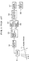
- Fig. 1 shows the basic principle and the arrangement of the conventional ultrasonic Doppler imaging apparatus.
- Symbol Y1 denotes a blood stream
- a, b and c denote emission directions of ultrasonic pulse waves to the blood stream Y1.
- Indicated by 51 is a probe which emits ultrasonic pulse waves to the blood stream Y1 and receives reflected ultrasonic pulse waves from the blood stream
- 52 is a reception circuit which receives a signal of ultrasonic pulse wave from the probe
- 53 is a quadrature phase detection circuit which receives the output signal of the reception circuit and implements quadrature phase detection for the signal
- 54 and 55 are high-pass filters
- 56 is a frequency analyzer which receives the output signals of the high-pass filters and implements the frequency analysis for the signals
- 57 is a frame memory which stores the output of the frequency analyzer
- 58 is a display device.
- the Doppler shift frequency fd is given by the following expression (1).
- fd 2V ⁇ cos( ⁇ ) ⁇ fc/c where V is the blood flow velocity, ⁇ is the incident angle of the ultrasonic beam with the blood vessel, fc is the center frequency, and c is the velocity of sound.
- the blood flow velocity V can be evaluated by detecting the Doppler shift frequency fd.
- the blood flow velocity V is displayed as a two-dimensional image as follows. Initially, the ultrasonic probe 51 emits ultrasonic pulse waves in directions a, b, c, and so on sequentially toward the object body. At the beginning, ultrasonic pulse waves are emitted in the direction a several times, e.g., ten times. Each echo signal produced by Doppler shift reflection by the blood flow in the object body is received by the same probe 51, which converts the echo signal into an electric signal and delivers to the receiving circuit 52. Subsequently, the quadrature phase detection circuit 53 detects the I-channel and Q-channel Doppler shift signals as complex Doppler data. The Doppler shift signals are assessed on 256 sample points, for example, located in the emission direction of ultrasonic pulse waves.
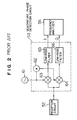
- Fig. 2 shows the arrangement of the quadrature phase detection circuit 53.
- 61 is an oscillator
- 62 is a shifter
- 63 and 64 are mixers
- 65 and 66 are low-pass filters.
- a signal provided by the reception circuit 52 is fed to the mixers.
- the mixer 63 mixes the received signal with a signal generated by the oscillator 61
- the mixer 64 mixes the received signal with the signal provided by the oscillator and phase-shifted by 90° by the shifter 62.
- the mixers 63 and 64 have their outputs fed through the low-pass filters 65 and 66, respectively, and the Doppler shift signals of the I and Q channels are detected.
- the Doppler shift signals at the same sample points i.e., real parts and imaginary parts of ten pieces of complex Doppler data resulting from ten emissions, are rid of low-frequency components caused by the blood vessel wall and the like by means of the respective high-pass filters 54 and 55, and thereafter fed to the frequency analyzer 56.
- the result of analysis is stored in the frame memory 57, and the images of the blood flow velocity component in the emission direction a are displayed on the display device 58.
- the same operation is repeated for the emission directions b, c and so on, and blood flow images of all emission directions (flow velocity distribution images) are displayed on the display device 58.
- the flow velocity distribution images are displayed in color mode by being superimposed on a monochrome tomographic image.
- the foregoing conventional ultrasonic Doppler imaging apparatus which is based on the quadrature phase detection circuit 53 of analog circuit configuration, is deficient in the difficulty in the accurate balancing of the gain and phase of the I and Q channels, and therefore the accuracy of frequency analysis can be deteriorated due to unbalanced circuit parameters of both channels.
- a prime object of the present invention is to provide an ultrasonic Doppler imaging apparatus which is not influenced by the error of an analog phase detection circuit and is capable of performing accurate frequency analysis.
- Another object of this invention is to provide an ultrasonic Doppler imaging apparatus which is capable of measuring the Doppler frequency shift accurately through a less number of arithmetic operations.
- Still another object of this invention is to provide an ultrasonic Doppler imaging apparatus which is capable of displaying the blood flow information and tomographic image accurately on the same frame of picture.
- Still another object of this invention is to provide an ultrasonic Doppler imaging apparatus which is based on a quadrature adder/subtracter of digital configuration so that the gain and phase of the I and Q channels are maintained accurately.
- an inventive ultrasonic Doppler imaging apparatus comprises means of decomposing the received signal in synchronism with emission, means of implementing the quadrature addition/subtraction for the decomposed data string, and means of frequency analysis for implementing the correlative computation for the complex Doppler data produced as the I and Q channel outputs of computation.
- both channels have their gain and phase balanced correctly, and the blood flow velocity can be evaluated accurately.
- the quadrature adder/subtracter is designed to produce the I and q channel outputs through the subtraction between data pieces, which are half phase apart, of the decomposed data string and thereafter through the summation of the results of subtraction.
- Addition/subtraction is implemented with addition/subtraction means for the decomposed data string and the data string delayed with delay means, and results are summed with cumulative summing means thereby to produce the I and Q channel outputs.
- the Doppler shift frequency can be measured accurately through a less number of quadrature adding/subtracting operations.
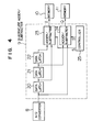
- Fig. 3 shows the arrangement of the apparatus based on the first embodiment of this invention.
- an ultrasonic probe (will be termed simply “probe” hereinafter)
- 2 is a pulse generator which activates the probe 1
- 3 is a pre-amplifier which amplifies the electric signal produced from a reflected ultrasonic wave by the probe
- 4 is a band-pass filter
- 5 is an oscillator which supplies a signal to the drive pulse generator 2 and a mixer 6 which mixes the output of the oscillator 5 with the output of the bandpass filter 4.
- Indicated by 7 is a band-pass filter which extracts prescribed frequency components from the mixer output
- 8 is an A/D converter which converts the analog output of the band-pass filter 7 into digital data
- 9 is a quadrature adder/subtracter which converts the A/D converter output into complex Doppler data through the addition/subtraction operation
- 10 and 11 are memories for storing the output of the quadrature adder/subtracter
- 12 is an address generator which generates addresses for the memories
- 13 and 14 are high-pass filters which extract high-frequency components from the outputs of the memories
- 15 is a correlative operator which implements the frequency analysis for the outputs of the high-pass filters
- 16 is a frame memory
- 17 is a color encoder
- 18 is a display device
- 19 is a detector which implements the detection for the preamplifier output and delivers the detection result to the frame memory.
- the probe 1 is activated by the drive pulse generator 2, and it emits ultrasonic pulse waves in directions indicated by a, b, c and so on sequentially toward the object body, i.e., it implements the sector scanning.
- the ultrasonic pulse wave transmitted has a center frequency of fc, and an ultrasonic pulse wave is emitted several times, e.g., ten times, in the direction of a at the beginning.
- an ultrasonic signal which has been rendered a Doppler shift by being reflected by the blood stream in the object body is received by the same probe 1, and the resulting electric signal is sent for amplification to the pre-amplifier 3 which serves as the reception circuit.
- the outptut signal of the pre-amplifier 3 is detected by the detector 19, and the resulting tomographic image signal of the object body is stored in the frame memory 16.
- the monochrome tomographic image is displayed on the display device 18.
- the output of the preamplifier 3 is, at the same time, received by the band-pass filter 4, by which prescribed frequency components are extracted, and thereafter it is rendered the frequency conversion by being mixed with the output of the oscillator 5 by the mixer 6.
- the band-pass filter 7 removes unwanted frequency components from the mixer output.
- the output of the band-pass filter 7 is converted into digital data in synchronism with emission by the A/D converter 8 which operates in synchronism with the oscillator 5.
- the A/D converter used here has a resolution of 12 bits and a sampling frequency of about fi x 4.
- the resulting digital data is converted into complex Doppler data of I and q channels by the quadrature adder/subtracter 9 as follows.
- the quadrature adder/subtracter 9 is supplied with data Di (1 ⁇ i% ⁇ n) from the A/D converter 8.
- the quadrature adder/subtracter produces complex Doppler data for a set of K, e.g., four, consecutive data pieces.
- the resulting complex Doppler data has its real part R and imaginary part X expressed as follows.
- This relationship is generalized for selected data D i , D i+1 , D i+2 and D i+3 (where i is an odd number) as follows.
- R C i ⁇ D i + C i+2 ⁇ D i+2
- X C i ⁇ D i + C i+2 ⁇ D i+3
- C i (-1) i/2 (i/2: integer operation)
- the expressions (4) and (5) reveal that the period of addition/subtraction has a shift of one data piece between these expressions, and this shift value is a quarter period (90°) with respect to a complete period (360°) of four consecutive data pieces, and on this account the foregoing adding/subtracting operation is called "quadrature addition/subtraction".
- the complex Doppler data R and X which correspond to the analog quadrature phase detection output, are evaluated through the digital computation.
- Complex Doppler data obtained for all sample points, e.g., 256 points, in the emission direction a are stored in the memories 10 and 11.
- the memories store the complex Doppler data resulting from a series of emissions, i.e., ten emissions, in the direction a.
- the correlative operator 15 uses the outputs of the high-pass filters 13 and 14 to calculate the average frequency, i.e., the Doppler shift frequency fd, and its polarity.
- the Doppler shift frequency fd represents the blood flow velocity V as shown by the expression (1), and the polarity represents the direction of blood flow.
- the average frequency is assessed based on the auto-correlation in general, and an alternative method among various other methods is based on the discrete Fourier transformation for obtaining the first-order moment of the frequency from the power spectrum.
- the values of Doppler shift frequency fd or blood flow velocity V evaluated by the correlative operator 15 for all sample points in the emission direction a of ultrasonic pulse waves are stored in the frame memory 16. The same operation is repeated for the remaining emission directions b, c, and so on of ultrasonic pulse waves, and blood flow images (flow velocity distribution images) are produced for the individual emission directions.
- the output of the detector 19 is also stored in the frame memory 16 for producing a tomographic image, as mentioned previously.
- the color encoder 17 appends color information to the blood flow image data read out of the frame memory 16, and the resulting images are displayed on the display device 18. Consequently, the display device 18 displays, by superimposition, the monochrome tomographic image and the color blood flow images, whereby the doctor's diagnosis is made more accurate and easier.
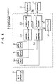
- Fig. 4 is a block diagram showing the arrangement of the first embodiment of the quadrature adder/ subtracter 9 shown in Fig. 3.
- 20 is a data latch which holds the output of the A/D converter 8
- 21 is a data latch which holds the output of the data latch 20
- 22 is a data latch which holds the output of the data latch 21
- 23 is an adder/subtracter which implements subtraction for the outputs of the data latches 20 and
- 24 is an adder/subtracter which implements subtraction for the outputs of the A/D converter 8 and data latch 21, and 25 is a controller.
- An output data string Di provided by the A/D converter 8 is latched into the data latches 20, 21 and 22 sequentially in response to each event j of latch clock. It takes place: at a clock event j, the data latch 20 has input data Dj+3 and output data Dj+2, the data latch 21 has output data Dj+1, and the data latch 22 has output data Dj.
- the controller 25 issues operational commands S to the adder/subtracters 23 and 24 such that the I-channel output of the adder/subtracter 23 is equal to the right side of expression (4) and the Q-channel output of the adder/subtracter 24 is equal to the right side of expression (5).
- the quadrature adder/subtracter 9 produces complex Doppler data R and X as a Doppler shift signal through the digital computation.
- the quadrature adder/subtracter of the first embodiment evaluates the complex Doppler data R and X as a Doppler shift signal for a data string converted from the received signal by the A/D converter 8, and it can balance the gain and phase of both channels accurately and enables high-accuracy measurement of the Doppler shift frequency.
- Fig. 5 is a block diagram showing the arrangement of the second embodiment of the quadrature adder/ subtracter 9.
- 30 is a data latch which holds the output of the A/D converter 8
- 31 is a data latch which holds the output of the data latch 30
- 32 is a data latch which holds the output of the data latch 31
- 33 is an adder/subtracter which implements subtraction for the outputs of the data latches 30 and 32
- 34 is an adder/subtracter which implements subtraction for the outputs of the A/D converter 8 and data latch
- 35 is a cumulative adder which implements cumulative summation for the outputs of the adder/subtracter 33 and delivers the result to a memory 10
- 36 is a cumulative adder which implements cumulative summation for the outputs of the adder/subtracter 34 and delivers the result to a memory 11
- 37 is a controller which issues operational commands S to the cumulative adders.
- the interval between data D1 and D5 being defined to be one period
- the interval between D1 and D3 and between D2 and D4 is equal to a half period (1/2 phase).
- complex Doppler data can be obtained for any data Di (1 ⁇ j ⁇ n, where n > 4).
- the cumulative adders 35 and 36 have their operation controlled for each clock event j by the operational commands S issued by the controller 37.
- the quadrature adder/subtracter of the second embodiment evaluates the complex Doppler data R and X as a Doppler shift signal for a data string converted from the received signal by the A/D converter 8 through the subtraction between data which are 1/2 phase apart and the summation for the results of subtraction, and it can balance the gain and phase of both channels accurately and enables high-accuracy measurement of the Doppler shift frequency through a less number of adding/ subtracting operations.
- Fig. 6 is a block diagram showing the arrangement of the third embodiment of the quadrature adder/ subtracter 9.
- 40 is a data latch which holds the output of the A/D converter 8
- 41 is a data delay device which delays the output of the data latch 40
- 42 is a subtracter which implements subtraction for the outputs of the data latch 40
- data delay device 41, 43 and 44 are cumulative adder/subtracters which implement cumulative summation/subtraction for the outputs of the subtracter 42 and deliver the results to memories 10 and 11, and 45 is a controller which issues operational commands S.
- An output data string Di provided by the A/D converter 8 is latched into the data latch 40 in response to each event j of latch clock.
- the data delay device 41 and cumulative adder/subtracters 43 and 44 are cleared.
- the input G and output H of the data delay device 41, the output ⁇ of the subtracter 42, the output A of the cumulative adder/subtracter 43, and the output B of the cumulative adder/subtracter 44 at each successive clock event are expressed as follows.
- the cumulative adder/subtracters 43 and 44 have their adding or subtracting operation for the output ⁇ of subtracter 42 selected in response to the operational command S from the controller 45.
- the adder/subtracter 43 produces outputs which match the values R of expression (4) and the adder/subtracter 44 produces outputs which match the values of X of expression (5) at successive clock events.
- the third embodiment of quadrature adder/subtracter 9 which is formed of the data delay device 41, subtracter 42 and cumulative adder/subtracters 43 and 44, evaluates the complex Doppler data R and X as a Doppler shift signal for a data string converted from the received signal by the A/D converter 8, and it can balance the gain and phase of both channels accurately and enables high-accuracy measurement of the Doppler shift frequency through a less number of adding/subtracting operations.
Applications Claiming Priority (2)
| Application Number | Priority Date | Filing Date | Title |
|---|---|---|---|
| JP3105479A JPH04336056A (ja) | 1991-05-10 | 1991-05-10 | 超音波ドプラ映像装置 |
| JP105479/91 | 1991-05-10 |
Publications (3)
| Publication Number | Publication Date |
|---|---|
| EP0512837A2 true EP0512837A2 (de) | 1992-11-11 |
| EP0512837A3 EP0512837A3 (de) | 1992-11-25 |
| EP0512837B1 EP0512837B1 (de) | 1996-07-10 |
Family
ID=14408726
Family Applications (1)
| Application Number | Title | Priority Date | Filing Date |
|---|---|---|---|
| EP92304129A Expired - Lifetime EP0512837B1 (de) | 1991-05-10 | 1992-05-07 | Ultraschall-Doppler-Abbildungsgerät |
Country Status (4)
| Country | Link |
|---|---|
| US (1) | US5311870A (de) |
| EP (1) | EP0512837B1 (de) |
| JP (1) | JPH04336056A (de) |
| DE (1) | DE69212066T2 (de) |
Families Citing this family (5)
| Publication number | Priority date | Publication date | Assignee | Title |
|---|---|---|---|---|
| US5483964A (en) * | 1995-05-15 | 1996-01-16 | Ge Yokogawa Medical Systems, Ltd. | Method of detecting moving velocity of tissue or blood and ultrasonic diagnosing apparatus |
| US6537222B1 (en) * | 1997-08-26 | 2003-03-25 | Koninklijke Philips Electronics N.V. | Methods for the detection of contrast agents in ultrasonic imaging |
| KR100232257B1 (ko) * | 1997-09-04 | 1999-12-01 | 이민화 | 클러터신호의 과도응답을 최소로 하는 초음파칼라도플러영상시스템 |
| JP4444008B2 (ja) * | 2004-06-02 | 2010-03-31 | パナソニック株式会社 | 超音波診断装置 |
| RU2007127133A (ru) * | 2007-07-16 | 2007-11-20 | ЗАО Научно-исследовательский центр "Икар" (RU) | Способ детектирования кластерной структуры и микрокластеров жидкости |
Citations (3)
| Publication number | Priority date | Publication date | Assignee | Title |
|---|---|---|---|---|
| GB2144288A (en) * | 1983-07-29 | 1985-02-27 | Rca Corp | Method and apparatus for fm demodulation |
| EP0197854A1 (de) * | 1985-04-05 | 1986-10-15 | Cgr Ultrasonic | Ultraschallabbildungsgerät |
| EP0228069A2 (de) * | 1985-12-26 | 1987-07-08 | Aloka Co. Ltd. | Blutströmung-Ultraschallabbildungsgerät |
Family Cites Families (2)
| Publication number | Priority date | Publication date | Assignee | Title |
|---|---|---|---|---|
| JPS57128138A (en) * | 1981-02-02 | 1982-08-09 | Tokyo Shibaura Electric Co | Ultrasonic diagnostic apparatus |
| JPH07106202B2 (ja) * | 1988-12-21 | 1995-11-15 | 松下電器産業株式会社 | 超音波ドップラ血流計 |
-
1991
- 1991-05-10 JP JP3105479A patent/JPH04336056A/ja active Pending
-
1992
- 1992-05-05 US US07/878,623 patent/US5311870A/en not_active Expired - Fee Related
- 1992-05-07 DE DE69212066T patent/DE69212066T2/de not_active Expired - Fee Related
- 1992-05-07 EP EP92304129A patent/EP0512837B1/de not_active Expired - Lifetime
Patent Citations (3)
| Publication number | Priority date | Publication date | Assignee | Title |
|---|---|---|---|---|
| GB2144288A (en) * | 1983-07-29 | 1985-02-27 | Rca Corp | Method and apparatus for fm demodulation |
| EP0197854A1 (de) * | 1985-04-05 | 1986-10-15 | Cgr Ultrasonic | Ultraschallabbildungsgerät |
| EP0228069A2 (de) * | 1985-12-26 | 1987-07-08 | Aloka Co. Ltd. | Blutströmung-Ultraschallabbildungsgerät |
Non-Patent Citations (1)
| Title |
|---|
| RECORD OF THE 23RD ASILOMAR CONFERENCE ON SIGNALS, SYSTEMS AND COMPUTERS 30 October 1989, PACIFIC GROVE CA US pages 279 - 283 F.F. YASSA 'Accurate detection of Doppler shifts and frequency modulation using an adaptive DSBSC-AM detection method' * |
Also Published As
| Publication number | Publication date |
|---|---|
| DE69212066D1 (de) | 1996-08-14 |
| EP0512837B1 (de) | 1996-07-10 |
| US5311870A (en) | 1994-05-17 |
| EP0512837A3 (de) | 1992-11-25 |
| DE69212066T2 (de) | 1997-02-06 |
| JPH04336056A (ja) | 1992-11-24 |
Similar Documents
| Publication | Publication Date | Title |
|---|---|---|
| US4993417A (en) | Method and system for controlling ultrasound scanning sequence | |
| US6406430B1 (en) | Ultrasound image display by combining enhanced flow imaging in B-mode and color flow mode | |
| EP0092841B1 (de) | Ultraschall-Diagnostikgerät | |
| US4848354A (en) | Method and apparatus for investigating a circulatory system in living biological structures | |
| US6095980A (en) | Pulse inversion doppler ultrasonic diagnostic imaging | |
| US6859659B1 (en) | Estimation of vector velocity | |
| US4800891A (en) | Doppler velocity processing method and apparatus | |
| EP0144968B1 (de) | Ultraschall-Diagnostik-Gerät | |
| US4660565A (en) | Ultrasonic imaging apparatus using pulsed Doppler signal | |
| US4742830A (en) | Ultrasonic diagnosis apparatus for displaying the distribution of speed of movement of an internal part of a living body | |
| JPH0693890B2 (ja) | 超音波診断装置 | |
| EP0228070A2 (de) | Mit Doppler-Effekt arbeitendes Ultraschall-Diagnosegerät | |
| US4799490A (en) | Doppler ultrasonic diagnostic apparatus | |
| EP0312059B1 (de) | Ultraschalldiagnostikgerät | |
| US4911171A (en) | Ultrasonic blood flow imaging apparatus | |
| US5311870A (en) | Ultrasonic Doppler imaging apparatus | |
| US6544184B1 (en) | Imaging with reduced artifacts for medical diagnostic ultrasound | |
| US7803114B2 (en) | Ultrasonic diagnostic apparatus and data processing method therefor | |
| JP3177677B2 (ja) | 超音波連続波ドプラ血流計 | |
| JP2563656B2 (ja) | 超音波ドプラ映像装置 | |
| JP3352211B2 (ja) | 超音波ドプラ診断装置 | |
| JPS61751A (ja) | 超音波媒体の特性測定装置 | |
| JP3391578B2 (ja) | 相関装置および流れ情報表示装置 | |
| JPH0523334A (ja) | 超音波ドプラ映像装置 | |
| JP2788926B2 (ja) | ドプラ法による速度評価方法と装置 |
Legal Events
| Date | Code | Title | Description |
|---|---|---|---|
| PUAI | Public reference made under article 153(3) epc to a published international application that has entered the european phase |
Free format text: ORIGINAL CODE: 0009012 |
|
| PUAL | Search report despatched |
Free format text: ORIGINAL CODE: 0009013 |
|
| AK | Designated contracting states |
Kind code of ref document: A2 Designated state(s): DE FR GB |
|
| AK | Designated contracting states |
Kind code of ref document: A3 Designated state(s): DE FR GB |
|
| 17P | Request for examination filed |
Effective date: 19930107 |
|
| 17Q | First examination report despatched |
Effective date: 19940905 |
|
| GRAA | (expected) grant |
Free format text: ORIGINAL CODE: 0009210 |
|
| AK | Designated contracting states |
Kind code of ref document: B1 Designated state(s): DE FR GB |
|
| GRAH | Despatch of communication of intention to grant a patent |
Free format text: ORIGINAL CODE: EPIDOS IGRA |
|
| REF | Corresponds to: |
Ref document number: 69212066 Country of ref document: DE Date of ref document: 19960814 |
|
| ET | Fr: translation filed | ||
| ET | Fr: translation filed | ||
| PLBE | No opposition filed within time limit |
Free format text: ORIGINAL CODE: 0009261 |
|
| STAA | Information on the status of an ep patent application or granted ep patent |
Free format text: STATUS: NO OPPOSITION FILED WITHIN TIME LIMIT |
|
| 26N | No opposition filed | ||
| REG | Reference to a national code |
Ref country code: GB Ref legal event code: IF02 |
|
| PGFP | Annual fee paid to national office [announced via postgrant information from national office to epo] |
Ref country code: GB Payment date: 20050504 Year of fee payment: 14 |
|
| PGFP | Annual fee paid to national office [announced via postgrant information from national office to epo] |
Ref country code: DE Payment date: 20050506 Year of fee payment: 14 |
|
| PGFP | Annual fee paid to national office [announced via postgrant information from national office to epo] |
Ref country code: FR Payment date: 20050511 Year of fee payment: 14 |
|
| PG25 | Lapsed in a contracting state [announced via postgrant information from national office to epo] |
Ref country code: GB Free format text: LAPSE BECAUSE OF NON-PAYMENT OF DUE FEES Effective date: 20060507 |
|
| PG25 | Lapsed in a contracting state [announced via postgrant information from national office to epo] |
Ref country code: DE Free format text: LAPSE BECAUSE OF NON-PAYMENT OF DUE FEES Effective date: 20061201 |
|
| GBPC | Gb: european patent ceased through non-payment of renewal fee |
Effective date: 20060507 |
|
| REG | Reference to a national code |
Ref country code: FR Ref legal event code: ST Effective date: 20070131 |
|
| PG25 | Lapsed in a contracting state [announced via postgrant information from national office to epo] |
Ref country code: FR Free format text: LAPSE BECAUSE OF NON-PAYMENT OF DUE FEES Effective date: 20060531 |