EP0512736B1 - Ultrafiltration processes for the recovery of polymeric latices from whitewater, and apparatus therefor - Google Patents
Ultrafiltration processes for the recovery of polymeric latices from whitewater, and apparatus therefor Download PDFInfo
- Publication number
- EP0512736B1 EP0512736B1 EP92303831A EP92303831A EP0512736B1 EP 0512736 B1 EP0512736 B1 EP 0512736B1 EP 92303831 A EP92303831 A EP 92303831A EP 92303831 A EP92303831 A EP 92303831A EP 0512736 B1 EP0512736 B1 EP 0512736B1
- Authority
- EP
- European Patent Office
- Prior art keywords
- whitewater
- latex
- ultrafiltration
- membrane
- polymer latex
- Prior art date
- Legal status (The legal status is an assumption and is not a legal conclusion. Google has not performed a legal analysis and makes no representation as to the accuracy of the status listed.)
- Revoked
Links
- 229920000126 latex Polymers 0.000 title claims abstract description 99
- 238000000108 ultra-filtration Methods 0.000 title claims abstract description 54
- 238000011084 recovery Methods 0.000 title claims description 12
- 229920000642 polymer Polymers 0.000 claims abstract description 89
- 239000004816 latex Substances 0.000 claims abstract description 85
- 239000000839 emulsion Substances 0.000 claims abstract description 53
- 238000004519 manufacturing process Methods 0.000 claims abstract description 12
- 239000012528 membrane Substances 0.000 claims description 109
- 238000000034 method Methods 0.000 claims description 43
- 230000008569 process Effects 0.000 claims description 40
- 239000000835 fiber Substances 0.000 claims description 38
- 239000000047 product Substances 0.000 claims description 37
- 239000007787 solid Substances 0.000 claims description 31
- 239000004094 surface-active agent Substances 0.000 claims description 11
- 229920002492 poly(sulfone) Polymers 0.000 claims description 8
- 238000005406 washing Methods 0.000 claims description 5
- 239000000126 substance Substances 0.000 claims description 4
- FGUUSXIOTUKUDN-IBGZPJMESA-N C1(=CC=CC=C1)N1C2=C(NC([C@H](C1)NC=1OC(=NN=1)C1=CC=CC=C1)=O)C=CC=C2 Chemical compound C1(=CC=CC=C1)N1C2=C(NC([C@H](C1)NC=1OC(=NN=1)C1=CC=CC=C1)=O)C=CC=C2 FGUUSXIOTUKUDN-IBGZPJMESA-N 0.000 claims description 3
- 238000004064 recycling Methods 0.000 claims description 3
- 238000011144 upstream manufacturing Methods 0.000 claims description 3
- 230000000737 periodic effect Effects 0.000 claims description 2
- GNFTZDOKVXKIBK-UHFFFAOYSA-N 3-(2-methoxyethoxy)benzohydrazide Chemical compound COCCOC1=CC=CC(C(=O)NN)=C1 GNFTZDOKVXKIBK-UHFFFAOYSA-N 0.000 claims 2
- 239000012467 final product Substances 0.000 claims 1
- 239000002699 waste material Substances 0.000 abstract description 10
- 230000000593 degrading effect Effects 0.000 abstract description 2
- 238000004140 cleaning Methods 0.000 description 41
- 230000004907 flux Effects 0.000 description 28
- 239000000463 material Substances 0.000 description 26
- XLYOFNOQVPJJNP-UHFFFAOYSA-N water Substances O XLYOFNOQVPJJNP-UHFFFAOYSA-N 0.000 description 20
- 239000012466 permeate Substances 0.000 description 18
- VVQNEPGJFQJSBK-UHFFFAOYSA-N Methyl methacrylate Chemical compound COC(=O)C(C)=C VVQNEPGJFQJSBK-UHFFFAOYSA-N 0.000 description 14
- 239000012510 hollow fiber Substances 0.000 description 13
- 239000007788 liquid Substances 0.000 description 11
- 238000000576 coating method Methods 0.000 description 10
- 239000000203 mixture Substances 0.000 description 10
- 238000005086 pumping Methods 0.000 description 10
- 230000002441 reversible effect Effects 0.000 description 10
- 239000000243 solution Substances 0.000 description 9
- 238000012360 testing method Methods 0.000 description 8
- 239000012530 fluid Substances 0.000 description 7
- 239000002245 particle Substances 0.000 description 7
- -1 styrenics Polymers 0.000 description 7
- HEMHJVSKTPXQMS-UHFFFAOYSA-M Sodium hydroxide Chemical compound [OH-].[Na+] HEMHJVSKTPXQMS-UHFFFAOYSA-M 0.000 description 6
- 239000004753 textile Substances 0.000 description 6
- 231100000989 no adverse effect Toxicity 0.000 description 5
- 239000003973 paint Substances 0.000 description 5
- 239000011148 porous material Substances 0.000 description 5
- KAKZBPTYRLMSJV-UHFFFAOYSA-N Butadiene Chemical compound C=CC=C KAKZBPTYRLMSJV-UHFFFAOYSA-N 0.000 description 4
- 239000012141 concentrate Substances 0.000 description 4
- 239000008367 deionised water Substances 0.000 description 4
- 229910021641 deionized water Inorganic materials 0.000 description 4
- 230000001687 destabilization Effects 0.000 description 4
- 238000011045 prefiltration Methods 0.000 description 4
- 238000012545 processing Methods 0.000 description 4
- 239000012465 retentate Substances 0.000 description 4
- 239000002904 solvent Substances 0.000 description 4
- NIXOWILDQLNWCW-UHFFFAOYSA-N acrylic acid group Chemical group C(C=C)(=O)O NIXOWILDQLNWCW-UHFFFAOYSA-N 0.000 description 3
- 239000000853 adhesive Substances 0.000 description 3
- 230000001070 adhesive effect Effects 0.000 description 3
- 229920001577 copolymer Polymers 0.000 description 3
- 238000001914 filtration Methods 0.000 description 3
- 238000002156 mixing Methods 0.000 description 3
- 239000000178 monomer Substances 0.000 description 3
- 239000005416 organic matter Substances 0.000 description 3
- MYRTYDVEIRVNKP-UHFFFAOYSA-N 1,2-Divinylbenzene Chemical compound C=CC1=CC=CC=C1C=C MYRTYDVEIRVNKP-UHFFFAOYSA-N 0.000 description 2
- DHMQDGOQFOQNFH-UHFFFAOYSA-N Glycine Chemical compound NCC(O)=O DHMQDGOQFOQNFH-UHFFFAOYSA-N 0.000 description 2
- RRHGJUQNOFWUDK-UHFFFAOYSA-N Isoprene Chemical compound CC(=C)C=C RRHGJUQNOFWUDK-UHFFFAOYSA-N 0.000 description 2
- 239000004695 Polyether sulfone Substances 0.000 description 2
- 150000001252 acrylic acid derivatives Chemical class 0.000 description 2
- 230000032683 aging Effects 0.000 description 2
- 230000008901 benefit Effects 0.000 description 2
- SRSXLGNVWSONIS-UHFFFAOYSA-N benzenesulfonic acid Chemical compound OS(=O)(=O)C1=CC=CC=C1 SRSXLGNVWSONIS-UHFFFAOYSA-N 0.000 description 2
- 229940092714 benzenesulfonic acid Drugs 0.000 description 2
- 239000011230 binding agent Substances 0.000 description 2
- 230000015572 biosynthetic process Effects 0.000 description 2
- 239000006227 byproduct Substances 0.000 description 2
- 239000000919 ceramic Substances 0.000 description 2
- 230000015271 coagulation Effects 0.000 description 2
- 238000005345 coagulation Methods 0.000 description 2
- 238000001816 cooling Methods 0.000 description 2
- 230000000694 effects Effects 0.000 description 2
- 150000002148 esters Chemical class 0.000 description 2
- 230000005484 gravity Effects 0.000 description 2
- 238000012423 maintenance Methods 0.000 description 2
- 150000002734 metacrylic acid derivatives Chemical class 0.000 description 2
- 125000005395 methacrylic acid group Chemical class 0.000 description 2
- 238000012986 modification Methods 0.000 description 2
- 230000004048 modification Effects 0.000 description 2
- 239000004745 nonwoven fabric Substances 0.000 description 2
- 239000013618 particulate matter Substances 0.000 description 2
- 230000010287 polarization Effects 0.000 description 2
- 229920006393 polyether sulfone Polymers 0.000 description 2
- 150000003839 salts Chemical class 0.000 description 2
- 238000002791 soaking Methods 0.000 description 2
- 239000011343 solid material Substances 0.000 description 2
- 239000008399 tap water Substances 0.000 description 2
- 235000020679 tap water Nutrition 0.000 description 2
- DBCAQXHNJOFNGC-UHFFFAOYSA-N 4-bromo-1,1,1-trifluorobutane Chemical compound FC(F)(F)CCCBr DBCAQXHNJOFNGC-UHFFFAOYSA-N 0.000 description 1
- 239000004925 Acrylic resin Substances 0.000 description 1
- 229920000178 Acrylic resin Polymers 0.000 description 1
- NLHHRLWOUZZQLW-UHFFFAOYSA-N Acrylonitrile Chemical compound C=CC#N NLHHRLWOUZZQLW-UHFFFAOYSA-N 0.000 description 1
- 238000012935 Averaging Methods 0.000 description 1
- 239000004971 Cross linker Substances 0.000 description 1
- 241000196324 Embryophyta Species 0.000 description 1
- 239000004471 Glycine Substances 0.000 description 1
- GYCMBHHDWRMZGG-UHFFFAOYSA-N Methylacrylonitrile Chemical compound CC(=C)C#N GYCMBHHDWRMZGG-UHFFFAOYSA-N 0.000 description 1
- 239000000020 Nitrocellulose Substances 0.000 description 1
- 206010067482 No adverse event Diseases 0.000 description 1
- 239000004677 Nylon Substances 0.000 description 1
- 240000005428 Pistacia lentiscus Species 0.000 description 1
- 239000004952 Polyamide Substances 0.000 description 1
- 239000004698 Polyethylene Substances 0.000 description 1
- 239000004721 Polyphenylene oxide Substances 0.000 description 1
- 239000004743 Polypropylene Substances 0.000 description 1
- 239000005708 Sodium hypochlorite Substances 0.000 description 1
- PPBRXRYQALVLMV-UHFFFAOYSA-N Styrene Natural products C=CC1=CC=CC=C1 PPBRXRYQALVLMV-UHFFFAOYSA-N 0.000 description 1
- GSEJCLTVZPLZKY-UHFFFAOYSA-N Triethanolamine Chemical compound OCCN(CCO)CCO GSEJCLTVZPLZKY-UHFFFAOYSA-N 0.000 description 1
- XTXRWKRVRITETP-UHFFFAOYSA-N Vinyl acetate Chemical compound CC(=O)OC=C XTXRWKRVRITETP-UHFFFAOYSA-N 0.000 description 1
- FJWGYAHXMCUOOM-QHOUIDNNSA-N [(2s,3r,4s,5r,6r)-2-[(2r,3r,4s,5r,6s)-4,5-dinitrooxy-2-(nitrooxymethyl)-6-[(2r,3r,4s,5r,6s)-4,5,6-trinitrooxy-2-(nitrooxymethyl)oxan-3-yl]oxyoxan-3-yl]oxy-3,5-dinitrooxy-6-(nitrooxymethyl)oxan-4-yl] nitrate Chemical compound O([C@@H]1O[C@@H]([C@H]([C@H](O[N+]([O-])=O)[C@H]1O[N+]([O-])=O)O[C@H]1[C@@H]([C@@H](O[N+]([O-])=O)[C@H](O[N+]([O-])=O)[C@@H](CO[N+]([O-])=O)O1)O[N+]([O-])=O)CO[N+](=O)[O-])[C@@H]1[C@@H](CO[N+]([O-])=O)O[C@@H](O[N+]([O-])=O)[C@H](O[N+]([O-])=O)[C@H]1O[N+]([O-])=O FJWGYAHXMCUOOM-QHOUIDNNSA-N 0.000 description 1
- GPFIZJURHXINSQ-UHFFFAOYSA-N acetic acid;nitric acid Chemical compound CC(O)=O.O[N+]([O-])=O GPFIZJURHXINSQ-UHFFFAOYSA-N 0.000 description 1
- 229920005822 acrylic binder Polymers 0.000 description 1
- 229920006397 acrylic thermoplastic Polymers 0.000 description 1
- 239000002671 adjuvant Substances 0.000 description 1
- 150000001298 alcohols Chemical class 0.000 description 1
- 150000003863 ammonium salts Chemical class 0.000 description 1
- 125000000129 anionic group Chemical group 0.000 description 1
- 239000003945 anionic surfactant Substances 0.000 description 1
- 238000013459 approach Methods 0.000 description 1
- 239000008346 aqueous phase Substances 0.000 description 1
- 239000004760 aramid Substances 0.000 description 1
- 229920003235 aromatic polyamide Polymers 0.000 description 1
- 239000010426 asphalt Substances 0.000 description 1
- 238000011001 backwashing Methods 0.000 description 1
- 238000010923 batch production Methods 0.000 description 1
- 230000000740 bleeding effect Effects 0.000 description 1
- 230000015556 catabolic process Effects 0.000 description 1
- 239000003093 cationic surfactant Substances 0.000 description 1
- 239000003518 caustics Substances 0.000 description 1
- 229920002678 cellulose Polymers 0.000 description 1
- 239000001913 cellulose Substances 0.000 description 1
- 229920002301 cellulose acetate Polymers 0.000 description 1
- 239000007795 chemical reaction product Substances 0.000 description 1
- 239000003153 chemical reaction reagent Substances 0.000 description 1
- 239000003795 chemical substances by application Substances 0.000 description 1
- 239000012459 cleaning agent Substances 0.000 description 1
- 239000011248 coating agent Substances 0.000 description 1
- 239000002131 composite material Substances 0.000 description 1
- 150000001875 compounds Chemical class 0.000 description 1
- 239000000356 contaminant Substances 0.000 description 1
- 238000010924 continuous production Methods 0.000 description 1
- 238000012864 cross contamination Methods 0.000 description 1
- 238000009295 crossflow filtration Methods 0.000 description 1
- 230000007423 decrease Effects 0.000 description 1
- 238000006731 degradation reaction Methods 0.000 description 1
- 230000002939 deleterious effect Effects 0.000 description 1
- 230000000368 destabilizing effect Effects 0.000 description 1
- 150000001993 dienes Chemical class 0.000 description 1
- 238000007865 diluting Methods 0.000 description 1
- 238000010790 dilution Methods 0.000 description 1
- 239000012895 dilution Substances 0.000 description 1
- 125000000118 dimethyl group Chemical group [H]C([H])([H])* 0.000 description 1
- 230000007613 environmental effect Effects 0.000 description 1
- 125000001495 ethyl group Chemical group [H]C([H])([H])C([H])([H])* 0.000 description 1
- STVZJERGLQHEKB-UHFFFAOYSA-N ethylene glycol dimethacrylate Substances CC(=C)C(=O)OCCOC(=O)C(C)=C STVZJERGLQHEKB-UHFFFAOYSA-N 0.000 description 1
- 239000004744 fabric Substances 0.000 description 1
- 239000000945 filler Substances 0.000 description 1
- 239000002529 flux (metallurgy) Substances 0.000 description 1
- 238000009472 formulation Methods 0.000 description 1
- 238000007710 freezing Methods 0.000 description 1
- 230000008014 freezing Effects 0.000 description 1
- 108700039708 galantide Proteins 0.000 description 1
- 239000011521 glass Substances 0.000 description 1
- 238000010438 heat treatment Methods 0.000 description 1
- LNMQRPPRQDGUDR-UHFFFAOYSA-N hexyl prop-2-enoate Chemical class CCCCCCOC(=O)C=C LNMQRPPRQDGUDR-UHFFFAOYSA-N 0.000 description 1
- 239000006115 industrial coating Substances 0.000 description 1
- 239000000976 ink Substances 0.000 description 1
- 125000001449 isopropyl group Chemical group [H]C([H])([H])C([H])(*)C([H])([H])[H] 0.000 description 1
- 238000004900 laundering Methods 0.000 description 1
- 239000006210 lotion Substances 0.000 description 1
- 239000011159 matrix material Substances 0.000 description 1
- 239000000155 melt Substances 0.000 description 1
- 238000005374 membrane filtration Methods 0.000 description 1
- 229910021645 metal ion Inorganic materials 0.000 description 1
- 125000002496 methyl group Chemical group [H]C([H])([H])* 0.000 description 1
- 229920001220 nitrocellulos Polymers 0.000 description 1
- 239000002736 nonionic surfactant Substances 0.000 description 1
- 229920001778 nylon Polymers 0.000 description 1
- 239000011368 organic material Substances 0.000 description 1
- 239000003960 organic solvent Substances 0.000 description 1
- PNJWIWWMYCMZRO-UHFFFAOYSA-N pent‐4‐en‐2‐one Natural products CC(=O)CC=C PNJWIWWMYCMZRO-UHFFFAOYSA-N 0.000 description 1
- 230000000704 physical effect Effects 0.000 description 1
- 239000004033 plastic Substances 0.000 description 1
- 229920003023 plastic Polymers 0.000 description 1
- 229920003229 poly(methyl methacrylate) Polymers 0.000 description 1
- 229920002239 polyacrylonitrile Polymers 0.000 description 1
- 229920002647 polyamide Polymers 0.000 description 1
- 229920000728 polyester Polymers 0.000 description 1
- 229920000573 polyethylene Polymers 0.000 description 1
- 230000000379 polymerizing effect Effects 0.000 description 1
- 229920006380 polyphenylene oxide Polymers 0.000 description 1
- 229920001155 polypropylene Polymers 0.000 description 1
- 229920000915 polyvinyl chloride Polymers 0.000 description 1
- 239000004800 polyvinyl chloride Substances 0.000 description 1
- 238000002360 preparation method Methods 0.000 description 1
- 238000007639 printing Methods 0.000 description 1
- FBCQUCJYYPMKRO-UHFFFAOYSA-N prop-2-enyl 2-methylprop-2-enoate Chemical compound CC(=C)C(=O)OCC=C FBCQUCJYYPMKRO-UHFFFAOYSA-N 0.000 description 1
- 230000003134 recirculating effect Effects 0.000 description 1
- 229920005989 resin Polymers 0.000 description 1
- 239000011347 resin Substances 0.000 description 1
- 238000010008 shearing Methods 0.000 description 1
- SUKJFIGYRHOWBL-UHFFFAOYSA-N sodium hypochlorite Chemical compound [Na+].Cl[O-] SUKJFIGYRHOWBL-UHFFFAOYSA-N 0.000 description 1
- 238000005507 spraying Methods 0.000 description 1
- 150000003457 sulfones Chemical class 0.000 description 1
- ISXSCDLOGDJUNJ-UHFFFAOYSA-N tert-butyl prop-2-enoate Chemical compound CC(C)(C)OC(=O)C=C ISXSCDLOGDJUNJ-UHFFFAOYSA-N 0.000 description 1
- 238000010257 thawing Methods 0.000 description 1
- 239000002562 thickening agent Substances 0.000 description 1
- 230000007704 transition Effects 0.000 description 1
- 229920002554 vinyl polymer Polymers 0.000 description 1
Images
Classifications
-
- B—PERFORMING OPERATIONS; TRANSPORTING
- B01—PHYSICAL OR CHEMICAL PROCESSES OR APPARATUS IN GENERAL
- B01D—SEPARATION
- B01D61/00—Processes of separation using semi-permeable membranes, e.g. dialysis, osmosis or ultrafiltration; Apparatus, accessories or auxiliary operations specially adapted therefor
- B01D61/14—Ultrafiltration; Microfiltration
- B01D61/145—Ultrafiltration
-
- C—CHEMISTRY; METALLURGY
- C08—ORGANIC MACROMOLECULAR COMPOUNDS; THEIR PREPARATION OR CHEMICAL WORKING-UP; COMPOSITIONS BASED THEREON
- C08F—MACROMOLECULAR COMPOUNDS OBTAINED BY REACTIONS ONLY INVOLVING CARBON-TO-CARBON UNSATURATED BONDS
- C08F6/00—Post-polymerisation treatments
-
- B—PERFORMING OPERATIONS; TRANSPORTING
- B01—PHYSICAL OR CHEMICAL PROCESSES OR APPARATUS IN GENERAL
- B01J—CHEMICAL OR PHYSICAL PROCESSES, e.g. CATALYSIS OR COLLOID CHEMISTRY; THEIR RELEVANT APPARATUS
- B01J19/00—Chemical, physical or physico-chemical processes in general; Their relevant apparatus
- B01J19/24—Stationary reactors without moving elements inside
- B01J19/2455—Stationary reactors without moving elements inside provoking a loop type movement of the reactants
- B01J19/2465—Stationary reactors without moving elements inside provoking a loop type movement of the reactants externally, i.e. the mixture leaving the vessel and subsequently re-entering it
-
- B—PERFORMING OPERATIONS; TRANSPORTING
- B01—PHYSICAL OR CHEMICAL PROCESSES OR APPARATUS IN GENERAL
- B01J—CHEMICAL OR PHYSICAL PROCESSES, e.g. CATALYSIS OR COLLOID CHEMISTRY; THEIR RELEVANT APPARATUS
- B01J19/00—Chemical, physical or physico-chemical processes in general; Their relevant apparatus
- B01J19/24—Stationary reactors without moving elements inside
- B01J19/2475—Membrane reactors
-
- C—CHEMISTRY; METALLURGY
- C08—ORGANIC MACROMOLECULAR COMPOUNDS; THEIR PREPARATION OR CHEMICAL WORKING-UP; COMPOSITIONS BASED THEREON
- C08F—MACROMOLECULAR COMPOUNDS OBTAINED BY REACTIONS ONLY INVOLVING CARBON-TO-CARBON UNSATURATED BONDS
- C08F6/00—Post-polymerisation treatments
- C08F6/14—Treatment of polymer emulsions
- C08F6/20—Concentration
-
- C—CHEMISTRY; METALLURGY
- C08—ORGANIC MACROMOLECULAR COMPOUNDS; THEIR PREPARATION OR CHEMICAL WORKING-UP; COMPOSITIONS BASED THEREON
- C08J—WORKING-UP; GENERAL PROCESSES OF COMPOUNDING; AFTER-TREATMENT NOT COVERED BY SUBCLASSES C08B, C08C, C08F, C08G or C08H
- C08J11/00—Recovery or working-up of waste materials
-
- B—PERFORMING OPERATIONS; TRANSPORTING
- B01—PHYSICAL OR CHEMICAL PROCESSES OR APPARATUS IN GENERAL
- B01J—CHEMICAL OR PHYSICAL PROCESSES, e.g. CATALYSIS OR COLLOID CHEMISTRY; THEIR RELEVANT APPARATUS
- B01J2219/00—Chemical, physical or physico-chemical processes in general; Their relevant apparatus
- B01J2219/00049—Controlling or regulating processes
- B01J2219/00051—Controlling the temperature
- B01J2219/00074—Controlling the temperature by indirect heating or cooling employing heat exchange fluids
- B01J2219/00105—Controlling the temperature by indirect heating or cooling employing heat exchange fluids part or all of the reactants being heated or cooled outside the reactor while recycling
- B01J2219/0011—Controlling the temperature by indirect heating or cooling employing heat exchange fluids part or all of the reactants being heated or cooled outside the reactor while recycling involving reactant liquids
-
- B—PERFORMING OPERATIONS; TRANSPORTING
- B01—PHYSICAL OR CHEMICAL PROCESSES OR APPARATUS IN GENERAL
- B01J—CHEMICAL OR PHYSICAL PROCESSES, e.g. CATALYSIS OR COLLOID CHEMISTRY; THEIR RELEVANT APPARATUS
- B01J2219/00—Chemical, physical or physico-chemical processes in general; Their relevant apparatus
- B01J2219/00049—Controlling or regulating processes
- B01J2219/00162—Controlling or regulating processes controlling the pressure
-
- B—PERFORMING OPERATIONS; TRANSPORTING
- B01—PHYSICAL OR CHEMICAL PROCESSES OR APPARATUS IN GENERAL
- B01J—CHEMICAL OR PHYSICAL PROCESSES, e.g. CATALYSIS OR COLLOID CHEMISTRY; THEIR RELEVANT APPARATUS
- B01J2219/00—Chemical, physical or physico-chemical processes in general; Their relevant apparatus
- B01J2219/00049—Controlling or regulating processes
- B01J2219/00182—Controlling or regulating processes controlling the level of reactants in the reactor vessel
Definitions
- the present invention is concerned with the recovery of polymer latex products from whitewater emulsions.
- Polymer latices also termed polymer emulsions, are widely used in industrial applications, including binders for paints, printing inks, non-woven fabrics and the like, paper coatings and the like. These latices may be prepared in continuous or batch processes by polymerizing monomers, usually ethylenically unsaturated compounds, in the presence of water, surfactants and other adjuvants that affect the manufacturing process or the properties of the latices.
- Economics may dictate that the same kettles, piping and other equipment be used to produce different latices, so the equipment must be cleaned between batches. Even where a single latex is produced on a continuous basis, the equipment must still be cleaned periodically.
- Whitewater thus created normally has a solids concentration of about 5% by weight or less, e.g. 0.5 to 3% by weight, although it may be higher; this solids concentration representing emulsion-sized particles of the original polymer product.
- whitewater may also contain alcohols or other organic liquids, surfactants and the like. As produced, the solids concentration of the whitewater emulsion is far below the typical 40 wt % or greater found in the original polymer latex, but it represents enough suspended organic matter to cause a serious waste-disposal problem.
- Typical whitewaters may contain emulsion-sized particles of polymers such as styrenics, acrylics such as polymers of esters of acrylic or methacrylic acids, acrylonitrile polymers, vinyl polymers such as poly(vinyl chloride), and complex copolymers of two or more such materials with crosslinkers, graftlinkers and the like, such as butadiene, divinylbenzene, ethylene glycol dimethacrylate, allyl methacrylate and the like.
- polymers such as styrenics, acrylics such as polymers of esters of acrylic or methacrylic acids, acrylonitrile polymers, vinyl polymers such as poly(vinyl chloride), and complex copolymers of two or more such materials with crosslinkers, graftlinkers and the like, such as butadiene, divinylbenzene, ethylene glycol dimethacrylate, allyl methacrylate and the like.
- the whitewater generated by batches of different polymer types are combined, and the entire mixture is treated as a single waste stream.
- the whitewater is frequently concentrated before disposal, typically by chemical coagulation, coarse filtration, and in some cases ultrafiltration.
- the concentrated or coagulated waste which is a mixture of whatever polymers the equipment happened to be making, plus cleaning agents and miscellaneous contaminants, is then typically buried in land-fill, or used as filler in asphalt or as a dust-control agent on roadways.
- Semipermeable membrane filtration has been employed to concentrate polymer emulsions or latices, e.g. whitewater.
- a latex is pumped into the inlet end of a hollow membrane fiber, or cartridge comprising a plurality of these fibers in parallel; the walls of these fibers are "semipermeable", that is, they allow materials of low molecular weight to pass through, but are impermeable to higher-molecular-weight materials such as polymer.
- the pumped latex flows through the hollow lumen of the membrane fiber parallel to its walls; this flow is known as "cross flow".
- Transmembrane pressures that is, pressures across the membrane wall
- Transmembrane pressures are typically from about 70 to about 1400 kiloPascals (kPa), more typically from about 140 to about 700 kPa.
- Hydrodynamic pressures that is, pressures across the length of the membrane fiber or cartridge, depend upon the viscosity of the latex at the operating temperature, and are typically in the same range as for the transmembrane pressures.
- Temperatures for the ultrafiltration process are typically within the range of about 5°C to about 70°C, and more typically about 10°C to about 40°C.
- Ultrafiltration membranes may also be configured as larger tubes or as sheets, which sheets may be used singularly or in pairs with the active membranes facing one another and the liquid to be treated being passed between them; such sheets may be used flat or wound into spiral tubes. Other configurations are known to those skilled in the art.
- the latex is sheared as it is pumped through the ultrafiltration system.
- Sources of shear include the pump or other device used to propel the whitewater through the system, and the ultrafiltration cartridge itself; shear occurs as the whitewater is forced under pressure into the relatively small inlet port or ports into the cartridge, and as the walls of the membrane resist the flow of the whitewater.
- This mechanical shearing contributes to destabilizing the latex and forming a coagulum, or aggregate of polymeric latex particles, which fouls the membrane surface and pores, reducing flux rate through the membrane.
- the ultrafiltration process also removes some of the water from the aqueous phase and removes surfactant from the polymer latex, which also helps destabilize the latex. Such destabilized latices do not retain their original performance properties, and must be regarded as low grade product or waste.
- the present invention concerns the treatment of, and recovery from whitewater emulsions of a commercially useful polymer latex, and which, in particular can be incorporated back into a preformed polymer latex to form a commercially useful product, rather than simply dumped, as has previously been the case.
- the whitewater emusion is concentrated by ultrafiltration under a specific set of conditions, which avoid degradation and coagulation of the polymer latex, such that the recovered polymer latex can, effectively, be recycled back into the original product.
- this invention provides a process for recovery of a polymer latex from a whitewater emulsion resulting from the periodic washing of the kettles, piping and other equipment used in the production of a polymer latex, and the subsequent utilisation of the recovered product, the process comprising the steps of:
- the ultrafiltration process is carried out in the absence of any added extraneous surfactant which is quite contrary to the teachings of US-A-4,170,726 supra which emphasises the importance of added surfactant in latex recovery operations, including those containing as little as 0.1 to 1% solids, i.e. at concentrations in the whitewater range, and in order to stabilize the emulsion during the ultrafiltration process, conditions of low shear alone, and as taught herein, are not sufficient.
- the essential finding of the present invention is that by following a precise set of physical parameters during the ultrafiltration process a latex product can be obtained whose physical properties are essentially unchanged and which can thus be recycled back into the original or similar latex product.
- the initial whitewater emulsion may contain from 1% by weight or less of polymer solids, up to about 20%, and may be derived from a single polymer latex batch, eg by washing the kettles, pipes and other apparatus used in the production of a polymer latex by an aqueous emulsion polymerisation process, or may be derived from a series of batches of a single polymer type, to be maintained separate from batches of other types of polymer, and treated by ultrafiltration to concentrate the emulsion to solids levels of from 20 to 50% by weight.
- the whitewater emulsion is prefeably concentrated to a solids content within 10%, preferably within 5%,of the solids content of the preformed latex to which the recovered latex is to be recycled.
- the recovered polymer latex may be blended back into the previously formed polymer latex in an amount of 1% or greater, preferably 5% or greater, more preferably 10% or greater and still more preferably 20% or greater, based on the weight of the polymer latex product. In some cases, material with much the same advantageous properties as the original polymer latex is obtained and essentially represents recovery of the original product from the whitewater.
- Recovery of the product, which in accordance with one aspect of the invention may be sold as-is, or as in accordance with the other aspect of the invention, is blended back at high levels into the original polymer latex represents a significant economic benefit to the yield of the manufacturing process for the polymer latex, reduces the amount of solid material or concentrated latex which must be disposed of as waste, and reduces the organic-matter load on water-treatment facilites.
- the whitewater to be treated according to the processes of the present invention is preferaby that generated by cleaning the equipment used to manufacture a single polymer latex batch, or a series of batches of a single polymer type.
- the volume of whitewater is preferaby kept as small as practical, to minimize dilution of the polymer latex, by controlling the amount of rinse water, as this reduces the amount of water which must be removed by the ultrafiltration process, which in turn reduces the time taken to concentrate the whitewater, and the total shear to which the whitewater is exposed during the process.
- the solids content of the whitewater is thus preferably about 5% by weight or greater, more preferably 8% or greater and more preferably still about 10% or greater.
- a particularly important aspect of the present invention involves carefully controlling the shear in the ultrafiltration system, particularly when the whitewater emulsion becomes concentrated and relatively viscous.
- the critical level of shear in the process of the invention is that which causes destabilization of the white water emulsion.
- the pumping means e.g. the pump
- the pump pressure is preferably controlled by controlling the speed of the pump.
- a particularly preferred means of controlling the speed is a frequency converter.
- the pressure may be controlled by a bleed valve in the line following the pumping means.
- Other approaches to controlling pressure from the pumping means may alternatively be used, and these would be readily apparent to those skilled in the art.
- the shear should be minimized by maintaining the flow across the ultrafiltration membrane(s) in the laminar domain, that is, the flow across the membrane(s) should be laminar.
- Another way of expressing this desired laminar-flow condition is that the Reynolds number of the whitewater flowing across the membrane(s) is about 3000 or less, preferably about 2100 or less.
- hollow-fiber membranes in the preferred embodiment of the present invention.
- the preferred hollow-fiber membranes have lumens with diameters of about 3 mm or less, which produces a relatively high ratio of surface area to liquid volume, thereby allowing the removal of more water from the emulsion in a single pass across the membrane(s), reducing the recirculation required to reach a given solids level, and further reducing the total energy input to the whitewater emulsion.
- the useable product which is recovered from the process of the present invention may be blended back into the polymer latex product of which it was originally a waste by-product, at levels of 1 wt % or greater, preferably about 5 wt % or greater, more preferably about 10 wt % or greater, and still more preferably about 20 wt % or greater, based on the weight of the polymer latex product.
- material with much the same advantageous properties as the original polymer latex is obtained from the present process; such material essentially represents recovery of the original product from the whitewater.
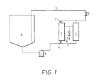
- Figure 1 shows a simple embodiment of an apparatus suitable for carrying out the process of the present invention, including the ultrafiltration cartridges (1) with their whitewater inlets (6), whitewater outlets (7) and permeate outlet (8), the whitewater inlet line (2), the pumping means (3), the whitewater source (4), the return line (11) allowing retentate to be returned to the whitewater source (4), and the control valve (12).
- Two cartridges are shown, but the invention as contemplated includes embodiments wherein only one cartridge is used, or wherein a plurality are used, in parallel as shown, in series, or in a series configuration of parallel cartridges.
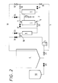
- FIG. 2 shows a preferred configuration of an apparatus for use in the present invention, wherein a pre-filter (9), preferably a bag filter or equivalent filter, is placed in the whitewater inlet line to remove large particulate matter that may foul the cartridge membranes, a recirculating line (5) is provided to allow the whitewater to recirculate from the whitewater outlet of the cartridge to the inlet of the pump and a smaller, auxiliary source (10) of whitewater is provided. Control valves (12 - 24) are also indicated which permit the apparatus to be operated in the manner described below. A bleed line (11) is also shown which allows any retentate which is bled off, to reduce pressure in the system, to be returned to the whitewater source tank.
- a pre-filter preferably a bag filter or equivalent filter
- the polymer solids With the ultrafiltration of whitewater, the polymer solids are progressivelyconcentrated, thus increasing the viscosity. This rise in viscosity reduces cross flow velocities, at a constant pressure drop across the length of the cartridge, and consequently the solute layer at the membrane wall tends to increase in size and resistance. Thus, the flux of permeate is related to the concentration of polymer solids.
- the semipermeable membranes useful in ultrafiltration may be made from a variety of materials.
- inorganic membranes such as ceramic membranes, as well as composite materials in which a ceramic membrane is supported by an organic material, or an organic membrane is supported by an inorganic structure
- preferred membranes are those made from synthetic or natural polymeric materials. These include membranes in which the porous support structure is integral to the membrane layer, and those in which the membrane layer is cast or otherwise layered onto the porous support structure.
- Particularly suitable for semipermeable membranes in our process are those synthetic polymeric materials which may be cast, spun or extruded into semipermeable membranes, and which are temperature resistant and solvent resistant.
- membrane materials include, but are not limited to, depending upon the process, polyamides, such as nylon and aromatic polyamides; polyphenylene oxides; olefinic resins, such as polypropylene, polyethylene and the like; sulfones such as polysulfone, polyethersulfone and the like; cellulosics such as cellulose acetate, cellulose nitrate, mixed cellulose acetate-nitrate and the like; and sulfonated polymers such as sulfonated polysulfone, sulfonated polyethersulfone and the like.
- polyamides such as nylon and aromatic polyamides
- polyphenylene oxides such as polypropylene, polyethylene and the like
- sulfones such as polysulfone, polyethersulfone and the like
- cellulosics such as cellulose acetate, cellulose nitrate, mixed cellulose acetate-nitrate and the like
- the selected material for the semipermeable membrane should preferably be suitable for the normal membrane-preparation processes, that is, it should be capable of being cast as a thin layer onto a suitable support material, extruded or spun into tubes, hollow fibers or other suitable structures, either from a melt or from solution in suitable solvents, or otherwise being formed into membranes.
- Copolymers made by copolymerizing two or more monomers are also among such suitable polymeric materials, for example copolymers made by copolymerizing two or more of acrylonitrile, methacrylonitrile and other ethylenically unsaturated dienes such as isoprene and butadiene, various acrylates such as acrylates and methacrylates, and other acrylic resins such as the esters of acrylic and methacrylic acids, for example methyl, ethyl, isopropyl and hexyl acrylates and methacrylates.
- suitable polymeric materials for example copolymers made by copolymerizing two or more of acrylonitrile, methacrylonitrile and other ethylenically unsaturated dienes such as isoprene and butadiene, various acrylates such as acrylates and methacrylates, and other acrylic resins such as the esters of acrylic and methacrylic acids, for example methyl, ethyl, is
- Membranes preferred in this invention are anisotropic membranes, more preferably anisotropic, hollow-fiber membranes, and still more preferably anisotropic, hollow-fiber membranes made of polysulfone.
- Anisotropic membranes have a relatively thick, support structure of large, open pores, referred to herein as the "porous support", with a thin "skin", or active membrane layer which contains the selective pores, on one side.
- the porous support structure forms the fiber itself, and the active membrane layer forms the inner surface that defines the hollow core, or lumen, of the fiber. This inner surface is also referred to herein as the "tube side" of the membrane, as opposed to the porous support side, or outer side.
- the porous support structure is typically from about 125 ⁇ m to about 550 ⁇ m thick and the active membrane layer is typically about 0.1 ⁇ m thick.
- the preferred fibers of the Examples had inside diameters (ID) of 1.52 to 1.90 mm (60 to 75 mil).
- the hollow fibers may be bundled together and secured in a cartridge, which is usually made of plastics material.
- the process fluid in this case the whitewater
- the ultrafiltered permeate as it passes through the active membrane layer and exits via the porous support structure of the fiber, is collected within the body of the cartridge, from which it is then drained as an essentially polymer-free liquid.
- the polysulfone membranes may be operated under conditions which include a pH range of 1-14, a temperature from 0°C to about 70°C, and a maximum pressure across the membrane of about 275 kPa.
- the maximum temperature the membranes can withstand is about 70°C and the maximum operating pressure is about 275 kPa.
- the membranes will not tolerate temperatures below 0°C because the moisture entrained in the polysulfone matrix will freeze and may rupture the membrane.
- the polysulfone membrane is not normally used with organic solvents, as the membrane surface may be damaged or the support structure actually dissolved by certain solvents.
- Two different types of cartridges were used in the Examples below; the PM500-75 and the PM50-60. The PM500-75 is more preferred. These cartridges were obtained from Romicon, Inc., Woburn, MA 01801. The cartridges have the following characteristics:
- Both cartridges have a diameter of 12.7-cm and a length of 1.092 meters.
- the PM500-75 cartridge contains about 790 individual polysulfone fibers and the PM50-60 cartridge contains about 1250.
- the PM500-75 cartridge showed slightly better flow characteristics than the PM50-60 cartridge.
- An ultrafiltration system consists of three major components; a source of liquid to be treated, one or more ultrafiltration membrane, and a means for moving the liquid from the source to the membrane(s) and generating a pressure differential across the membrane(s). This is usually a pump or other pumping means.
- a pump or other pumping means An example of a practical arrangement of these components of such a simple system is shown in Figure 1. This set-up is termed straight batch.
- Ancillary components which may be added to such a simple system include a pre-filter which removes from the liquid any particulate matter which is large enough to plug the constricted portions of the system, e.g. the lumens of hollow-fiber membranes where these are employed.
- FIG. 2 A more elaborate embodiment of an apparatus used in the present invention is shown in Figure 2, which illustrates the use of additional system components: the pre-filter (9) described above, a recirculation line (5) to recirculate whitewater from the whitewater outlets (7) of the cartridge(s) back to the inlet of the pump (3), an auxiliary tank (10) that may be used instead of the main feed tank as the whitewater source when the volume of the whitewater latex has been reduced significantly, and various control valves (12-24) which may be used to control the operation of the apparatus during the process of the present invention.
- the pre-filter (9) described above a recirculation line (5) to recirculate whitewater from the whitewater outlets (7) of the cartridge(s) back to the inlet of the pump (3)
- an auxiliary tank (10) that may be used instead of the main feed tank as the whitewater source when the volume of the whitewater latex has been reduced significantly
- various control valves (12-24) which may be used to control the operation of the apparatus during the process of the present invention.
- the pump must be able to circulate the process fluid at a flow high enough to maintain the desired pressure at the inlet of the cartridge, e.g. 200-275 kPa in the embodiment shown.
- a suitable pump is a horizontally mounted, centrifugal pump with a double mechanical water-flush seal, or a double-diaphragm pump such as the Wilden M-15 pump obtainable from Wilden Pump and Engineering Company, Colton, California, USA.
- This latter pump is a low-shear pump which is particularly advantageous in the process of the present invention; other pumps may be used if care is taken to maintain the low shear required for the process.
- this pump should be able to pump cleaning solution at about 415 liters per minute per cartridge at an inlet pressure of about 200 kPa to ensure adequate cleaning of the membrane.
- Some whitewater emulsions are more sensitive than others to destabilization at higher temperatures.
- the pumping of the emulsion through the ultrafiltration system adds energy to the emulsion, raising its temperature, so a cooling means in the recirculation loop may be desirable.
- One suitable cooling means would be a heat exchanger, and preferably a heat exchanger that exchanges heat between the emulsion and a flowing, cooled liquid.
- the pressure applied to the concentrated latex is preferably controlled to minimize shear of the latex and help prevent its destabilization.
- the pressure and shear tend to increase as the solids content, and consequently the latex viscosity, increase.
- One way to control the applied pressure is to control the speed of the pump; an alternative way is to bleed off excess pressure by bleeding whitewater from the pressurized portion of the system back into the whitewater source.
- a filter e.g. the prefilter (9) in the embodiment illustrated in Figure 2, placed in the whitewater flow between the whitewater source and the whitewater inlet of the cartridge, is a preferred component of an ultrafiltration system which helps protect the hollow-fiber membrane from large particles that can plug the fibers or tear the membrane.
- the filter which may be a bag filter or similar filter, is typically positioned downstream from the pump in the recirculation loop. The filter may also be placed upstream from the pump in the feed line, although an additional pump may be needed to pump the whitewater from the feed tank through the filter. This option allows the filter to operate at lower flow rates than when it is placed in the recirculation loop.
- the filter should be such that it will retain particles large enough to plug the lumens of hollow-fiber membranes, or other constricted points in the system; in a preferred embodiment the filter is a screen with a mesh size that passes particles no larger than approximately half the size of the lumen diameters. Smaller-mesh filters are less preferred because they increase pressure drop and shear.
- the holdup volume is preferably about 15% or less of the initial volume of whitewater to be concentrated, more preferably about 10% or less, and still more preferably about 5% or less.
- the whitewater source may be a tank or similar vessel, or other source of whitewater produced during cleaning of equipment for producing a particular type of polymer latex, and stored for polymer recovery.
- the source is a tank or similar vessel
- the bottom of the vessel preferably has a conical shape to facilitate maintaining a reasonable depth of latex, so that air is not drawn into the system by the pump.
- an optional, smaller vessel e.g. auxiliary tank (10) in the embodiment illustrated in Figure 2, may be employed when the volume of latex has dropped below a level practical for the larger source vessel.
- Periodically cleaning the membrane surface may increase the flux rate of permeate.
- Cleaning frequency is determined by the frequency at which the flux rate drops below a desired level, and a typical frequency is hourly.
- the desired flux rate is selected such that fouling of the membrane is still reversible; if ultrafiltration is continued significantly past the desired minimum flux rate, the fouling becomes more and more difficult to adequately remove, and if continued sufficiently past the desired minimum flux rate, the fouling becomes essentially permanent; that is, the membrane cannot be restored to a reasonable approximation of its initial flux rate even with extreme cleaning measures.
- Increased difficulty in removing fouling increases the time required for cleaning, and thus the time the membrane is out of service.
- a preferred value for the desired minimum flux rate is about 10% to 15% of the initial whitewater flux rate.
- Reverse flow/recycle is a combination of permeate recycling and reversing the direction of process-fluid flow.
- the permeate flow from the cartridge is blocked, and the pressure outside the membrane fibers is allowed to rise until it is approximately equal to the average pressure inside the fiber lumens from inlet to outlet.
- the pressure is reversed across the membrane over at least a portion of the length of the membrane; that is, a reverse pressure differential is established across at least a portion of the membrane.
- the permeate flows from the porous support side of the membrane fibers to the tube side in the exit (lower pressure) portion of the fibers, where the reverse pressure differential is established, and from the tube side to the porous support side in the inlet (high pressure) portion of the fibers, where the pressure differential is in the normal direction, that is, the same direction as when the whitewater is being treated.
- the reversed flow of the permeate i.e., from the porous support side to the tube side of the membrane, cleans the inner surface of the fibers.
- This flow reversal occurs for a pre-defined time, during which automated valves also reverse the flow of the process fluid (whitewater) through the fibers.
- the flow direction is opposite of the direction that it started and both ends of the cartridge have been cleaned by permeate recycle.
- Vacuum-flush cleaning is similar to reverse flow/recycle in that it involves the flow of permeate from the porous support side to the tube side of the hollow fibers. This feature is possible with high pressure bleed systems. With the pump operating, automated valves alter the flow patterns to create a negative pressure in the recirculation loop, which forces the permeate, at atmospheric pressure, back through the porous support side to the tube side, cleaning the membrane surface. Note that recirculation flow across the membrane surface ceases during this cleaning process. This process is also called “suction backwashing", and is described in, for example, US-A-4,986,918.
- Backflushing is similar to vacuum-flush cleaning except that the permeate is forced, usually by a small pump, back through the porous support side into the tube side of the hollow fiber.
- the process fluid may continue to recirculate through the cartridges.
- the ultrafiltration unit should be cleaned frequently to maintain reasonable flux rates. In batch operations, cleaning after every batch is typical, while with continuous systems a reasonable compromise between flux rate and unit down-time must be selected. Cleaning after batches also helps prevent cross-contamination of different products.
- a cleaning solution useful for cleaning polymeric membranes of the present invention is 1% by weight of sodium hydroxide and 200 ppm by weight of sodium hypochlorite in deionized water.
- Surfactants may be used separately, or with a cleaning solution such as that described above.
- a preferred cleaning solution is sold under the trademark, Micro, made by International Products Corp., Burlington, NJ.
- Glycine N,N'-1,2-ethanediylbis-(N-(carboxymethyl))-, tetrasodium salt
- Benzenesulfonic acid dimethyl-, ammonium salt
- Benzenesulfonic acid docecyl-, cpd with 2,2',2''-nitrilotris-(ethanol)
- Poly(oxy-1,2-ethanediyl), a-(nonylphenyl)- ⁇ -hydroxy Typical cleaning temperatures are elevated to the range of 40-60°C to increase the cleaning rate of the solution, and typical cleaning times are about 30 to 60 minutes.
- the deionized water is used to prevent metal ions from fouling the membrane over long period of time.
- the product designations in Table 1 indicate products of Rohm and Haas Company, Philadelphia, PA 19105. Those marked with 1 are Rhoplex products and those marked with 2 are Polyco products. Rhoplex and Polyco are trademarks of Rohm and Haas Company.
- polymer latices represent a wide variety of latex products, incorporating a variety of surfactants, including anionic, nonionic and cationic surfactants.
- surfactants including anionic, nonionic and cationic surfactants.
- polymer can be recovered from the whitewater generated during cleanup of equipment used for manufacturing each of these latices, and the recovered polymer has properties that are close enough to the original polymer latex product that the recovered polymer may be blended into the polymer latex product without degrading the performance characteristics of the product in the intended applications.
- a drain tank rinse (whitewater) was pumped from a plant drain tank by a Wilden diaphragm pump (obtained from Wilden Pump and Engineering Company, Colton, California USA), through an 800- ⁇ m strainer into a 1325-liter tote which was then stored until ultrafiltration.
- Wilden diaphragm pump obtained from Wilden Pump and Engineering Company, Colton, California USA
- Whitewater from drain-tank flushes was prefiltered through an 800- ⁇ m bag filter or a Johnson sock filter as the whitewater was pumped from the tote to the feed tank by a diaphragm pump, to filter out any polymer skin or gel which may have formed on the liquid surface when the totes were stored.
- the pilot unit consisted of a 4550-liter feed tank, a 380-liter auxiliary feed tank and a two-cartridge, skid-mounted ultrafiltration unit.
- the main components of the ultrafiltration unit were the following: Horizontally mounted centrifugal pump with a double mechanical water-flush seal, rated for 7460 joule/second (10 horsepower) at 1750 RPM, capable of pumping 530 liters/minute against a 270 kPa head. Speed control for the pump.
- Bag filter positioned after the pump in the recirculation loop. Two 1.09-meter-long, 12.7-cm-diameter membrane cartridges. Recirculation loop with option of:
- the auxiliary feed tank was used at the end of a run to avoid turbulence and splashing which occurred in the 4550-liter feed tank when the volume was smaller than 380 liters.
- the bag filter was located in the recirculation loop between the pump and the membrane cartridges. With dilute whitewater, a filtration rate of 760 liters/minute could be maintained. When 200 ⁇ m and 400 ⁇ m filter bags were used, they fouled badly, dropping the cartridge inlet pressure below 140 kPa; using 800 ⁇ m bags avoided this fouling.
- the PM500-75 membrane was preferred for ultrafiltering whitewater because it allows higher cross-flow at higher whitewater viscosity than the smaller PM50-60 membrane.
- the unit was flooded with water, trapped air was bled off, and the pump speed was increased until the desired cartridge inlet pressure was reached.
- the inlet and outlet cartridge pressure was maintained at 210 kPa and 35 kPa, respectively. At high solids levels, greater than 30 weight percent, the viscosity increased rapidly, which increased the inlet pressure on the cartridges and the pressure drop through the cartridge.
- the pump speed was controlled to maintain the inlet pressure at 200-240 kPa.
- the outlet pressure was controlled with valves in the recirculation loop and the low pressure bleed line.
- the system was either left at a manual setting, without any maintenance cleaning, or set to automatic, with the reverse flow/recycle and/or the vacuum-flush cleaning feature activated.
- the system pump was turned off and the unit was drained and sampled for blending and lab analysis.
- the automated reverse-flow valves were activated and the system was shut off with the valves in their half-way positions to allow complete drainage.
- the system After the system had completely drained of concentrated whitewater, it was set to its cleaning mode and flushed with water, or with the permeate that had collected in the cleaning tank during processing. In the cleaning mode, the system feeds from the built-in cleaning tank, thus segregating the whitewater feed tank from the unit. The unit was flushed for a total of 5 to 10 minutes, then drained as with the concentrated whitewater.
- the unit was cleaned with an aqueous, 1% sodium hydroxide solution, optionally with a small amount of Micro cleaning solution (described above), prepared using deionized water, at 30-60°C.
- an aqueous, 1% sodium hydroxide solution optionally with a small amount of Micro cleaning solution (described above), prepared using deionized water, at 30-60°C.
- the inlet and outlet cartridge pressures were the same as with normal processing, 210 and 35 kPa, respectively.
- the permeate valves were closed to place the cartridges in recycle, and the unit could be set to manual or automatic mode. In automatic mode the flow direction reversed every 15 minutes.
- the unit was flushed with tap water, and tap water was circulated through the system at the same operating pressure as in normal processing, but with the cartridges set to recycle.
- Table 3 shows that the wide range of whitewater emulsions described in Table 1 may be ultrafiltered according to the process of the present invention, at practical flow rates.
- the average flux value is determined, using a modification of the above-described procedure in which only one cartridge is used, by averaging the flux through one of five PM500-75 cartridges (described above) over the solids range from 4% to 30%.
- Flux 1182 ⁇ 650 liters/m 2 /day 6 4 1140 4 733 Other 5 1222 19 1 1670 1 1018 2 1508 2 896 15 4 570 7 4 978 16 4 693 5 1548 5 774 Avg.
- Example 10 the recovered material of Example 10 was tested at similar blend levels for gloss, brightness, opacity and surface pick strength in standard paper-performance testing; no adverse effect was seen.
- Example 11 the recovered material of Example 11 was tested at similar blend levels for wash durability by spraying the polymer latex onto a polyester web and laundering it under household laundry conditions for five cycles; no adverse effect on durability was seen.
- Example 12 was tested at similar blend levels for tensile strength and stretch on a simulated "wet-wipe" non-woven fabric. Another test of tensile strength that involved soaking the fabric in a simulant for the consumer lotion used with wet wipes and comparing the results after a 1-hour soak and after soaking at 49°C for 10 days was run using the material of Example 12 at the 1% and 5% blend levels; no adverse effect on any of these properties was seen.
- Example 16 the recovered material of Example 16 was tested at similar blend levels for floor-polish properties; no adverse effect was seen.
- the recovered materials of Examples 1, 3, 4, 6 and 7 were tested at similar blend levels as emulsions for the following properties: freeze-thaw stability by exposing to 5 cycles of freezing and thawing; heat aging, by heating to 60°C and holding at that temperature for 10 days; and mechanical stability, by agitating in a Waring Blendor ("Waring” and "Blendor” are trademarks of Dynamics Corporation of America, New York, NY, USA) mixer for five minutes at high speed.
- Waring Blendor Waring" and "Blendor” are trademarks of Dynamics Corporation of America, New York, NY, USA
- These same materials were blended into standard paint formulations and tested for gloss, adhesion, color acceptance and the freeze-thaw stability and heat ageing described above. Except for the color acceptance tests for the materials of Examples 1 and 6, for which no data are available, no adverse effect was seen on any of these properties for any of these materials as recovered emulsions or as paints formulated from the recovered emulsions.
- the polymer latex recovered by the process of the present invention is capable of being blended into undiluted polymer latex at significant levels without deleteriously affecting the important properties of the undiluted latex.
- Such a capability means that the polymer in the whitewater emulsion, which heretofore has represented only waste to be disposed of, or a low-grade byproduct, may now be returned to the product stream, significantly increasing the yield of the process and significantly reducing the environmental problem of waste disposal.
Landscapes
- Chemical & Material Sciences (AREA)
- Chemical Kinetics & Catalysis (AREA)
- Organic Chemistry (AREA)
- Health & Medical Sciences (AREA)
- Medicinal Chemistry (AREA)
- Polymers & Plastics (AREA)
- Engineering & Computer Science (AREA)
- Water Supply & Treatment (AREA)
- Sustainable Development (AREA)
- Life Sciences & Earth Sciences (AREA)
- Separation Using Semi-Permeable Membranes (AREA)
- Processes Of Treating Macromolecular Substances (AREA)
- Separation, Recovery Or Treatment Of Waste Materials Containing Plastics (AREA)
- Addition Polymer Or Copolymer, Post-Treatments, Or Chemical Modifications (AREA)
- Compositions Of Macromolecular Compounds (AREA)
- Graft Or Block Polymers (AREA)
- Paints Or Removers (AREA)
- Compounds Of Unknown Constitution (AREA)
- External Artificial Organs (AREA)
Applications Claiming Priority (2)
| Application Number | Priority Date | Filing Date | Title |
|---|---|---|---|
| US07/695,863 US5171767A (en) | 1991-05-06 | 1991-05-06 | Utrafiltration process for the recovery of polymeric latices from whitewater |
| US695863 | 1991-05-06 |
Publications (3)
| Publication Number | Publication Date |
|---|---|
| EP0512736A2 EP0512736A2 (en) | 1992-11-11 |
| EP0512736A3 EP0512736A3 (en) | 1993-01-13 |
| EP0512736B1 true EP0512736B1 (en) | 1998-07-15 |
Family
ID=24794749
Family Applications (1)
| Application Number | Title | Priority Date | Filing Date |
|---|---|---|---|
| EP92303831A Revoked EP0512736B1 (en) | 1991-05-06 | 1992-04-28 | Ultrafiltration processes for the recovery of polymeric latices from whitewater, and apparatus therefor |
Country Status (20)
| Country | Link |
|---|---|
| US (3) | US5171767A (OSRAM) |
| EP (1) | EP0512736B1 (OSRAM) |
| JP (1) | JP3276085B2 (OSRAM) |
| KR (1) | KR100248184B1 (OSRAM) |
| CN (1) | CN1035746C (OSRAM) |
| AT (1) | ATE168385T1 (OSRAM) |
| AU (1) | AU655461B2 (OSRAM) |
| BR (1) | BR9201680A (OSRAM) |
| CA (1) | CA2067283A1 (OSRAM) |
| CS (1) | CS137492A3 (OSRAM) |
| DE (1) | DE69226218T2 (OSRAM) |
| DK (1) | DK0512736T3 (OSRAM) |
| FI (1) | FI922023A7 (OSRAM) |
| HU (1) | HUT63866A (OSRAM) |
| IL (1) | IL101674A0 (OSRAM) |
| MY (1) | MY107757A (OSRAM) |
| NO (1) | NO921633L (OSRAM) |
| NZ (1) | NZ242462A (OSRAM) |
| PL (1) | PL294450A1 (OSRAM) |
| TW (1) | TW203563B (OSRAM) |
Cited By (1)
| Publication number | Priority date | Publication date | Assignee | Title |
|---|---|---|---|---|
| US8648131B2 (en) | 2008-07-07 | 2014-02-11 | Kraton Polymers U.S. Llc | Process for the preparation of an artificial latex |
Families Citing this family (49)
| Publication number | Priority date | Publication date | Assignee | Title |
|---|---|---|---|---|
| DE4140086C2 (de) * | 1991-12-05 | 1994-08-25 | Basf Ag | Verfahren zur Herstellung hochreiner N-Vinylpyrrolidon-Polymerisate |
| CH687055A5 (de) * | 1993-12-03 | 1996-09-13 | Bucher Guyer Ag Masch | Verfahren und Vorrichtung zum Eindicken von Fest/Fluessig-Gemischen mittels Membrantechnologie. |
| GB9316740D0 (en) * | 1993-08-12 | 1993-09-29 | North West Water Group Plc | Process for treating latex-containing waste water |
| JPH07112185A (ja) * | 1993-08-26 | 1995-05-02 | Nitto Denko Corp | 排水処理装置およびその洗浄方法 |
| US5811224A (en) * | 1994-08-24 | 1998-09-22 | Bayer Corporation | Process for rejuvenating developer in printing plate development |
| IT1275427B (it) * | 1995-05-16 | 1997-08-07 | Bracco Spa | Processo per la depirogenazione di soluzioni farmaceutiche iniettabili |
| US6359114B1 (en) * | 1995-06-07 | 2002-03-19 | Aphton Corp. | System for method for the modification and purification of proteins |
| JPH11509010A (ja) * | 1995-07-13 | 1999-08-03 | ポリフアイブロン・テクノロジーズ・インコーポレーテツド | フォトポリマー印刷版の作製 |
| JPH11129629A (ja) * | 1997-10-27 | 1999-05-18 | Fuji Photo Film Co Ltd | 記録材料およびその製造方法 |
| US6027853A (en) * | 1998-01-16 | 2000-02-22 | Olin Microelectronic Chemicals, Inc. | Process for preparing a radiation-sensitive composition |
| US6019902A (en) * | 1998-04-03 | 2000-02-01 | Durr Environmental, Inc. | Fluid recovery system |
| NL1009218C2 (nl) * | 1998-05-20 | 1999-11-24 | Akzo Nobel Nv | Bereiding van een polymeer onder toepassing van een anorganisch membraan met een kleine gemiddelde poriegrootte. |
| US6075073A (en) * | 1998-08-20 | 2000-06-13 | Apex Medical Technologies, Inc. | Latices from emulsified hydrocarbon rubber solutions by membrane separation |
| GB9820935D0 (en) * | 1998-09-25 | 1998-11-18 | Pall Corp | Filtration system |
| AU3935700A (en) | 1999-06-21 | 2001-01-04 | Rohm And Haas Company | Ultrafiltration processes for the recovery of polymeric latices from whitewater |
| US6755970B1 (en) * | 1999-06-22 | 2004-06-29 | Trisep Corporation | Back-flushable spiral wound filter and methods of making and using same |
| CN1245249C (zh) * | 2001-09-18 | 2006-03-15 | 天津膜天膜工程技术有限公司 | 中空纤维膜分离装置及其运行方法 |
| US7892993B2 (en) | 2003-06-19 | 2011-02-22 | Eastman Chemical Company | Water-dispersible and multicomponent fibers from sulfopolyesters |
| US20040260034A1 (en) | 2003-06-19 | 2004-12-23 | Haile William Alston | Water-dispersible fibers and fibrous articles |
| US7687143B2 (en) | 2003-06-19 | 2010-03-30 | Eastman Chemical Company | Water-dispersible and multicomponent fibers from sulfopolyesters |
| US8513147B2 (en) | 2003-06-19 | 2013-08-20 | Eastman Chemical Company | Nonwovens produced from multicomponent fibers |
| US7179376B2 (en) * | 2003-11-24 | 2007-02-20 | Ppg Industries Ohio, Inc. | Method and system for removing residual water from excess washcoat by ultrafiltration |
| DE102004055542A1 (de) * | 2004-11-17 | 2006-05-18 | Basf Ag | Verfahren zur Herstellung einer feinteiligen Emulsion aus einer Rohemulsion |
| FI20051121A7 (fi) | 2005-11-04 | 2007-05-05 | Oy Keskuslaboratorio Centrallaboratorium Ab | Menetelmä ja laite kiintoainepitoisten vesisuspensioiden suodattamiseksi |
| US7635745B2 (en) | 2006-01-31 | 2009-12-22 | Eastman Chemical Company | Sulfopolyester recovery |
| JP2007252966A (ja) | 2006-03-20 | 2007-10-04 | Toshiba Corp | 膜モジュールおよび水処理システム |
| US20100140465A1 (en) * | 2006-03-29 | 2010-06-10 | Chulso Moon | Apparatus and Method for Filtration to Enhance the Detection of Peaks |
| ES2340433T3 (es) | 2006-06-26 | 2010-06-02 | Basf Se | Procedimiento para la obtencion de una dispersion acuosa de polimeros. |
| KR100782545B1 (ko) * | 2006-07-12 | 2007-12-06 | (주)우리텍 | 라텍스 용액의 농축을 위한 나노 멤브레인 모듈 |
| KR100735713B1 (ko) | 2006-07-12 | 2007-07-06 | (주)우리텍 | 나노 멤브레인 모듈을 이용한 라텍스용액 농축 장치 |
| KR100887113B1 (ko) * | 2006-09-14 | 2009-03-04 | 주식회사 엘지화학 | 분리막을 이용한 고분자 라텍스 분체의 제조방법 |
| DE202006014582U1 (de) * | 2006-09-20 | 2006-12-14 | Technotrans Ag | Vorrichtung zur Reinigung des Feuchtmittels für den Offset-Druck |
| US8355898B2 (en) | 2008-06-17 | 2013-01-15 | Chevron U.S.A. Inc. | System and method for modeling flow events responsible for the formation of a geological reservoir |
| US8597563B2 (en) * | 2008-07-11 | 2013-12-03 | Rohm And Haas Company | Recycled thermoplastic composition comprising waste thermoset material and methods of making |
| US9238586B2 (en) * | 2008-11-20 | 2016-01-19 | Alion Science & Technology | Filter cleaning method |
| US8512519B2 (en) | 2009-04-24 | 2013-08-20 | Eastman Chemical Company | Sulfopolyesters for paper strength and process |
| GB201000160D0 (en) * | 2010-01-07 | 2010-02-24 | Gas2 Ltd | Apparatus for adiabatic methane conversion |
| US20110196138A1 (en) * | 2010-02-11 | 2011-08-11 | Mafco Worldwide Corporation | Separation of glycyrrhizic acid from licorice extract by ultrafiltration |
| US9273417B2 (en) | 2010-10-21 | 2016-03-01 | Eastman Chemical Company | Wet-Laid process to produce a bound nonwoven article |
| US8882963B2 (en) | 2012-01-31 | 2014-11-11 | Eastman Chemical Company | Processes to produce short cut microfibers |
| JP5941995B2 (ja) * | 2012-11-28 | 2016-06-29 | 株式会社クラレ | クーラント再生方法、及びクーラント再生装置 |
| US9617685B2 (en) | 2013-04-19 | 2017-04-11 | Eastman Chemical Company | Process for making paper and nonwoven articles comprising synthetic microfiber binders |
| US9605126B2 (en) | 2013-12-17 | 2017-03-28 | Eastman Chemical Company | Ultrafiltration process for the recovery of concentrated sulfopolyester dispersion |
| US9598802B2 (en) | 2013-12-17 | 2017-03-21 | Eastman Chemical Company | Ultrafiltration process for producing a sulfopolyester concentrate |
| US10144688B2 (en) * | 2016-03-17 | 2018-12-04 | Aéro Mag 2000 Rrr Inc. | Method and system for recycling spent ethylene glycol from recovered aircraft de-icing solutions |
| CN106957087A (zh) * | 2017-03-06 | 2017-07-18 | 佛山市亿达胶粘制品有限公司 | 一种粘胶剂生产废料的处理方法 |
| CN111499026A (zh) * | 2020-05-29 | 2020-08-07 | 涧纳(上海)环保科技有限公司 | 一种稀丙烯酸乳液的回收装置及处理方法 |
| JP2024514468A (ja) | 2021-04-16 | 2024-04-02 | レプリゲン・コーポレーション | ろ過システム及び方法 |
| WO2024081574A1 (en) * | 2022-10-10 | 2024-04-18 | Repligen Corporation | Filtration systems and methods |
Family Cites Families (9)
| Publication number | Priority date | Publication date | Assignee | Title |
|---|---|---|---|---|
| US3956114A (en) * | 1973-08-31 | 1976-05-11 | Abcor, Inc. | Process for the concentration of polyvinyl-chloride emulsion |
| US4080289A (en) * | 1975-02-28 | 1978-03-21 | Hitachi, Ltd. And Hitachi Plant Engineering And Construction Co., Ltd. | Apparatus for treating waste water or solution |
| US4160726A (en) * | 1976-05-07 | 1979-07-10 | Abcor, Inc. | Ultrafiltration process for the concentration of polymeric latices |
| DE2908001C2 (de) * | 1979-03-01 | 1981-02-19 | Hoechst Ag, 6000 Frankfurt | Verfahren zur Herstellung konzentrierter Dispersionen von Fluorpolymeren |
| US4526914A (en) * | 1983-12-15 | 1985-07-02 | Manville Service Corporation | Whitewater formulation containing a cationic polyacrylamide |
| US4888115A (en) * | 1983-12-29 | 1989-12-19 | Cuno, Incorporated | Cross-flow filtration |
| US4678477A (en) * | 1986-01-06 | 1987-07-07 | Aluminum Company Of America | Process for lowering level of contaminants in Bayer liquor by membrane filtration |
| US4986917A (en) | 1989-07-10 | 1991-01-22 | First Chemical Corporation | Selective recovery of a nitrophenolic by-product from nitration waste water by extraction |
| US4986918A (en) * | 1989-11-08 | 1991-01-22 | Romicon Inc. | Membrane separation system and method of operation |
-
1991
- 1991-05-06 US US07/695,863 patent/US5171767A/en not_active Expired - Fee Related
-
1992
- 1992-04-22 IL IL101674A patent/IL101674A0/xx unknown
- 1992-04-23 MY MYPI92000694A patent/MY107757A/en unknown
- 1992-04-23 NZ NZ242462A patent/NZ242462A/en unknown
- 1992-04-27 CA CA002067283A patent/CA2067283A1/en not_active Abandoned
- 1992-04-28 AU AU15193/92A patent/AU655461B2/en not_active Ceased
- 1992-04-28 EP EP92303831A patent/EP0512736B1/en not_active Revoked
- 1992-04-28 DE DE69226218T patent/DE69226218T2/de not_active Expired - Fee Related
- 1992-04-28 AT AT92303831T patent/ATE168385T1/de active
- 1992-04-28 DK DK92303831T patent/DK0512736T3/da active
- 1992-04-28 NO NO92921633A patent/NO921633L/no unknown
- 1992-05-04 KR KR1019920007571A patent/KR100248184B1/ko not_active Expired - Fee Related
- 1992-05-05 BR BR929201680A patent/BR9201680A/pt not_active IP Right Cessation
- 1992-05-05 FI FI922023A patent/FI922023A7/fi not_active Application Discontinuation
- 1992-05-06 CS CS921374A patent/CS137492A3/cs unknown
- 1992-05-06 HU HU9201520A patent/HUT63866A/hu unknown
- 1992-05-06 CN CN92104394A patent/CN1035746C/zh not_active Expired - Fee Related
- 1992-05-06 JP JP11378292A patent/JP3276085B2/ja not_active Expired - Fee Related
- 1992-05-06 PL PL29445092A patent/PL294450A1/xx unknown
- 1992-06-03 TW TW081104364A patent/TW203563B/zh active
- 1992-07-15 US US07/914,288 patent/US5342863A/en not_active Expired - Fee Related
-
1994
- 1994-04-13 US US08/227,158 patent/US6248809B1/en not_active Expired - Fee Related
Cited By (1)
| Publication number | Priority date | Publication date | Assignee | Title |
|---|---|---|---|---|
| US8648131B2 (en) | 2008-07-07 | 2014-02-11 | Kraton Polymers U.S. Llc | Process for the preparation of an artificial latex |
Also Published As
| Publication number | Publication date |
|---|---|
| DK0512736T3 (da) | 1999-04-19 |
| CN1070353A (zh) | 1993-03-31 |
| NZ242462A (en) | 1994-04-27 |
| EP0512736A2 (en) | 1992-11-11 |
| HUT63866A (en) | 1993-10-28 |
| US6248809B1 (en) | 2001-06-19 |
| JP3276085B2 (ja) | 2002-04-22 |
| FI922023L (fi) | 1992-11-07 |
| CS137492A3 (en) | 1992-11-18 |
| IL101674A0 (en) | 1992-12-30 |
| BR9201680A (pt) | 1992-12-15 |
| DE69226218T2 (de) | 1999-03-25 |
| TW203563B (OSRAM) | 1993-04-11 |
| JPH05131119A (ja) | 1993-05-28 |
| NO921633L (no) | 1992-11-09 |
| US5342863A (en) | 1994-08-30 |
| CA2067283A1 (en) | 1992-11-07 |
| AU655461B2 (en) | 1994-12-22 |
| NO921633D0 (no) | 1992-04-28 |
| US5171767A (en) | 1992-12-15 |
| FI922023A7 (fi) | 1992-11-07 |
| KR100248184B1 (ko) | 2000-03-15 |
| PL294450A1 (en) | 1993-01-25 |
| HU9201520D0 (en) | 1992-08-28 |
| FI922023A0 (fi) | 1992-05-05 |
| MY107757A (en) | 1996-06-15 |
| ATE168385T1 (de) | 1998-08-15 |
| AU1519392A (en) | 1992-11-12 |
| CN1035746C (zh) | 1997-09-03 |
| DE69226218D1 (de) | 1998-08-20 |
| EP0512736A3 (en) | 1993-01-13 |
| KR920021590A (ko) | 1992-12-18 |
Similar Documents
| Publication | Publication Date | Title |
|---|---|---|
| EP0512736B1 (en) | Ultrafiltration processes for the recovery of polymeric latices from whitewater, and apparatus therefor | |
| US5690830A (en) | Waste water treatment apparatus and washing method thereof | |
| AU563321B2 (en) | Cleaning of filters | |
| US6417251B1 (en) | Ultrafiltration processes for the recovery of polymeric latices from whitewater | |
| JPH088980B2 (ja) | フィルタの洗浄 | |
| EP0160014A1 (en) | CLEANING THE FILTERS. | |
| US20080271758A1 (en) | Method of cleaning fouled and/or scaled membranes | |
| JPH07236818A (ja) | 内圧式中空糸モジュールの逆洗方法 | |
| JPH0669530B2 (ja) | クロスフロ−濾過システムの流束率を向上せしめる方法並びに装置 | |
| US5964231A (en) | Systems for purging process lines of additives for thermoplastic materials | |
| CN1317056C (zh) | 中空纤维膜滤装置的冲洗方法 | |
| IE921448A1 (en) | Ultrafiltration processes for the recovery of polymeric¹latices from whitewater, and apparatus therefor | |
| KR840000470B1 (ko) | 에멀젼중합에 있어서 비닐수지 유액의 한외여과와 침투물의 재사용 | |
| JP3601015B2 (ja) | 膜を用いた濾過方法 | |
| JPS6382B2 (OSRAM) | ||
| Buckley et al. | Fouling studies and mathematical modelling of ultrafiltration of textile desizing effluents | |
| JPH02284609A (ja) | セラミックフィルタの運転方法 | |
| JPH09122451A (ja) | 中空糸膜モジュールを用いるろ過装置及びその運転方法 | |
| JPH11197471A (ja) | 膜分離装置の洗浄方法 |
Legal Events
| Date | Code | Title | Description |
|---|---|---|---|
| PUAI | Public reference made under article 153(3) epc to a published international application that has entered the european phase |
Free format text: ORIGINAL CODE: 0009012 |
|
| 17P | Request for examination filed |
Effective date: 19920515 |
|
| AK | Designated contracting states |
Kind code of ref document: A2 Designated state(s): AT BE CH DE DK ES FR GB GR IT LI LU MC NL PT SE |
|
| PUAL | Search report despatched |
Free format text: ORIGINAL CODE: 0009013 |
|
| AK | Designated contracting states |
Kind code of ref document: A3 Designated state(s): AT BE CH DE DK ES FR GB GR IT LI LU MC NL PT SE |
|
| 17Q | First examination report despatched |
Effective date: 19941229 |
|
| GRAG | Despatch of communication of intention to grant |
Free format text: ORIGINAL CODE: EPIDOS AGRA |
|
| GRAG | Despatch of communication of intention to grant |
Free format text: ORIGINAL CODE: EPIDOS AGRA |
|
| GRAH | Despatch of communication of intention to grant a patent |
Free format text: ORIGINAL CODE: EPIDOS IGRA |
|
| GRAH | Despatch of communication of intention to grant a patent |
Free format text: ORIGINAL CODE: EPIDOS IGRA |
|
| GRAA | (expected) grant |
Free format text: ORIGINAL CODE: 0009210 |
|
| AK | Designated contracting states |
Kind code of ref document: B1 Designated state(s): AT BE CH DE DK ES FR GB GR IT LI LU MC NL PT SE |
|
| PG25 | Lapsed in a contracting state [announced via postgrant information from national office to epo] |
Ref country code: GR Free format text: LAPSE BECAUSE OF NON-PAYMENT OF DUE FEES Effective date: 19980715 Ref country code: ES Free format text: THE PATENT HAS BEEN ANNULLED BY A DECISION OF A NATIONAL AUTHORITY Effective date: 19980715 Ref country code: AT Free format text: LAPSE BECAUSE OF FAILURE TO SUBMIT A TRANSLATION OF THE DESCRIPTION OR TO PAY THE FEE WITHIN THE PRESCRIBED TIME-LIMIT Effective date: 19980715 |
|
| REF | Corresponds to: |
Ref document number: 168385 Country of ref document: AT Date of ref document: 19980815 Kind code of ref document: T |
|
| REG | Reference to a national code |
Ref country code: CH Ref legal event code: NV Representative=s name: ARDIN & CIE S.A. Ref country code: CH Ref legal event code: EP |
|
| ITF | It: translation for a ep patent filed | ||
| REF | Corresponds to: |
Ref document number: 69226218 Country of ref document: DE Date of ref document: 19980820 |
|
| PG25 | Lapsed in a contracting state [announced via postgrant information from national office to epo] |
Ref country code: PT Free format text: LAPSE BECAUSE OF FAILURE TO SUBMIT A TRANSLATION OF THE DESCRIPTION OR TO PAY THE FEE WITHIN THE PRESCRIBED TIME-LIMIT Effective date: 19981015 |
|
| ET | Fr: translation filed | ||
| PLBQ | Unpublished change to opponent data |
Free format text: ORIGINAL CODE: EPIDOS OPPO |
|
| PLBI | Opposition filed |
Free format text: ORIGINAL CODE: 0009260 |
|
| REG | Reference to a national code |
Ref country code: DK Ref legal event code: T3 |
|
| PLBI | Opposition filed |
Free format text: ORIGINAL CODE: 0009260 |
|
| PG25 | Lapsed in a contracting state [announced via postgrant information from national office to epo] |
Ref country code: LU Free format text: LAPSE BECAUSE OF NON-PAYMENT OF DUE FEES Effective date: 19990428 |
|
| PG25 | Lapsed in a contracting state [announced via postgrant information from national office to epo] |
Ref country code: SE Free format text: LAPSE BECAUSE OF NON-PAYMENT OF DUE FEES Effective date: 19990429 |
|
| PG25 | Lapsed in a contracting state [announced via postgrant information from national office to epo] |
Ref country code: LI Free format text: LAPSE BECAUSE OF NON-PAYMENT OF DUE FEES Effective date: 19990430 Ref country code: DK Free format text: LAPSE BECAUSE OF NON-PAYMENT OF DUE FEES Effective date: 19990430 Ref country code: CH Free format text: LAPSE BECAUSE OF NON-PAYMENT OF DUE FEES Effective date: 19990430 |
|
| PLBF | Reply of patent proprietor to notice(s) of opposition |
Free format text: ORIGINAL CODE: EPIDOS OBSO |
|
| 26 | Opposition filed |
Opponent name: BASF AKTIENGESELLSCHAFT, LUDWIGSHAFEN Effective date: 19990413 |
|
| 26 | Opposition filed |
Opponent name: DEGUSSA-HUELS AG PATENTE UND MARKEN Effective date: 19990415 Opponent name: BASF AKTIENGESELLSCHAFT, LUDWIGSHAFEN Effective date: 19990413 |
|
| PLBF | Reply of patent proprietor to notice(s) of opposition |
Free format text: ORIGINAL CODE: EPIDOS OBSO |
|
| NLR1 | Nl: opposition has been filed with the epo |
Opponent name: DEGUSSA-HUELS AG PATENTE UND MARKEN Opponent name: BASF AKTIENGESELLSCHAFT, LUDWIGSHAFEN |
|
| PG25 | Lapsed in a contracting state [announced via postgrant information from national office to epo] |
Ref country code: MC Free format text: LAPSE BECAUSE OF NON-PAYMENT OF DUE FEES Effective date: 19991031 |
|
| PLBF | Reply of patent proprietor to notice(s) of opposition |
Free format text: ORIGINAL CODE: EPIDOS OBSO |
|
| REG | Reference to a national code |
Ref country code: CH Ref legal event code: PL |
|
| EUG | Se: european patent has lapsed |
Ref document number: 92303831.9 |
|
| PLBF | Reply of patent proprietor to notice(s) of opposition |
Free format text: ORIGINAL CODE: EPIDOS OBSO |
|
| REG | Reference to a national code |
Ref country code: DK Ref legal event code: EBP |
|
| REG | Reference to a national code |
Ref country code: GB Ref legal event code: IF02 |
|
| PGFP | Annual fee paid to national office [announced via postgrant information from national office to epo] |
Ref country code: FR Payment date: 20020311 Year of fee payment: 11 |
|
| PGFP | Annual fee paid to national office [announced via postgrant information from national office to epo] |
Ref country code: GB Payment date: 20020313 Year of fee payment: 11 |
|
| PGFP | Annual fee paid to national office [announced via postgrant information from national office to epo] |
Ref country code: DE Payment date: 20020314 Year of fee payment: 11 |
|
| PGFP | Annual fee paid to national office [announced via postgrant information from national office to epo] |
Ref country code: NL Payment date: 20020318 Year of fee payment: 11 |
|
| PGFP | Annual fee paid to national office [announced via postgrant information from national office to epo] |
Ref country code: BE Payment date: 20020417 Year of fee payment: 11 |
|
| RDAH | Patent revoked |
Free format text: ORIGINAL CODE: EPIDOS REVO |
|
| RDAG | Patent revoked |
Free format text: ORIGINAL CODE: 0009271 |
|
| STAA | Information on the status of an ep patent application or granted ep patent |
Free format text: STATUS: PATENT REVOKED |
|
| 27W | Patent revoked |
Effective date: 20011215 |
|
| GBPR | Gb: patent revoked under art. 102 of the ep convention designating the uk as contracting state |
Free format text: 20011215 |
|
| NLR2 | Nl: decision of opposition |
Effective date: 20011215 |