EP0512224B1 - Hand stamp with self-inking unit - Google Patents
Hand stamp with self-inking unit Download PDFInfo
- Publication number
- EP0512224B1 EP0512224B1 EP92104639A EP92104639A EP0512224B1 EP 0512224 B1 EP0512224 B1 EP 0512224B1 EP 92104639 A EP92104639 A EP 92104639A EP 92104639 A EP92104639 A EP 92104639A EP 0512224 B1 EP0512224 B1 EP 0512224B1
- Authority
- EP
- European Patent Office
- Prior art keywords
- cover
- stamp
- housing
- self
- hand stamp
- Prior art date
- Legal status (The legal status is an assumption and is not a legal conclusion. Google has not performed a legal analysis and makes no representation as to the accuracy of the status listed.)
- Expired - Lifetime
Links
Images


Classifications
-
- B—PERFORMING OPERATIONS; TRANSPORTING
- B41—PRINTING; LINING MACHINES; TYPEWRITERS; STAMPS
- B41K—STAMPS; STAMPING OR NUMBERING APPARATUS OR DEVICES
- B41K1/00—Portable hand-operated devices without means for supporting or locating the articles to be stamped, i.e. hand stamps; Inking devices or other accessories therefor
- B41K1/36—Details
- B41K1/38—Inking devices; Stamping surfaces
- B41K1/40—Inking devices operated by stamping movement
- B41K1/42—Inking devices operated by stamping movement with pads or rollers movable for inking
Definitions
- the invention relates to a hand stamp apparatus with on supporting elements, e.g. Print wheels arranged printing marks, which are wettable by a self-inking element with printing ink, in particular during their upward movement following their depression, at least one rest position of the printing characters, in which the self-inking element is held at a distance from them, on the stamp housing by means of a cooperation with a recess in an actuating rod adjustable lock can be fixed and at least one side of the printing characters or printing wheels on the stamp housing are protected by a cover.
- supporting elements e.g.
- Print wheels arranged printing marks which are wettable by a self-inking element with printing ink, in particular during their upward movement following their depression, at least one rest position of the printing characters, in which the self-inking element is held at a distance from them, on the stamp housing by means of a cooperation with a recess in an actuating rod adjustable lock can be fixed and at least one side of the printing characters or printing wheels on the stamp housing are protected by a cover.
- Such a hand stamp apparatus is known for example from DE-GM 84 23 286.
- the actuating rod used to depress the printed characters has recesses into which the lock can be inserted approximately at right angles to the orientation of the actuating rod. It is a slide that is approximately horizontally displaceable in the position of use, which is mounted in the stamp housing of the hand stamp apparatus, which is usually made of injection-molded metal or plastic, and can engage in the inserted position in the recess at its height on the actuating rod. So that's another Movement of the actuating rod is blocked relative to the stamp housing and thus also the rest position is determined.
- the recess has on its top an oblique transition surface to its original circumference, so that to release the lock, a further downward pushing of the actuating rod is sufficient to forcibly move the locking slide back into the release position, which had previously been simply pushed into the locking position by hand.
- Another separate assembly part is the cover, which covers that side of the hand stamp apparatus which is opposite a switching rocker and its actuating bracket in its up position.
- the invention has for its object to provide a hand stamp apparatus of the type mentioned, in which the simplicity of operation of the lock for the rest position is retained, but the manufacture and assembly of the lock in particular are simplified.
- the cover from its normal position is mounted transversely to its extent, at least in regions, in the direction of the interior of the stamp housing and carries on its movable part or region a projection directed into the housing interior and against the locking recess as a lock.
- the projection provided on the cover thus replaces the previous locking slide and it is sufficient to move the cover into the interior of the housing in order to move the projection into its locking position, since the dimension of the movability of the cover corresponds to the path that the lock from the open position in needs their closed position.
- the cover thus advantageously has an additional function, since it carries and guides the lock, so that a special guide recess for the locking slide is no longer required.
- the storage of the movable cover ensures that the locking projection performs a defined adjustment movement during the movement of the cover and thus also reaches the locking recess of the actuating rod or another part belonging to the stamp mechanism.
- the cover can be pivoted about a lower region of its holder in the position of use and the locking projection is arranged in its upper region, in particular at the upper edge of the cover.
- the locking projection is above the area that the printing wheels or other parts belonging to the printing mechanism occupy in their starting position and can also be arranged at a point at which, in the case of conventional generic stamps, the locking slide is mounted in a complicated recess in the housing, so that the Locking projection on recesses in the actuating rod or punch mechanism can attack that already exist.
- the counter recess for the lock need not be changed in any way compared to the previous construction.
- the locking projection which is in particular a strip or plate, is attached in one piece to the cover.
- the locking projection is then already present and by mounting the cover in its correct place, advantageously eliminating the need for a special sliding bearing for the lock on the housing, thus also avoiding the expense of having the lock in such a special one To accommodate leadership.
- the cover can be mounted on a pivot axis or can be deflected relative to the housing and connected to it with holding legs with elastic deformation.
- the cover can be pivoted in order to bring its locking projection into the locking position, which allows a particularly simple storage, which at the same time brings about the required guidance of the adjustment movement.
- the locking projection or an additional holding projection can be locked in the locking position of the locking projection with a counterpart on the stamp housing.
- the blocking position can be fixed, which is particularly advantageous if the pivoting movement of the cover is caused by an elastic deformation, that is to say — even if only slight — causes restoring forces. Since the locking position can be forcibly released again due to the special shape of the locking recess, such locking of the locking position can also be easily reversed again.
- latching balls, latching hooks or latching openings which can be deflected transversely to the blocking movement are provided on both sides of the locking projection and interact with counter-recesses, counter-hooks or counter-latches on the stamp housing.
- a pushbutton protruding from the cover and preferably from the stamp housing can be arranged or formed on the outside of the cover, in particular at the height of the locking projection. In this way, even if the cover is pressed relatively far into the interior of the stamp housing, the user's finger can remain largely outside the housing.
- a very particularly advantageous and expedient embodiment of the invention which has its own importance worthy of protection, may consist in the cover and / or its holding legs having bearing openings for journals of the self-inking element or cushion or its holder. This gives the cover an additional function and makes perforations in the stamp housing for a corresponding bearing axis superfluous. This simplifies the manufacture of the stamp housing and also improves its appearance.
- the bearing opening for bearing pins arranged on the holder of the self-coloring element are recesses open on one side and closed in the assembly position by a rib or groove wall on the inside of the stamp housing.
- the open-sided cutouts on one side advantageously allow the cover with its legs to be pushed from the side simultaneously onto the two axially projecting trunnions transversely to their orientation and then the entire unit from below, i.e. from the stamp surface, to be pushed into the housing.
- the stamp housing can thus be smooth and unperforated in the area of the pivot bearing of the self-inking element or self-inking cushion.
- protruding projections which in the use position run from top to bottom, limit a holding groove into which the holding legs of the cover can be inserted during assembly, the groove width corresponding approximately to the width of the legs and thus the legs being held in a form-fitting manner are, and in the use position underside groove ends, through which the unit could be inserted beforehand, can be locked by a detachable base plate on which the legs are supported with their end faces in the use position.
- the holding legs are fixed practically on all sides, because three sides are surrounded by the groove, the front side is supported by the base plate and a deformation of the two legs towards the inside of the housing and towards each other is caused by the storage of the self-inking unit and its axis, above all then prevented if the bearing openings which are open on the edge are not continuous to the outer sides.
- the actual pressure unit is located in the space between the legs mounted in the corresponding housing walls, so that after attaching the base plate, all parts are fixed against one another without the side walls of the stamp housing requiring perforations for bearing axles.
- a hand stamp apparatus results, the frame or housing of which can be produced from die-casting, the casting tools being considerably simplified.
- the frame or housing of which can be produced from die-casting, the casting tools being considerably simplified.
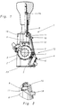
- a hand stamp apparatus designated as a whole with 1, has 2 different printing characters 3 on pressure wheels which are adjustable relative to one another. These printing characters 3 are in accordance with their upward movement following their depression. 3 can be wetted with printing ink by a self-coloring element 4 which can be pivoted against the printing wheels 2 from the position shown in FIG. 1.
- the self-inking element 4 has a felt, foam or a self-inking pad 5, which is held by a pad holder 6, which in turn can be pivoted with the help of a bearing pin 7 in a manner to be described with reference to FIG. 4.
- the rest position of the hand stamp apparatus shown in FIG. 1 1, in which the self-inking element 4 is held at a distance from the printing wheels 2, can be fixed in the manner shown in FIGS. 1 and 2 by a lock 11, which cooperates with a recess 8 on an actuating rod 9 to be pressed down and is adjustable on the stamp housing 10 .
- the back of the printing wheels 2 or the part of the stamp housing 10 containing them is protected by a cover 12.
- the cover 12 is at least partially movable against or into the interior of the stamp housing 10 from its normal position shown in FIG. 3 transversely to its extent, so that it assumes the position shown in FIG. 1 after such a movement.
- the cover 12 in the embodiment is pivotable about a lower region 13 in the use position about an approximately horizontal imaginary axis, whereby the in its upper region and gem.
- Fig. 5 u. 6 can be moved approximately horizontally back and forth at its upper edge even with respect to this locking projection 11 arranged above.
- a pivoting of the cover 12 into the interior of the housing thus leads to the locking projection 11 reaching the locking recess 8 inside the housing, because the pivoting path of the cover 12 in the region of its upper edge carrying the locking projection 11 corresponds approximately to the depth of the recess 8, possibly plus a game.
- the two different positions of the locking projection 11 can be seen primarily on the one hand in FIGS. 1 and 2 and on the other hand in FIG. 3.
- the actuating rod 9 cannot be moved further upward from its position shown in FIG. 1, which is carried out by a return spring 14. Thus, the spring 14 remains under tension. If the actuating rod 9 is pushed slightly downwards, the upwardly sloping limitation of the recess 8 can automatically push the correspondingly sloping locking projection 11 out of the recess 8, after which the spring 14 releases the actuating rod 9, which is now released, and the pressure gear train attached to it into that in FIG. 3 illustrated starting position for another stamping operation.
- the locking projection 11 is a rib stiffened plate which is integrally attached to the cover 12.
- this could be mounted on a pivot axis in the area 13.
- it can be elastically deformed and deflected in an advantageous manner and in order to save such a special pivot axis in relation to holding legs 15 that can be fixed in the housing 10 and in turn integrally connected to it.
- Fig. 5 is a cover 12 with multiple functions, which consists of a single piece and thus significantly facilitates assembly.
- two additional holding projections 16 are provided on the cover 12, which in the locked position of the locking projection 11 with counterparts 17 located on the housing 10 can be locked. 7 on both sides of the locking projection 11, locking hooks which can be deflected transversely to the locking movement as additional holding projections 16 which cooperate with counter hooks as counterparts 17 on the stamp housing 10.
- the position shown with strong lines is the open position, while the latched position is indicated by dash-dotted lines in FIGS. 7 and 8.
- the latching forces are strong enough to counteract the elastic deformation of the cover 12, but so small that the downward movement of the actuating rod 9 when the locking projection 11 is pushed back also releases this latching problem.
- a pushbutton 18 projecting from the cover 12 and from the housing 10 is arranged and formed, which facilitates operation.
- This push button 18 jumps so far that it still protrudes beyond the housing 10 even in the locked position.
- the cover 12 has on its holding legs 15 the bearing openings 19 shown in FIGS. that these bearing openings 19 are recesses which are open on one side and which are also closed towards the outside, that is to say are blind holes in the axial direction.
- the journals 7 of the self-coloring element 4 can be inserted into the bearing openings 19 transversely to their axial extent.
- stamp housing 10 and its walls 10a can thus be smooth and unperforated in the area of the pivot bearing 7 of the self-inking pad 4 and 5.
- the Groove width acc. Fig. 7 corresponds approximately to the width of the legs 15 and thus the legs 15 are positively held on both sides.
- the groove ends on the underside can be closed by a releasable base plate 23, on which base plate 23 the legs 15 are then supported with their end faces.
- Fig. 4 illustrates the storage of the self-coloring element 4 in a leg 15, wherein a rocker 24 can be seen, which converts the downward movement of the actuating rod 9 in a known manner into the pivoting movement of the self-coloring element 4.
- the one-piece cover part recognizable in FIG. 5, with its parts contributing to storage and locking, is made of plastic, which favors the one-piece production of this part.
- the cover 12 is therefore a one-piece multifunctional part made of preferably partially elastic plastic, as a result of which the manual actuation of the latching projection 11 on the one hand and the storage of the stamp pad carrier 6 on the other hand are made possible and the housing 10 for covering the printing wheels 2 is also closed.
- the hand stamp apparatus 1 for example with printing marks 3 arranged on printing wheels 2, which can be switched in different ways, in particular also when they are pressed onto the surface to be stamped, has a self-inking element 4 with inking pad 5 in order to automatically wet the printing characters 3 with printing ink, especially in the upward movement that follows after stamping. So that this self-inking element 4 does not remain in an unwanted contact position, which is achieved above all in the top position of the printing wheels 2, there is a rest position of the printing characters 3 in a position slightly lower than their top position, but above the surface to be stamped.
- the self-inking element 4 is arranged at a distance from the printing characters 2 of the printing wheels 3, and this rest position can be determined by a lock 11 which can be adjusted on the stamp housing 10 and which cooperates with a recess 8 on the actuating rod 9 of the hand stamp apparatus 1.
- This lock 11 is arranged as a locking projection on a cover 12 for the stamp housing 10 and this cover 12 can be moved or pivoted together with this locking projection 11 into the interior of the stamp housing 10, so that the locking projection 11 gets into the locking recess 8.
- a separate locking slide with corresponding guides on the stamp housing 10 can be avoided in this way.
Description
Die Erfindung betrifft einen Handstempelapparat mit auf Tragelementen, z.B. Druckrädern angeordneten Druckzeichen, die insbesondere bei ihrer auf ihr Niederdrücken folgenden Aufwärtsbewegung durch ein Selbstfärbeelement mit Druckfarbe benetzbar sind, wobei wenigstens eine Ruheposition der Druckzeichen, bei welcher das Selbstfärbeelement mit Abstand zu ihnen gehalten ist, durch eine mit einer Aussparung einer Betätigungsstange zusammenwirkende, am Stempelgehäuse verstellbare Sperre festlegbar ist und wenigstens eine Seite der Druckzeichen oder Druckräder an dem Stempelgehäuse durch eine Abdeckung geschützt sind.The invention relates to a hand stamp apparatus with on supporting elements, e.g. Print wheels arranged printing marks, which are wettable by a self-inking element with printing ink, in particular during their upward movement following their depression, at least one rest position of the printing characters, in which the self-inking element is held at a distance from them, on the stamp housing by means of a cooperation with a recess in an actuating rod adjustable lock can be fixed and at least one side of the printing characters or printing wheels on the stamp housing are protected by a cover.
Ein derartiger Handstempelapparat ist beispielsweise aus DE-GM 84 23 286 bekannt. Die zum Niederdrücken der Druckzeichen dienenden Betätigungsstange hat dabei Aussparungen, in welche die Sperre etwa rechtwinklig zur Orientierung der Betätigungsstange einschiebbar ist. Es handelt sich dabei um einen bei Gebrauchsstellung etwa horizontal verschiebbaren Schieber, der in dem in der Regel aus Spritzguß-Metall oder -Kunststoff bestehenden Stempelgehäuse des Handstempelapparates gelagert ist und in eingeschobener Position in die dann auf seiner Höhe befindliche Aussparung an der Betätigungsstange eingreifen kann. Somit ist eine weitere Bewegung der Betätigungsstange relativ zum Stempelgehäuse gesperrt und damit auch die Ruhelage festgelegt. Die Aussparung hat dabei an ihrer Oberseite eine schräge Übergangsfläche auf ihren ursprünglichen Umfang, so daß zum Lösen der Sperre ein weiteres Abwärtsdrücken der Betätigungsstange genügt, um den Sperrschieber zwangsweise wieder in Löseposition zu verstellen, der zuvor einfach von Hand in die Sperrstellung eingeschoben worden war.Such a hand stamp apparatus is known for example from DE-GM 84 23 286. The actuating rod used to depress the printed characters has recesses into which the lock can be inserted approximately at right angles to the orientation of the actuating rod. It is a slide that is approximately horizontally displaceable in the position of use, which is mounted in the stamp housing of the hand stamp apparatus, which is usually made of injection-molded metal or plastic, and can engage in the inserted position in the recess at its height on the actuating rod. So that's another Movement of the actuating rod is blocked relative to the stamp housing and thus also the rest position is determined. The recess has on its top an oblique transition surface to its original circumference, so that to release the lock, a further downward pushing of the actuating rod is sufficient to forcibly move the locking slide back into the release position, which had previously been simply pushed into the locking position by hand.
Diese an sich bedienerfreundliche Möglichkeit, eine Ruhestellung zu fixieren, verursacht vor allem einen hohen Herstellungsaufwand für das Stempelgehäuse im Bereich der Sperre und auch einen Montageaufwand, da die Sperre ein flacher Schieber ist, der eine allseits geschlossene Bohrung aufweist, durch welche die Betätigungsstange hindurchgreift. Außerdem sind die entsprechenden Führungen und Lagerungen für den Schieber an dem Stempelgehäuse vorzusehen. Gerade die Fertigung des horizontalen Führungsschlitzes in dem Spritzgießteil des Metall- oder Kunststoffgehäuses bedeutet eine schwierige Fertigung, vor allem des entsprechenden Werkzeuges.This user-friendly possibility of fixing a rest position causes, above all, a high production outlay for the stamp housing in the area of the lock and also an assembly effort, since the lock is a flat slide which has a bore which is closed on all sides and through which the actuating rod extends. In addition, the corresponding guides and bearings for the slide must be provided on the stamp housing. The production of the horizontal guide slot in the injection molded part of the metal or plastic housing means a difficult production, especially of the corresponding tool.
Weiterhin ist bei diesem bekannten Handstempelapparat ungünstig, daß die Lagerachse, um welche das Selbstfärbeelement, bevorzugt ein Selbstfärbekissen, aus seiner Ruhestellung in die Arbeitsposition und wieder zurück verschwenkt wird, in Lochungen des Stempelgehäuses befestigt sein muß. Ein weiteres separates Montageteil ist die Abdeckung, die diejenige Seite des Handstempelapparates abdeckt, der einer Schaltschwinge und ihrem Betätigungsbügel in dessen Obenstellung gegenüberliegt.Furthermore, it is unfavorable in this known hand stamp apparatus that the bearing axis, about which the self-inking element, preferably a self-inking pad, is pivoted out of its rest position into the working position and back again, must be fastened in perforations in the stamp housing. Another separate assembly part is the cover, which covers that side of the hand stamp apparatus which is opposite a switching rocker and its actuating bracket in its up position.
Der Erfindung liegt die Aufgabe zugrunde, einen Handstempelapparat der eingangs erwähnten Art zu schaffen, bei welchem die Einfachheit der Bedienung der Sperre für die Ruheposition erhalten bleibt, die Herstellung und die Montage vor allem der Sperre aber vereinfacht sind.The invention has for its object to provide a hand stamp apparatus of the type mentioned, in which the simplicity of operation of the lock for the rest position is retained, but the manufacture and assembly of the lock in particular are simplified.
Die Lösung dieser Aufgabe besteht darin, daß die Abdeckung aus ihrer Normallage quer zu ihrer Erstreckung zumindest bereichsweise in Richtung auf das Innere des Stempelgehäuses bewegbar gelagert ist und an ihrem beweglichen Teil oder Bereich einen in das Gehäuseinnere und gegen die Sperraussparung gerichteten Vorsprung als Sperre trägt. Der an der Abdeckung vorgesehene Vorsprung ersetzt somit den bisherigen Sperrschieber und es genügt, die Abdeckung in das Gehäuseinnere zu bewegen, um den Vorsprung in seine Sperrstellung zu bewegen, da die Abmessung der Bewegbarkeit der Abdeckung dem Weg entspricht, den die Sperre von der Offenstellung in ihre Schließstellung benötigt. In vorteilhafter Weise erhält also die Abdeckung eine zusätzliche Funktion, da sie die Sperre trägt und führt, so daß eine besondere Führungsaussparung für den Sperrschieber nicht mehr benötigt wird. Die Lagerung der bewegbaren Abdeckung sorgt dafür, daß der Sperrvorsprung bei der Bewegung der Abdeckung eine definierte Verstellbewegung durchführt und somit auch in die Sperrausnehmung der Betätitungsstange oder eines sonstigen zu der Stempelmechanik gehörenden Teiles gelangt.The solution to this problem is that the cover from its normal position is mounted transversely to its extent, at least in regions, in the direction of the interior of the stamp housing and carries on its movable part or region a projection directed into the housing interior and against the locking recess as a lock. The projection provided on the cover thus replaces the previous locking slide and it is sufficient to move the cover into the interior of the housing in order to move the projection into its locking position, since the dimension of the movability of the cover corresponds to the path that the lock from the open position in needs their closed position. The cover thus advantageously has an additional function, since it carries and guides the lock, so that a special guide recess for the locking slide is no longer required. The storage of the movable cover ensures that the locking projection performs a defined adjustment movement during the movement of the cover and thus also reaches the locking recess of the actuating rod or another part belonging to the stamp mechanism.
Besonders günstig ist es, wenn die Abdeckung um einen in Gebrauchsstellung unteren Bereich ihrer Halterung schwenkbar ist und der Sperrvorsprung in ihrem oberen Bereich, insbesondere am oberen Rand der Abdeckung angeordnet ist. Dadurch befindet sich der Sperrvorsprung oberhalb des Bereiches, den Druckräder oder sonstige zur Druckmechanik gehörende Teile in ihrer Ausgangsstellung einnehmen und kann außerdem an einer Stelle angeordnet werden, an der bei herkömmlichen gattungsgemäßen Stempeln der Sperrschieber in einer komplizierten Aussparung des Gehäuses gelagert ist, so daß der Sperrvorsprung an Aussparungen der Betätigungsstange oder Stempelmechanik angreifen kann, die schon vorhanden sind. Mit anderen Worten, die Gegen-Aussparung für die Sperre braucht gegenüber der bisherigen Konstruktion in keiner Weise abgeändert zu werden.It is particularly expedient if the cover can be pivoted about a lower region of its holder in the position of use and the locking projection is arranged in its upper region, in particular at the upper edge of the cover. As a result, the locking projection is above the area that the printing wheels or other parts belonging to the printing mechanism occupy in their starting position and can also be arranged at a point at which, in the case of conventional generic stamps, the locking slide is mounted in a complicated recess in the housing, so that the Locking projection on recesses in the actuating rod or punch mechanism can attack that already exist. In other words, the counter recess for the lock need not be changed in any way compared to the previous construction.
Für eine Vereinfachung der Fertigung ist es vorteilhaft, wenn der Sperrvorsprung, der insbesondere eine Leiste oder Platte ist, einstückig an der Abdeckung befestigt ist. Durch die Herstellung der Abdeckung ist dann auch der Sperrvorsprung bereits vorhanden und durch die Montage der Abdeckung an seinem richtigen Platz, wobei in vorteilhafter Weise eine besondere Schiebelagerung für die Sperre am Gehäuse entfällt, also auch der Aufwand vermieden ist, die Sperre in einer solchen speziellen Führung unterzubringen.To simplify production, it is advantageous if the locking projection, which is in particular a strip or plate, is attached in one piece to the cover. By producing the cover, the locking projection is then already present and by mounting the cover in its correct place, advantageously eliminating the need for a special sliding bearing for the lock on the housing, thus also avoiding the expense of having the lock in such a special one To accommodate leadership.
Die Abdeckung kann auf einer Schwenkachse gelagert oder gegenüber dem Gehäuse festliegenden und mit ihr verbundenen Halteschenkeln unter elastischer Verformung auslenkbar sein. Somit ist die Abdeckung schwenkbar, um ihren Sperrvorsprung in Sperrstellung zu bringen, was eine besonders einfache Lagerung ausreichen läßt, die gleichzeitig die erforderliche Führung der Verstellbewegung bewirkt.The cover can be mounted on a pivot axis or can be deflected relative to the housing and connected to it with holding legs with elastic deformation. Thus, the cover can be pivoted in order to bring its locking projection into the locking position, which allows a particularly simple storage, which at the same time brings about the required guidance of the adjustment movement.
Es kann zweckmäßig sein, wenn der Sperrvorsprung oder ein zusätzlicher Haltevorsprung in Sperrstellung des Sperrvorsprunges mit einem Gegenstück am Stempelgehäuse verrastbar ist. Dadurch kann die Sperrstellung fixiert werden, was vor allem dann vorteilhaft ist, wenn die Schwenkbewegung der Abdeckung durch eine elastische Verformung erfolgt, also - wenn auch geringe - Rückstellkräfte verursacht. Da die Sperrstellung durch die besondere Formgebung der Sperr-Ausnehmung zwangsweise wieder gelöst werden kann, kann auch eine solche Verrastung der Sperrstellung leicht wieder rückgängig gemacht werden.It can be expedient if the locking projection or an additional holding projection can be locked in the locking position of the locking projection with a counterpart on the stamp housing. As a result, the blocking position can be fixed, which is particularly advantageous if the pivoting movement of the cover is caused by an elastic deformation, that is to say — even if only slight — causes restoring forces. Since the locking position can be forcibly released again due to the special shape of the locking recess, such locking of the locking position can also be easily reversed again.
Zweckmäßig ist es dabei, wenn beidseitig des Sperrvorsprunges quer zur Sperrbewegung auslenkbare Rastkugeln, Rasthaken oder Rastöffnungen vorgesehen sind, die mit Gegenaussparungen, Gegenhaken oder Gegenrasten am Stempelgehäuse zusammenwirken.It is expedient if latching balls, latching hooks or latching openings which can be deflected transversely to the blocking movement are provided on both sides of the locking projection and interact with counter-recesses, counter-hooks or counter-latches on the stamp housing.
Um die Bedienung des Sperrvorsprunges zu erleichtern, kann an der Außenseite der Abdeckung insbesondere auf der Höhe des Sperrvorsprunges eine gegenüber der Abdeckung und vorzugsweise gegenüber dem Stempelgehäuse vorspringende Drucktaste angeordnet oder angeformt sein. Selbst bei einem relativ weiten Eindrücken der Abdeckung in das Innere des Stempelgehäuses kann auf diese Weise der Finger des Benutzers weitgehend außerhalb des Gehäuses bleiben.In order to facilitate the operation of the locking projection, a pushbutton protruding from the cover and preferably from the stamp housing can be arranged or formed on the outside of the cover, in particular at the height of the locking projection. In this way, even if the cover is pressed relatively far into the interior of the stamp housing, the user's finger can remain largely outside the housing.
Eine ganz besonders vorteilhafte und zweckmäßige Ausgestaltung der Erfindung, die eigene schutzwürdige Bedeutung hat, kann darin bestehen, daß die Abdeckung und/oder ihre Halteschenkel Lageröffnungen für Lagerzapfen des Selbstfärbeelementes oder -kissens beziehungsweise seiner Halterung aufweisen. Dadurch erhält die Abdeckung eine zusätzliche Funktion und macht Lochungen im Stempelgehäuse für eine entsprechende Lagerachse überflüssig. Dies vereinfacht die Herstellung des Stempelgehäuses und verbessert auch dessen Aussehen.A very particularly advantageous and expedient embodiment of the invention, which has its own importance worthy of protection, may consist in the cover and / or its holding legs having bearing openings for journals of the self-inking element or cushion or its holder. This gives the cover an additional function and makes perforations in the stamp housing for a corresponding bearing axis superfluous. This simplifies the manufacture of the stamp housing and also improves its appearance.
Zweckmäßig ist es dabei, wenn die Lageröffnung für an der Halterung des Selbstfärbeelementes angeordnete Lagerzapfen einseitig randoffene Aussparungen sind, die in Montagestellung von einer Rippe oder Nutenwandung an der Innenseite des Stempelgehäuses verschlossen sind. Die einseitig randoffenen Aussparungen erlauben es dabei in vorteilhafter Weise, die Abdeckung mit ihren Schenkeln von der Seite her gleichzeitig auf die beiden axial vorspringenden Lagerzapfen quer zu deren Orientierung aufzuschieben und danach die gesamte Einheit von unten her, das heißt von der Stempelfläche her, in das Gehäuse einzuschieben. Somit kann das Stempelgehäuse im Bereich der Schwenklagerung des Selbstfärbeelementes oder Selbstfärbekissens glatt und ungelocht sein.It is expedient if the bearing opening for bearing pins arranged on the holder of the self-coloring element are recesses open on one side and closed in the assembly position by a rib or groove wall on the inside of the stamp housing. The open-sided cutouts on one side advantageously allow the cover with its legs to be pushed from the side simultaneously onto the two axially projecting trunnions transversely to their orientation and then the entire unit from below, i.e. from the stamp surface, to be pushed into the housing. The stamp housing can thus be smooth and unperforated in the area of the pivot bearing of the self-inking element or self-inking cushion.
Dabei können an der Innenseite des Gehäuses nach innen vorstehende, in Gebrauchsstellung von oben nach unten verlaufende Vorsprünge eine Haltenut begrenzen, in welche die Halteschenkel der Abdeckung bei der Montage einschiebbar sind, wobei die Nutenbreite etwa der Breite der Schenkel entspricht und somit die Schenkel formschlüssig gehalten sind, und die in Gebrauchsstellung untenseitigen Nuten-Enden, durch welche die Einheit zuvor eingeschoben werden konnte, können durch eine lösbare Bodenplatte abschließbar sein, auf welcher die Schenkel mit ihren Stirnseiten in Gebrauchsstellung abgestützt sind. Dadurch sind die Halteschenkel praktisch nach allen Seiten festgelegt, denn drei Seiten werden von der Nut umschlossen, die Stirnseite wird von der Bodenplatte abgestützt und eine Verformung der beiden Schenkel zum Inneren des Gehäuses und aufeinander zu wird durch die Lagerung der Selbstfärbeeinheit und deren Achse vor allem dann verhindert, wenn die randseitig offenen Lageröffnungen zu den seitlichen Außenseiten hin nicht durchgehend sind. Darüber hinaus befindet sich im Zwischenraum zwischen den in den entsprechenden Gehäusewandungen gelagerten Schenkeln die eigentliche Druckeinheit, so daß nach dem Befestigen der Bodenplatte alle Teile gegeneinander festliegen, ohne daß die Seitenwände des Stempelgehäuses Lochungen für Lagerachsen benötigen.In this case, on the inside of the housing, protruding projections, which in the use position run from top to bottom, limit a holding groove into which the holding legs of the cover can be inserted during assembly, the groove width corresponding approximately to the width of the legs and thus the legs being held in a form-fitting manner are, and in the use position underside groove ends, through which the unit could be inserted beforehand, can be locked by a detachable base plate on which the legs are supported with their end faces in the use position. As a result, the holding legs are fixed practically on all sides, because three sides are surrounded by the groove, the front side is supported by the base plate and a deformation of the two legs towards the inside of the housing and towards each other is caused by the storage of the self-inking unit and its axis, above all then prevented if the bearing openings which are open on the edge are not continuous to the outer sides. In addition, the actual pressure unit is located in the space between the legs mounted in the corresponding housing walls, so that after attaching the base plate, all parts are fixed against one another without the side walls of the stamp housing requiring perforations for bearing axles.
Vor allem bei Kombination einzelner oder mehrerer der vorbeschriebenen Merkmale und Maßnahmen ergibt sich ein Handstempelapparat, dessen Gestell beziehungsweise Gehäuse aus Druckguß hergestellt werden kann, wobei die Gießwerkzeuge erheblich vereinfacht sind. Durch den Wegfall der Führungsöffnung für die Sperre und durch den Wegfall der Querbohrungen für die Drehachse für den Färbekissenträger werden nicht nur die Formen einfacher, sondern auch der Materialfluß während des Gießvorganges besser, weil Verwirbelungen während des Materialflusses vermindert oder vermieden werden. Gleichzeitig wird die Anzahl der Bauteile unter Beibehaltung der bisherigen Stempelfunktionen reduziert.Especially when combining one or more of the features and measures described above, a hand stamp apparatus results, the frame or housing of which can be produced from die-casting, the casting tools being considerably simplified. By eliminating the guide opening for the lock and by eliminating the cross holes for The axis of rotation for the dye pad support not only simplifies the shapes, but also the material flow during the casting process, because turbulence during the material flow is reduced or avoided. At the same time, the number of components is reduced while maintaining the previous stamp functions.
Nachstehend ist ein Ausführungsbeispiel der Erfindung anhand der Zeichnung näher beschrieben. Es zeigt in zum Teil schematisierter Darstellung:
- Fig. 1
- einen vertikalen Querschnitt durch ein erfindungsgemäßes Handstempelgerät in durch die Sperre fixierter Ruhestellung,
- Fig. 2
- in vergrößertem Maßstab einen Ausschnitt aus Fig.1 mit der Lage der Sperre in Sperrstellung bei ihrem Eingriff in die Sperr- Aussparung der vertikalen Betätigungsstange des Handstempelapparates,
- Fig. 3
- eine der Fig. 1 entsprechende Darstellung, bei welcher sich das Stempelgerät in der Einfärbestellung, also in der Bereitschaftsstellung für einen Stempelvorgang befindet und die Sperre für die Ruhestellung gelöst ist,
- Fig. 4
- eine Teilansicht des Gerätes von seiner Rückseite, teilweise geschnitten, wobei die Schnittlinie durch die Lagerung des Selbstfärbeelementes verläuft,
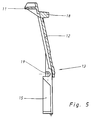
- Fig. 5
- einen Querschnitt der Abdeckung mit einstückig an ihr angebrachter Sperre und Halteschenkeln, die randseitig offene Ausnehmungen zur Lagerung der schwenkbaren Selbstfärbe-Vorrichtung haben,
- Fig. 6
- eine Ansicht der Abdeckung mit ihren Halteschenkeln und dem Sperrvorsprung,
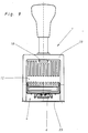
- Fig. 7
- eine Ansicht der Unterseite des Handstempelgerätes, wobei der besseren Übersicht wegen die Druckräder und ihr Räderkasten sowie die Selbstfärbeeinheit demontiert beziehungsweise weggelassen sind, so daß die Halterung der Halteschenkel der Abdeckung in seitlichen Gehäusenuten und die Ausbildung des Sperrvorsprunges sowie mit diesem zusammenwirkende Rasten erkennbar sind,
- Fig. 8
- einen Teilquerschnitt gem. der Linie VIII-VIII in Fig. 7 mit Blick auf eine die Sperrstellung fixierende Raste, in dieser Darstellung jedoch in ausgerasteter Position, sowie
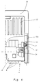
- Fig. 9
- eine Gesamtansicht der die Abdeckung aufweisenden Rückseite des Handstempelgerätes in der der Fig.3 entsprechenden Bereitschaftsstellung.
- Fig. 1
- a vertical cross section through a hand stamp device according to the invention in the rest position fixed by the lock,
- Fig. 2
- on an enlarged scale a section of Figure 1 with the position of the lock in the locking position when it engages in the locking recess of the vertical actuating rod of the hand stamp apparatus,
- Fig. 3
- 1 shows a representation corresponding to FIG. 1, in which the stamping device is in the inking order, that is to say in the ready position for a stamping operation and the lock for the rest position is released,
- Fig. 4
- a partial view of the device from its rear, partially cut, the cut line running through the storage of the self-coloring element,
- Fig. 5
- 3 shows a cross section of the cover with a lock and holding legs attached to it in one piece, which have open-sided recesses for mounting the pivotable self-coloring device,
- Fig. 6
- a view of the cover with its holding legs and the locking projection,
- Fig. 7
- a view of the underside of the hand stamp device, the pressure wheels and their wheel housing and the self-inking unit being dismantled or omitted for the sake of a better overview, so that the holding of the holding limbs of the cover in lateral housing grooves and the formation of the locking projection and detents interacting therewith can be seen,
- Fig. 8
- a partial cross section acc. the line VIII-VIII in Fig. 7 with a view of a locking position locking, but in this illustration in the disengaged position, and
- Fig. 9
- an overall view of the cover having the back of the hand stamp device in the standby position corresponding to FIG. 3.
Ein im ganzen mit 1 bezeichneter Handstempelapparat hat an gegeneinander verstellbaren Druckrädern 2 unterschiedliche Druckzeichen 3. Diese Druckzeichen 3 sind bei ihrer auf ihr Niederdrücken folgenden Aufwärtsbewegung gem. Fig. 3 durch ein aus der in Fig. 1 erkennbaren Lage gegen die Druckräder 2 verschwenkbares Selbstfärbeelement 4 mit Druckfarbe benetzbar. Das Selbstfärbeelement 4 weist dabei einen Filz, Schaum beziehungsweise ein Selbstfärbekissen 5 auf, welches von einem Kissenträger 6 gehalten wird, der seinerseits mit Hilfe eines Lagerzapfens 7 in anhand der Fig. 4 noch zu beschreibender Weise verschwenkt werden kann.A hand stamp apparatus, designated as a whole with 1, has 2
Die in Fig. 1 dargestellte Ruheposition des Handstempelapparates 1, in welcher das Selbstfärbeelement 4 mit Abstand zu den Druckrädern 2 gehalten wird, ist durch eine mit einer Aussparung 8 an einer abwärts zu drückenden Betätigungsstange 9 zusammenwirkenden, am Stempelgehäuse 10 verstellbare Sperre 11 in der in Fig. 1 u.2 dargestellten Weise festlegbar. Die Rückseite der Druckräder 2 beziehungsweise des sie enthaltenden Teiles des Stempelgehäuses 10 ist durch eine Abdeckung 12 geschützt.The rest position of the hand stamp apparatus shown in FIG. 1 1, in which the self-inking
Die Abdeckung 12 ist aus ihrer in Fig. 3 erkennbaren Normallage quer zu ihrer Erstreckung zumindest bereichsweise gegen oder in das Innere des Stempelgehäuses 10 bewegbar gelagert, so daß sie nach einer solchen Bewegung die in Fig. 1 dargestellte Lage einnimmt. An ihrem beweglichen Teil oder Bereich trägt sie einen in das Gehäuseinnere und gegen die Sperraussparung 8 gerichteten Vorsprung als Sperre 11, der im folgenden auch "Sperrvorsprung 11" genannt ist.The
Aus dem Vergleich der Figuren 1 u.3 wird deutlich, daß die Abdeckung 12 im Ausführungsbeispiel um einen in Gebrauchsstellung unteren Bereich 13 um eine etwa horizontal verlaufende gedachte Achse schwenkbar ist, wodurch der in ihrem oberen Bereich und gem. Fig. 5 u. 6 an ihrem oberen Rand sogar gegenüber diesem vorstehend angeordnete Sperrvorsprung 11 etwa horizontal hin und herbewegt werden kann. Eine Verschwenkung der Abdeckung 12 in das Gehäuseinnere führt somit dazu, daß der Sperrvorsprung 11 im Inneren des Gehäuses in die Sperraussparung 8 gelangt, denn der Schwenkweg der Abdeckung 12 im Bereich ihres oberen, den Sperrvorsprung 11 tragenden Randes entspricht etwa der Tiefe der Aussparung 8, eventuell zuzüglich eines Spieles. Die beiden unterschiedlichen Lagen des Sperrvorsprunges 11 erkennt man vor allem einerseits in Fig.1 u.2 und andererseits in Fig.3.From the comparison of Figures 1 and 3 it is clear that the
Da die Aussparung an ihrer Unterseite einen etwa horizontalen Absatz hat, kann bei in sie eingreifendem Sperrvorsprung 11 die Betätigungsstange 9 nicht aus ihrer in Fig. 1 erkennbaren Position weiter nach oben verschoben werden, was durch eine Rückholfeder 14 durchgeführt wird. Somit bleibt die Feder 14 gespannt. Wird die Betätigungsstange 9 geringfügig abwärtsgedrückt, kann die nach oben schräge Begrenzung der Aussparung 8 den entsprechend schräg gestalteten Sperrvorsprung 11 selbsttätig aus der Aussparung 8 ausschieben, wonach die Feder 14 die nun frei gegebene Betätigungsstange 9 und das daran hängende Druckräderwerk in die in Fig. 3 dargestellte Ausgangslage für einen weiteren Stempelvorgang anheben kann.Since the recess has an approximately horizontal shoulder on its underside, when the locking
Gemäß Fig. 2, 5 und 6 ist der Sperrvorsprung 11 eine durch Rippen versteifte Platte, die einstückig an der Abdeckung 12 befestigt ist.2, 5 and 6, the locking
Zur Durchführung der Sperrbewegung mit Hilfe der Abdeckung 12 könnte diese auf einer Schwenkachse im Bereich 13 gelagert sein. Sie ist jedoch im Ausführungsbeispiel in vorteilhafter Weise und zur Einsparung einer solchen speziellen Schwenkachse gegenüber im Gehäuse 10 festlegbaren und mit ihr wiederum einstückig verbundenen Halteschenkeln 15 elastisch verformbar und auslenkbar. Somit ergibt sich gem. Fig. 5 eine Abdeckung 12 mit mehreren Funktionen, die insgesamt aus einem einzigen Stück besteht und somit die Montage erheblich erleichtert.To carry out the locking movement with the aid of the
Damit die elastischen Reaktionskräfte der in Sperrstellung befindlichen Abdeckung 12 nicht zu einer ungewollten Lösebewegung führen können, sind im Ausführungsbeispiel gem. den Fig. 7 u.8 zwei zusätzliche Haltevorsprünge 16 an der Abdeckung 12 vorgesehen, die in Sperrstellung des Sperrvorsprunges 11 mit am Gehäuse 10 befindlichen Gegenstücken 17 verrastbar sind. Dabei erkennt man in Fig. 7 beidseitig des Sperrvorsprunges 11 quer zur Sperrbewegung auslenkbare Rasthaken als zusätzliche Haltevorsprünge 16, die mit Gegenhaken als Gegenstücke 17 am Stempelgehäuse 10 zusammenwirken. Die mit starken Strichen dargestellte Position ist die Offenstellung, während die verrastete Position strichpunktiert in Fig. 7 u.8 angedeutet ist. Die Rastkräfte sind dabei stark genug, um der elastischen Verformung der Abdeckung 12 entgegenzuwirken, jedoch so gering, daß die Abwärtsbewegung der Betätigungsstange 9 beim Zurückschieben des Sperrvorsprunges 11 auch diese Verrastung problemlos löst.So that the elastic reaction forces of the
An der Außenseite der Abdeckung 12 nahezu auf der Höhe des Sperrvorsprunges 11 ist eine gegenüber der Abdeckung 12 und gegenüber dem Gehäuse 10 vorspringende Drucktaste 18 angeordnet und angeformt, die die Bedienung erleichtert. Diese Drucktaste 18 springt dabei so weit vor, daß sie sogar in Sperrstellung noch über das Gehäuse 10 vorsteht.On the outside of the
Zur Vermeidung einer Lagerachse, die die Seitenwandungen 10a des Stempelgehäuses 10 durchsetzen müßte, hat die Abdeckung 12 an ihren Halteschenkeln 15 die in den Figuren 4 u.5 erkennbaren Lageröffnungen 19 für die Lagerzapfen 7 des Selbstfärbeelementes 4 bezeihungsweise seiner Halterung 5. Dabei erkennt man, daß diese Lageröffnungen 19 einseitig randoffene Aussparungen sind, die auch nach der Außenseite hin abgeschlossen sind, also in Axialrichtung Sacklochungen sind. Somit können die Lagerzapfen 7 des Selbstfärbeelementes 4 quer zu ihrer axialen Erstreckung in die Lageröffnungen 19 eingeführt werden.To avoid a bearing axis, which would have to penetrate the
Vor allem Fig. 7 verdeutlicht, daß die Halteschenkel 15 in Montagestellung von Rippen oder Nutenwandungen an der Innenseite des Stempelgehäuses 10 und der Stempelwandung 10a umschlossen sind, so daß dadurch auch die randoffene Lageröffnung 19 abgeschlossen wird. Das Stempelgehäuse 10 und seine Wandungen 10a können also im Bereich der Schwenklagerung 7 des Selbstfärbekissens 4 und 5 glatt und ungelocht sein.7 illustrates in particular that the holding
Wie erwähnt, begrenzen an der Innenseite des Gehäuses 10 nach innen vorstehende, in Gebrauchsstellung von oben nach unten verlaufende Vorsprünge 21 und 22 die Haltenut, in welche die Halteschenkel 15 der Abdeckung 12 bei der Montage von der Stempelapparat-Unterseite her einschiebbar sind, wobei die Nutenbreite gem. Fig. 7 etwa der Breite der Schenkel 15 entspricht und somit die Schenkel 15 beidseitig formschlüssig gehalten sind. In Gebrauchsstellung können die untenseitigen Nuten-Enden durch eine lösbare Bodenplatte 23 verschlossen werden, auf welcher Bodenplatte 23 die Schenkel 15 dann mit ihren Stirnseiten abgestützt sind.As mentioned, on the inside of the
Somit trägt die Abdeckung 12 auch dazu bei, wichtige Teile des Handstempelapparates zu lagern und am Stmepelgehäuse 10 festzulegen, ohne daß dieses störende Durchbrüche haben muß. Fig. 4 verdeutlicht die Lagerung des Selbstfärbeelementes 4 in einem Schenkel 15, wobei eine Schwinge 24 erkennbar ist, die die Abwärtsbewegung der Betätigungsstange 9 in bekannter Weise in die Schwenkbewegung des Selbstfärbeelementes 4 umsetzt.Thus, the
Zweckmäßig ist es, wenn das in Fig. 5 erkennbare, einstükkige Abdeckteil mit seinen zur Lagerung und zur Sperrung beitragenden Teilen aus Kunststoff besteht, wodurch die einstückige Fertigung dieses Teiles begünstigt wird.It is expedient if the one-piece cover part recognizable in FIG. 5, with its parts contributing to storage and locking, is made of plastic, which favors the one-piece production of this part.
Die Abdeckung 12 ist also im Ausführungsbeispiel ein einstückiges Mehrfunktionsteil aus vorzugsweise teilelastischem Kunststoff, wodurch die manuelle Betätigung des Rastvorsprunges 11 einerseits und die Lagerung des Stempelkissenträgers 6 andererseits ermöglicht werden und dabei auch das Gehäuse 10 zur Abdeckung der Druckräder 2 abgeschlossen wird.In the exemplary embodiment, the
Der Handstempelapparat 1 mit zum Beispiel auf Druckrädern 2 angeordneten Druckzeichen 3, die auf unterschiedliche Weise, insbesondere auch bei ihrem Niederdrücken auf die zu bestempelnde Fläche weiterschaltbar sein können, hat ein Selbstfärbeelement 4 mit Färbekissen 5, um die Druckzeichen 3 mit Druckfarbe automatisch zu benetzen, insbesondere bei der nach dem Stempeln folgenden Aufwärtsbewegung. Damit dieses Selbstfärbeelement 4 nicht in einer ungewollten Berührposition verbleibt, die vor allem in der Obenstellung der Druckräder 2 erreicht ist, gibt es eine Ruheposition der Druckzeichen 3 in einer gegenüber ihrer Obenstellung etwas tieferliegenden Position, aber oberhalb der zu bestempelnden Fläche. In dieser Position ist das Selbstfärbeelement 4 mit Abstand zu den Druckzeichen 2 der Druckräder 3 angeordnet und diese Ruheposition kann durch eine mit einer Aussparung 8 an der Betätigungsstange 9 des Handstempelapparates 1 zusammenwirkende, am Stempelgehäuse 10 verstellbare Sperre 11 festgelegt werden. Diese Sperre 11 ist als Sperrvorsprung an einer Abdeckung 12 für das Stempelgehäuse 10 angeordnet und diese Abdeckung 12 kann zusammen mit diesem Sperrvorsprung 11 in das Innere des Stempelgehäuses 10 bewegt oder verschwenkt werden, damit der Sperrvorsprung 11 in die Sperraussparung 8 gelangt. Ein eigener Sperrschieber mit entsprechenden Führungen am Stempelgehäuse 10 kann auf diese Weise vermieden werden.The
Claims (12)
- A hand stamp (1) having print characters (3) that are arranged on carrying elements, e.g. printing wheels (2), and are inkable by a self-inking element (4) particularly during their upward movement following their depression, wherein at least one rest position of the print characters, in which the self-inking element (4) is held in spaced relationship to them, is fixable by means of a lock (11) that is relocatable at the stamp housing (10) and co-operates with a recess (8) of an actuating rod (9), and at least one side of the print characters or printing wheels are protected at the stamp housing (10) by a cover (12), characterized in that the cover (12) is mounted so as to be movable transversely of its expanse to depart from its normal position and move at least in part towards the interior of the stamp housing (10), said cover carrying on the movable part or zone thereof a projection in the form of a lock directed into the interior of the housing and towards the recess (8).
- A hand stamp as claimed in claim 1, characterized in that the cover (12) is adapted to swivel about a lower zone (13) in the position of use and the locking projection (11) is arranged in the upper zone, particularly at the upper edge of the cover (12).
- A hand stamp as claimed in claim 1 or claim 2, characterized in that the locking projection (11), particularly a strip or plate, is integrally attached to the cover (12).
- A hand stamp as claimed in any one of claims 1 to 3, characterized in that the cover (12) is mounted on a swivel pin or is deflectable under elastic deformation relative to holding arms (15) fixed in the housing (10) and connected to said cover.
- A hand stamp as claimed in any one of claims 1 to 4, characterized in that in the locking position of the locking projection (11), the locking projection or an additional retaining projection (16) is interlockable with a companion part (17).
- A hand stamp as claimed in any one of claims 1 to 5, characterized in that arresting balls, arresting hooks or the like deflectable transversely of the locking movement are provided on either side of the locking projection (11) and co-operate with mating recesses, mating hooks or the like on the stamp housing (10).
- A hand stamp as claimed in any one of claims 1 to 6, characterized in that a push-button (8) projecting relative to the cover (12) and preferably relative to the stamp housing (10) is arranged on or integral with the outside of the cover (12), particularly at the level of the locking projection (11).
- A hand stamp particularly as claimed in any one of the preceding claims, characterized in that the cover (12) and/or holding arms (15) thereof have bearing openings (19) for journals (7) of the self-inking element/pad or holder of the self-inking element/pad.
- A hand stamp as claimed in any one of claims 1 to 8, characterized in that the bearing openings (19) for journals arranged on the holder of the self-inking element (4) are recesses open at one end that are closed in the assembled position by a rib (22) or a slot wall at the inside of the stamp housing.
- A hand stamp as claimed in any one of claims 1 to 9, characterized in that the stamp housing is smooth and unperforated in the area of the swivel bearing of the self-inking pad.
- A hand stamp as claimed in any one of claims 1 to 10, characterized in that, at the inside of the housing, inward projections running from top to bottom in the position of use define a keeper slot into which, during assembly, the holding arms (15) of the cover (12) are insertable, the width of the slot approximating the width of the arms (15) and therefore holding the arms (15) with a positive fit, and that the ends of the slot that are situated at the bottom in the position of use are closable by a detachable base plate supporting the end faces of the arms.
- A hand stamp as claimed in any one of claims 1 to 11, characterized in that the cover consists of plastic.
Applications Claiming Priority (2)
| Application Number | Priority Date | Filing Date | Title |
|---|---|---|---|
| DE4114451 | 1991-05-03 | ||
| DE4114451A DE4114451C1 (en) | 1991-05-03 | 1991-05-03 |
Publications (2)
| Publication Number | Publication Date |
|---|---|
| EP0512224A1 EP0512224A1 (en) | 1992-11-11 |
| EP0512224B1 true EP0512224B1 (en) | 1995-02-01 |
Family
ID=6430895
Family Applications (1)
| Application Number | Title | Priority Date | Filing Date |
|---|---|---|---|
| EP92104639A Expired - Lifetime EP0512224B1 (en) | 1991-05-03 | 1992-03-18 | Hand stamp with self-inking unit |
Country Status (3)
| Country | Link |
|---|---|
| EP (1) | EP0512224B1 (en) |
| DE (2) | DE4114451C1 (en) |
| ES (1) | ES2067972T3 (en) |
Families Citing this family (1)
| Publication number | Priority date | Publication date | Assignee | Title |
|---|---|---|---|---|
| AT522201B1 (en) * | 2019-02-26 | 2021-08-15 | Trodat Gmbh | Stamp with a cap and a cap for a stamp |
Family Cites Families (2)
| Publication number | Priority date | Publication date | Assignee | Title |
|---|---|---|---|---|
| US1555527A (en) * | 1925-03-03 | 1925-09-29 | Wm A Force & Company Inc | Numbering machine |
| DE8423286U1 (en) * | 1984-08-04 | 1984-10-31 | Ernst Reiner GmbH & Co KG, 7743 Furtwangen | HAND STAMP WITH PRINTED WHEELS |
-
1991
- 1991-05-03 DE DE4114451A patent/DE4114451C1/de not_active Expired - Fee Related
-
1992
- 1992-03-18 ES ES92104639T patent/ES2067972T3/en not_active Expired - Lifetime
- 1992-03-18 EP EP92104639A patent/EP0512224B1/en not_active Expired - Lifetime
- 1992-03-18 DE DE59201317T patent/DE59201317D1/en not_active Expired - Fee Related
Also Published As
| Publication number | Publication date |
|---|---|
| ES2067972T3 (en) | 1995-04-01 |
| DE4114451C1 (en) | 1992-10-08 |
| EP0512224A1 (en) | 1992-11-11 |
| DE59201317D1 (en) | 1995-03-16 |
Similar Documents
| Publication | Publication Date | Title |
|---|---|---|
| EP1280669B1 (en) | Self-inking stamp | |
| EP1841599B1 (en) | Device for securing the pivot pin of a type unit | |
| AT501174B1 (en) | HAND TEMPLE-TYPE UNIT | |
| EP1603755B1 (en) | Self-inking stamp with inking from the top and ink cushion container therefor | |
| EP1673229B1 (en) | Self-inking hand stamp | |
| EP1796909B1 (en) | Manual stamp with coupled lid | |
| EP2714410B1 (en) | Stamp and process for mounting a stamp plate | |
| EP1603754A1 (en) | Self-inking stamp filled by pressure over inking and an ink-pad container for said stamp | |
| EP2591920A1 (en) | Stamp | |
| EP0782930B1 (en) | Hand stamp | |
| DE3334510A1 (en) | FASTENING MECHANISM FOR A SEAT BELT FOR MOTOR VEHICLES | |
| EP1255650B1 (en) | Self-inking stamp | |
| DE2856978C1 (en) | Container with fold-out legs | |
| EP3914455B1 (en) | Hand-operated stamp having a tilting element | |
| EP0512224B1 (en) | Hand stamp with self-inking unit | |
| DE2826991C2 (en) | Hand-held labeling device for printing, dispensing and attaching self-adhesive labels | |
| WO2004091923A1 (en) | Stamp and reversing mechanism for a stamp | |
| DE3103449C2 (en) | ||
| DE2102385C3 (en) | Key switch panel mechanism | |
| DE2430496B2 (en) | Writing implement with a pocket clip designed as a clamp | |
| EP3752368B1 (en) | Stamp, in particular a date stamp | |
| DE2044066A1 (en) | Toggle lever lock for lights with cover | |
| AT522201A1 (en) | Stamp with a sealing cap and a sealing cap for a stamp | |
| DE1808437C (en) | Push button voting device | |
| DE2705031A1 (en) | TILT VALVE, E.g. FOR AEROSOL CONTAINER |
Legal Events
| Date | Code | Title | Description |
|---|---|---|---|
| PUAI | Public reference made under article 153(3) epc to a published international application that has entered the european phase |
Free format text: ORIGINAL CODE: 0009012 |
|
| AK | Designated contracting states |
Kind code of ref document: A1 Designated state(s): DE ES FR GB IT |
|
| 17P | Request for examination filed |
Effective date: 19921028 |
|
| 17Q | First examination report despatched |
Effective date: 19940415 |
|
| GRAA | (expected) grant |
Free format text: ORIGINAL CODE: 0009210 |
|
| AK | Designated contracting states |
Kind code of ref document: B1 Designated state(s): DE ES FR GB IT |
|
| GBT | Gb: translation of ep patent filed (gb section 77(6)(a)/1977) |
Effective date: 19950209 |
|
| REF | Corresponds to: |
Ref document number: 59201317 Country of ref document: DE Date of ref document: 19950316 |
|
| REG | Reference to a national code |
Ref country code: ES Ref legal event code: FG2A Ref document number: 2067972 Country of ref document: ES Kind code of ref document: T3 |
|
| ITF | It: translation for a ep patent filed |
Owner name: ING. ZINI MARANESI & C. S.R.L. |
|
| ET | Fr: translation filed | ||
| PLBE | No opposition filed within time limit |
Free format text: ORIGINAL CODE: 0009261 |
|
| STAA | Information on the status of an ep patent application or granted ep patent |
Free format text: STATUS: NO OPPOSITION FILED WITHIN TIME LIMIT |
|
| 26N | No opposition filed | ||
| PGFP | Annual fee paid to national office [announced via postgrant information from national office to epo] |
Ref country code: FR Payment date: 20000131 Year of fee payment: 9 |
|
| PGFP | Annual fee paid to national office [announced via postgrant information from national office to epo] |
Ref country code: ES Payment date: 20000308 Year of fee payment: 9 |
|
| PG25 | Lapsed in a contracting state [announced via postgrant information from national office to epo] |
Ref country code: ES Free format text: LAPSE BECAUSE OF NON-PAYMENT OF DUE FEES Effective date: 20010319 |
|
| PG25 | Lapsed in a contracting state [announced via postgrant information from national office to epo] |
Ref country code: FR Free format text: LAPSE BECAUSE OF NON-PAYMENT OF DUE FEES Effective date: 20011130 |
|
| REG | Reference to a national code |
Ref country code: FR Ref legal event code: ST |
|
| REG | Reference to a national code |
Ref country code: GB Ref legal event code: IF02 |
|
| REG | Reference to a national code |
Ref country code: ES Ref legal event code: FD2A Effective date: 20020411 |
|
| PG25 | Lapsed in a contracting state [announced via postgrant information from national office to epo] |
Ref country code: IT Free format text: LAPSE BECAUSE OF NON-PAYMENT OF DUE FEES;WARNING: LAPSES OF ITALIAN PATENTS WITH EFFECTIVE DATE BEFORE 2007 MAY HAVE OCCURRED AT ANY TIME BEFORE 2007. THE CORRECT EFFECTIVE DATE MAY BE DIFFERENT FROM THE ONE RECORDED. Effective date: 20050318 |
|
| PGFP | Annual fee paid to national office [announced via postgrant information from national office to epo] |
Ref country code: DE Payment date: 20070226 Year of fee payment: 16 |
|
| PGFP | Annual fee paid to national office [announced via postgrant information from national office to epo] |
Ref country code: GB Payment date: 20070308 Year of fee payment: 16 |
|
| GBPC | Gb: european patent ceased through non-payment of renewal fee |
Effective date: 20080318 |
|
| PG25 | Lapsed in a contracting state [announced via postgrant information from national office to epo] |
Ref country code: DE Free format text: LAPSE BECAUSE OF NON-PAYMENT OF DUE FEES Effective date: 20081001 |
|
| PG25 | Lapsed in a contracting state [announced via postgrant information from national office to epo] |
Ref country code: GB Free format text: LAPSE BECAUSE OF NON-PAYMENT OF DUE FEES Effective date: 20080318 |