EP0512207A1 - Hermaphrodischer Steckverbinder - Google Patents
Hermaphrodischer Steckverbinder Download PDFInfo
- Publication number
- EP0512207A1 EP0512207A1 EP92103318A EP92103318A EP0512207A1 EP 0512207 A1 EP0512207 A1 EP 0512207A1 EP 92103318 A EP92103318 A EP 92103318A EP 92103318 A EP92103318 A EP 92103318A EP 0512207 A1 EP0512207 A1 EP 0512207A1
- Authority
- EP
- European Patent Office
- Prior art keywords
- arm
- elongated
- arms
- terminals
- edges
- Prior art date
- Legal status (The legal status is an assumption and is not a legal conclusion. Google has not performed a legal analysis and makes no representation as to the accuracy of the status listed.)
- Withdrawn
Links
Images

Classifications
-
- H—ELECTRICITY
- H01—ELECTRIC ELEMENTS
- H01R—ELECTRICALLY-CONDUCTIVE CONNECTIONS; STRUCTURAL ASSOCIATIONS OF A PLURALITY OF MUTUALLY-INSULATED ELECTRICAL CONNECTING ELEMENTS; COUPLING DEVICES; CURRENT COLLECTORS
- H01R13/00—Details of coupling devices of the kinds covered by groups H01R12/70 or H01R24/00 - H01R33/00
- H01R13/02—Contact members
- H01R13/28—Contacts for sliding cooperation with identically-shaped contact, e.g. for hermaphroditic coupling devices
Definitions
- This invention generally relates to the art of electrical connectors and, particularly, to a hermaphroditic terminal for use in electrical connectors.
- electrical connectors In some environments, electrical connectors must be disconnected and reconnected frequently by field personnel in relatively uncontrolled situations. One example is in the field of computers and similar equipment. Such electrical connectors should be designed to minimize the possibility of damage from any misalignment of the terminals that may occur. Usually, where repeated disconnections and reconnections are anticipated, the terminals of such connectors are designed to have relatively low insertion forces, again to prevent damage to the terminals due to the frequent disconnect and reconnect usage.
- terminals for use with electrical connectors of the character described above is the configuration of terminal studs or pins which are inserted into hollow terminal cylinders or sockets.
- One of the problems with pin and socket terminal configurations is that there really is no defined points of contact and the terminals begin to loosen in such repeated disconnect/reconnect environments.
- tooling costs and inventory management involve a factor of two because of the different structures of the mating terminals.
- hermaphroditic terminals have been designed such that two identical terminals and/or their housings are mateable with one another.
- Hermaphroditically constructed terminals and housings substantially reduce tooling costs and factory inventory.
- many hermaphroditic terminals can be designed with positive points of contact versus the telescoping contact configuration of a pin in a hollow socket.
- This invention is directed to providing a hermaphroditic terminal which is extremely simple to manufacture and which provides up to four or six elongated points of positive contact between the terminals.
- An object, therefore, of the invention is to provide a new and improved hermaphroditic terminal for use in a mating electrical terminal structure.
- the hermaphroditic terminal is bifurcated to define a pair of elongated arms.
- Each arm has a pair of elongated spaced edges facing the other arm.
- One of the arms is larger in cross-sectional dimensions than the other arm to locate the elongated edges of the one arm outside the elongated edges of the other arm. Therefore, when the terminals are mated, a four-point elongated contact array is provided between the pairs of elongated edges of the larger dimensioned arms of the respective mated terminals and between the pairs of elongated edges of the smaller dimensioned arms of the respective mated terminals.
- each terminal construction described immediately above is extremely simple to manufacture as a unitary stamped and formed metal component having either a generally rectangular or semicircular cross section.
- the mating portion of each terminal is generally cylindrical whereby each arm of each terminal is generally semi-cylindrical, the one arm of each terminal being of a larger radius than the other arm to locate the elongated edges along the semi-cylindrical configurations in a four-point contact array as described above.
- the electrical terminal structure includes a pair of hermaphroditic terminals which are trifurcated to define three elongated arms for each terminal.
- the arms include a central arm and two outside arms.
- the central arm has a pair of elongated spaced edges facing in one direction.
- the outside arms have elongate contact portions in transverse registry with and spaced from the elongated edges of the central arm.
- Each outside arm has an elongated edge facing in a direction opposite the direction of the elongated spaced edges of the central arm.
- a six-point elongated contact array is provided between the pairs of elongated edges of the central arms and the elongated contact portions of the outside arms of the respective mated terminals and between the elongated edges of the outside arms of the respective mated terminals.
- each hermaphroditic terminal is very simply fabricated of stamped and formed metal material, with the central arm of each hermaphroditic terminal being generally semi-cylindrical.
- Each outside arm is generally planar to define the contact portion thereof, with the elongated edge thereof being defined by an inwardly turned edge of the planar contact portion.
- each terminal includes a rear crimping portion including two pairs of crimp arms 12 and 14.
- crimp arms 12 are provided for clamping onto an insulating jacket of an insulated wire to provide strain relief thereon.
- Crimp arms 14 are provided for clamping onto an exposed length of a conductive core of the insulated wire, stripped of the insulating jacket, to terminate the conductor to the terminal.
- terminal 10 be provided with a bifurcated mating portion, generally designated 16, at its forward end.
- the bifurcated mating portion is generally cylindrical and includes a pair of elongated arms 18 and 20 which are generally semi-cylindrical.
- Each arm 18 and 20 is provided with an elongated slot 22 to provide resiliency therefor.
- the terminal is easily stamped and formed as a unitary component from sheet metal material. Therefore, each semi-cylindrical arm 18 and 20 of cylindrical bifurcated mating portion 16 is provided with a pair of elongated spaced edges 24 and 26, respectively, facing the other arm.
- the invention contemplates that one of semi-cylindrical arms 18,20 be of a larger crosssectional dimension or diameter than the other arm.
- this differential dimensioning locates the elongated edges of the larger diameter arm outside the elongated edges of the other arm.
- arm 20 is of a larger diameter than arm 18.
- a web 30 interconnects arm 18 with arm 20 and offsets the smaller diameter arm 18 inside of and concentric with larger diameter arm 20.
- a positive four-point elongated contact array is provided between the mating terminals.
- This array is illustrated in Figure 4 wherein it can be seen that the outside or larger diameter arm 20 of each mated terminal is disposed outside the inner or smaller diameter arm 18 of the other terminal.
- Opposing edges 24 of the two inner or smaller diameter arms of the two mated terminals define two positive points of contact, and the opposing edges 26 of the two outside or larger diameter arms of the two terminals define two additional positive points of contact.
- the hermaphroditic terminals be stamped and formed so that there are resilient forces between the arms biasing the respective opposing edges against each other to provide the positive four-point contact array.
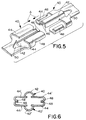
- FIG. 5 shows another form of the invention wherein a hermaphroditic terminal, generally designated 40, provides a six-point elongated contact array with an identical mated terminal. Two identical terminals are shown in Figure 5, reversed 180° in orientation for mating in the direction of arrows A.
- Each terminal 40 will have some form of means for termination to an electrical wire, such as crimp arms 12 and 14 (Fig. 1) for terminating the core of an insulated wire and providing strain relief thereon.
- each terminal 40 is stamped and formed generally to have a trifurcated configuration defining three elongated arms, including a central arm 42 and two outside arms 44.
- Central arm 42 is generally semi-cylindrical to define a pair of elongated spaced edges 46 with a taper at the forward leading portion of both edges.
- Outside arms 44 are generally planar and include inwardly turned flanges which define two edges or points of contact 48.
- the edges of arms 44 which face each other have a chamfer formed at its leading edge which assists in the mating of arms 44 with central arm 42.
- hermaphroditic terminal 40 is easily stamped and formed from sheet metal material. Aperture 50 is provided to relieve stress in the metal during the forming process of the terminal.
- the terminal is formed such that edges 46 of the right-hand terminal 40 will engage the top of planar arms 44 of the left-hand terminal, as viewed in Figure 5. Therefore, two elongated points of contact are formed between each semi-cylindrical arm 42 of each terminal with the planar arms 44 of the other terminal, resulting in four additional elongated points of contact between the mated terminals.
- FIG. 6 These six elongated points of contact are illustrated in Figure 6.
- reference numerals having the "prime” notation are applied to the arms and edges of one of the identical terminals in order to facilitate the illustration.
- central arm 42 of one terminal is shown to have its elongated edges 46 in contact with the top of planar arms 44' of the mating terminal.
- central arm 42' is shown to have its elongated edges 46' in contact with the bottoms of planar arms 44 of the opposite terminal. Therefore, four elongated points of contact are provided between the two edges of the two central arms and the two planar arms of the opposing terminals.
- inwardly turned flanges 48 of terminal 40 and inwardly turned flanges 48' of terminal 40' are in biased engagement to provide two additional elongated points of contact, totalling a six-point contact array when two hermaphroditic terminals are mated.
- the central arm and the outside arms of the terminal are located so that there is provided biasing forces between the various arms at the six points of contact to provide positive engagement between the various components, such as a press-fit with many electrical connector terminals.
Landscapes
- Manufacturing Of Electrical Connectors (AREA)
Applications Claiming Priority (2)
| Application Number | Priority Date | Filing Date | Title |
|---|---|---|---|
| US07/667,789 US5108304A (en) | 1991-03-11 | 1991-03-11 | Hermaphroditic terminal |
| US667789 | 1996-06-21 |
Publications (1)
| Publication Number | Publication Date |
|---|---|
| EP0512207A1 true EP0512207A1 (de) | 1992-11-11 |
Family
ID=24679649
Family Applications (1)
| Application Number | Title | Priority Date | Filing Date |
|---|---|---|---|
| EP92103318A Withdrawn EP0512207A1 (de) | 1991-03-11 | 1992-02-27 | Hermaphrodischer Steckverbinder |
Country Status (2)
| Country | Link |
|---|---|
| US (1) | US5108304A (de) |
| EP (1) | EP0512207A1 (de) |
Cited By (2)
| Publication number | Priority date | Publication date | Assignee | Title |
|---|---|---|---|---|
| EP0984517A2 (de) * | 1998-08-31 | 2000-03-08 | The Whitaker Corporation | Elektrischer Büchsenkontakt |
| CN108292814A (zh) * | 2015-01-16 | 2018-07-17 | 安费诺有限公司 | 具有边缘长度不同的尖齿的电触点 |
Families Citing this family (16)
| Publication number | Priority date | Publication date | Assignee | Title |
|---|---|---|---|---|
| JPH08213082A (ja) * | 1994-10-21 | 1996-08-20 | Whitaker Corp:The | 電気端子及びそれを使用する電気コネクタ |
| US5857867A (en) * | 1997-07-17 | 1999-01-12 | The Whitaker Corporation | Hermaphroditic coaxial connector |
| IT1296198B1 (it) * | 1997-11-21 | 1999-06-11 | Framatome Connectors Italia | Terminale elettrico. |
| US6899572B1 (en) * | 1999-08-16 | 2005-05-31 | Anderson Power Products | Electrical socket contact with tines |
| US6287156B1 (en) | 2000-08-31 | 2001-09-11 | Lear Corporation | Electrical terminal connector |
| WO2004100321A1 (en) * | 2003-05-02 | 2004-11-18 | Anderson Power Products | A biased socket contact and a method thereof |
| US7033194B1 (en) | 2004-12-14 | 2006-04-25 | Yazaki North America, Inc. | Standardized electrical terminal |
| US7140928B1 (en) | 2006-01-12 | 2006-11-28 | Etco, Inc. | Contact for an electrical connector |
| US20070275582A1 (en) * | 2006-05-16 | 2007-11-29 | Christopher Sommovigo | Electrical Connector |
| WO2008034957A1 (fr) | 2006-09-22 | 2008-03-27 | Fci | Contact electrique hermaphrodite |
| DE102008036128B3 (de) * | 2008-08-01 | 2009-10-15 | Hans Simon | Steckverbinder |
| US8079863B2 (en) * | 2009-09-11 | 2011-12-20 | Hubbell Incorporated | Electrical terminal with hermaphiditic connection section |
| US9362646B2 (en) | 2013-03-15 | 2016-06-07 | Amphenol Corporation | Mating interfaces for high speed high density electrical connector |
| JP6268606B2 (ja) * | 2014-11-10 | 2018-01-31 | 株式会社オートネットワーク技術研究所 | 端子金具 |
| JP7068056B2 (ja) * | 2018-06-11 | 2022-05-16 | 矢崎総業株式会社 | 接続端子及び端子接続構造 |
| US11296449B2 (en) | 2020-04-30 | 2022-04-05 | Lear Corporation | Electrical connector assembly having identical electrical connectors |
Citations (4)
| Publication number | Priority date | Publication date | Assignee | Title |
|---|---|---|---|---|
| US2434226A (en) * | 1943-11-09 | 1948-01-06 | Albert & J M Anderson Mfg Co | Electrical connector |
| US2745076A (en) * | 1954-11-16 | 1956-05-08 | Albert & J M Anderson Mfg Co | Electrical connector |
| US3789343A (en) * | 1971-06-04 | 1974-01-29 | Shinagawa Automotive Electric | Electrical connector |
| FR2283561A1 (fr) * | 1974-08-28 | 1976-03-26 | Amp Inc | Cosse de contact |
Family Cites Families (3)
| Publication number | Priority date | Publication date | Assignee | Title |
|---|---|---|---|---|
| US3011143A (en) * | 1959-02-10 | 1961-11-28 | Cannon Electric Co | Electrical connector |
| US3516043A (en) * | 1968-04-11 | 1970-06-02 | Thomas & Betts Corp | Hermaphroditic disconnect terminal |
| GB1226935A (de) * | 1968-09-23 | 1971-03-31 |
-
1991
- 1991-03-11 US US07/667,789 patent/US5108304A/en not_active Expired - Fee Related
-
1992
- 1992-02-27 EP EP92103318A patent/EP0512207A1/de not_active Withdrawn
Patent Citations (4)
| Publication number | Priority date | Publication date | Assignee | Title |
|---|---|---|---|---|
| US2434226A (en) * | 1943-11-09 | 1948-01-06 | Albert & J M Anderson Mfg Co | Electrical connector |
| US2745076A (en) * | 1954-11-16 | 1956-05-08 | Albert & J M Anderson Mfg Co | Electrical connector |
| US3789343A (en) * | 1971-06-04 | 1974-01-29 | Shinagawa Automotive Electric | Electrical connector |
| FR2283561A1 (fr) * | 1974-08-28 | 1976-03-26 | Amp Inc | Cosse de contact |
Cited By (4)
| Publication number | Priority date | Publication date | Assignee | Title |
|---|---|---|---|---|
| EP0984517A2 (de) * | 1998-08-31 | 2000-03-08 | The Whitaker Corporation | Elektrischer Büchsenkontakt |
| EP0984517A3 (de) * | 1998-08-31 | 2000-06-07 | The Whitaker Corporation | Elektrischer Büchsenkontakt |
| US6296533B1 (en) | 1998-08-31 | 2001-10-02 | The Whitaker Corporation | Electrical receptacle contact |
| CN108292814A (zh) * | 2015-01-16 | 2018-07-17 | 安费诺有限公司 | 具有边缘长度不同的尖齿的电触点 |
Also Published As
| Publication number | Publication date |
|---|---|
| US5108304A (en) | 1992-04-28 |
Similar Documents
| Publication | Publication Date | Title |
|---|---|---|
| US5108304A (en) | Hermaphroditic terminal | |
| EP0702429B1 (de) | Polarisationselemente für elektrisches Verbindersystem mit Einsteckhilfe | |
| EP0543278B1 (de) | Elektrischer Flachbauverbinder | |
| US4416504A (en) | Contact with dual cantilevered arms with narrowed, complimentary tip portions | |
| US6193537B1 (en) | Hermaphroditic contact | |
| US4484791A (en) | Connector for multiconductor flat insulated cable | |
| US5207603A (en) | Dual thickness blade type electrical terminal | |
| EP0386742B1 (de) | Elektrischer Verbinder mit Buchsenkontakten verschiedener Grössen und Mittel zur Vermeidung von falschem Anschliessen | |
| EP0952632A2 (de) | Elektrischer Verbinder mit eingesetzten Anschlüssen | |
| EP0294169B1 (de) | Elektrische Kontaktanordnung | |
| US5306177A (en) | Insulation displacement termination system for input-output electrical connector | |
| EP0952631B1 (de) | Kontaktstift | |
| EP0592519A4 (en) | Dual usage electrical/electronic pin terminal system | |
| JPH0371741B2 (de) | ||
| US4804336A (en) | Double fifty plug-socket connector | |
| US6217356B1 (en) | Electrical terminal with arc arresting region | |
| EP0777305B1 (de) | Verbinder | |
| EP1073147A2 (de) | Verbinder | |
| CN211789672U (zh) | 连接器 | |
| EP0105589A1 (de) | Artverändernder Zwischenstecker | |
| EP0502415A2 (de) | Elektrische Kontaktbuchse | |
| EP0849830B1 (de) | Elektrischer Verbinder mit Stift-Halterung | |
| EP0893848A2 (de) | Zugentlastungssystem zum Halten von Kabeln auf Leiterplatten | |
| CN211789699U (zh) | 连接器 | |
| CN213212431U (zh) | 能够增加接触面积的端子及端子连接结构 |
Legal Events
| Date | Code | Title | Description |
|---|---|---|---|
| PUAI | Public reference made under article 153(3) epc to a published international application that has entered the european phase |
Free format text: ORIGINAL CODE: 0009012 |
|
| AK | Designated contracting states |
Kind code of ref document: A1 Designated state(s): DE FR GB |
|
| 17P | Request for examination filed |
Effective date: 19930422 |
|
| 17Q | First examination report despatched |
Effective date: 19940126 |
|
| STAA | Information on the status of an ep patent application or granted ep patent |
Free format text: STATUS: THE APPLICATION IS DEEMED TO BE WITHDRAWN |
|
| 18D | Application deemed to be withdrawn |
Effective date: 19940607 |