EP0512059B1 - Systeme de diagnostic jetable - Google Patents
Systeme de diagnostic jetable Download PDFInfo
- Publication number
- EP0512059B1 EP0512059B1 EP91904217A EP91904217A EP0512059B1 EP 0512059 B1 EP0512059 B1 EP 0512059B1 EP 91904217 A EP91904217 A EP 91904217A EP 91904217 A EP91904217 A EP 91904217A EP 0512059 B1 EP0512059 B1 EP 0512059B1
- Authority
- EP
- European Patent Office
- Prior art keywords
- testing device
- diagnostic testing
- well
- diagnostic
- preceeding
- Prior art date
- Legal status (The legal status is an assumption and is not a legal conclusion. Google has not performed a legal analysis and makes no representation as to the accuracy of the status listed.)
- Expired - Lifetime
Links
Images


Classifications
-
- B—PERFORMING OPERATIONS; TRANSPORTING
- B01—PHYSICAL OR CHEMICAL PROCESSES OR APPARATUS IN GENERAL
- B01L—CHEMICAL OR PHYSICAL LABORATORY APPARATUS FOR GENERAL USE
- B01L3/00—Containers or dishes for laboratory use, e.g. laboratory glassware; Droppers
- B01L3/50—Containers for the purpose of retaining a material to be analysed, e.g. test tubes
- B01L3/508—Containers for the purpose of retaining a material to be analysed, e.g. test tubes rigid containers not provided for above
-
- G—PHYSICS
- G01—MEASURING; TESTING
- G01N—INVESTIGATING OR ANALYSING MATERIALS BY DETERMINING THEIR CHEMICAL OR PHYSICAL PROPERTIES
- G01N33/00—Investigating or analysing materials by specific methods not covered by groups G01N1/00 - G01N31/00
- G01N33/48—Biological material, e.g. blood, urine; Haemocytometers
- G01N33/50—Chemical analysis of biological material, e.g. blood, urine; Testing involving biospecific ligand binding methods; Immunological testing
- G01N33/52—Use of compounds or compositions for colorimetric, spectrophotometric or fluorometric investigation, e.g. use of reagent paper and including single- and multilayer analytical elements
- G01N33/528—Atypical element structures, e.g. gloves, rods, tampons, toilet paper
-
- G—PHYSICS
- G01—MEASURING; TESTING
- G01N—INVESTIGATING OR ANALYSING MATERIALS BY DETERMINING THEIR CHEMICAL OR PHYSICAL PROPERTIES
- G01N33/00—Investigating or analysing materials by specific methods not covered by groups G01N1/00 - G01N31/00
- G01N33/48—Biological material, e.g. blood, urine; Haemocytometers
- G01N33/50—Chemical analysis of biological material, e.g. blood, urine; Testing involving biospecific ligand binding methods; Immunological testing
- G01N33/53—Immunoassay; Biospecific binding assay; Materials therefor
- G01N33/5302—Apparatus specially adapted for immunological test procedures
- G01N33/5304—Reaction vessels, e.g. agglutination plates
-
- G—PHYSICS
- G01—MEASURING; TESTING
- G01N—INVESTIGATING OR ANALYSING MATERIALS BY DETERMINING THEIR CHEMICAL OR PHYSICAL PROPERTIES
- G01N33/00—Investigating or analysing materials by specific methods not covered by groups G01N1/00 - G01N31/00
- G01N33/48—Biological material, e.g. blood, urine; Haemocytometers
- G01N33/50—Chemical analysis of biological material, e.g. blood, urine; Testing involving biospecific ligand binding methods; Immunological testing
- G01N33/53—Immunoassay; Biospecific binding assay; Materials therefor
- G01N33/543—Immunoassay; Biospecific binding assay; Materials therefor with an insoluble carrier for immobilising immunochemicals
- G01N33/54366—Apparatus specially adapted for solid-phase testing
-
- B—PERFORMING OPERATIONS; TRANSPORTING
- B01—PHYSICAL OR CHEMICAL PROCESSES OR APPARATUS IN GENERAL
- B01L—CHEMICAL OR PHYSICAL LABORATORY APPARATUS FOR GENERAL USE
- B01L2300/00—Additional constructional details
- B01L2300/06—Auxiliary integrated devices, integrated components
- B01L2300/0627—Sensor or part of a sensor is integrated
- B01L2300/0663—Whole sensors
-
- B—PERFORMING OPERATIONS; TRANSPORTING
- B01—PHYSICAL OR CHEMICAL PROCESSES OR APPARATUS IN GENERAL
- B01L—CHEMICAL OR PHYSICAL LABORATORY APPARATUS FOR GENERAL USE
- B01L2300/00—Additional constructional details
- B01L2300/08—Geometry, shape and general structure
- B01L2300/0809—Geometry, shape and general structure rectangular shaped
- B01L2300/0825—Test strips
-
- B—PERFORMING OPERATIONS; TRANSPORTING
- B01—PHYSICAL OR CHEMICAL PROCESSES OR APPARATUS IN GENERAL
- B01L—CHEMICAL OR PHYSICAL LABORATORY APPARATUS FOR GENERAL USE
- B01L3/00—Containers or dishes for laboratory use, e.g. laboratory glassware; Droppers
- B01L3/50—Containers for the purpose of retaining a material to be analysed, e.g. test tubes
- B01L3/502—Containers for the purpose of retaining a material to be analysed, e.g. test tubes with fluid transport, e.g. in multi-compartment structures
- B01L3/5023—Containers for the purpose of retaining a material to be analysed, e.g. test tubes with fluid transport, e.g. in multi-compartment structures with a sample being transported to, and subsequently stored in an absorbent for analysis
Definitions
- the present invention provides a disposable diagnostic system designed to receive reagent chemistry to measure the concentration of analytes.
- the system includes a card device or assembly which can be conveniently measured visually or by a meter. This measurement, either by the visual comparison of color or in combination with a meter utilizing a software algorithm to measure a signal, such as color, provides a user-meaningful analyte concentration reading.
- the disposable diagnostic assembly comprises a rigid or semi-rigid card or strip structure of a predetermined configuration and size.
- the card or strip structure comprises a snap-closed well or pocket wherein a reagent chemistry pad is arranged and which provides for the freedom to change the pad chemistry.
- the diagnostic system of this invention provides a user with means of producing an economical, safe and simple test that can be conducted by a wide range of personnel and under a wide range of conditions.
- diagnostic tests have been performed in a variety of ways and employing a variety of devices and related equipment.
- disposable diagnostic products are used by diabetics who need to monitor blood glucose levels.
- These types of blood glucose strips typically comprise disposable, long, narrow plastic strips having chemical reagent pads adhesively secured to one end.
- the addition of a dose of blood onto the reagent pad of the glucose strip produces a color change which is measured by eye or by a meter to indicate the concentration of glucose in the blood.
- the prior art disposable strip devices have many limitations. For example, (a) body fluid may contaminate the area where testing is performed, the meter utilized and, thus, the hands of the operator; (b) it is difficult to provide incompatible reagent ingredients or chemistry involving different pHs in such formats containing only one layer; (c) certain adhesives used in prior art devices to hold layer(s) together, for example, may interfere with the reagent chemistry; and (d) the configuration of some prior art systems are prone to improper positioning in a meter which can result in erroneous test results.
- the present invention provides a system that overcomes these prior art problems and limitations and provides an easy to use diagnostic device or assembly of significant benefit.
- Patent 4,727,019 (Valkirs et al.), U.S. Patent 4,769,333 (Dale et al.), U.S. Patent 4,797,260 (Parker), U.S. Patent 4,818,677 (Hay-Kaufman et al.), and U.S. Patent 4,857,453 (Ullman et al.).
- the devices disclosed in these patents are typically cumbersome to use, not disposable, and are structurally different from that of the present invention.
- U.S. Patent 4,790,979 (Terminello et al.) describes a test strip involving a wicking element for reception of a whole blood sample, a barrier layer, and a porous membrane impregnated with dry chemistry reagents.
- U.S. Patent 3,791,933 (Moyer et al.) discloses a test system consisting of several complex elements for determining an enzyme substrate and metabolites.
- U.S. Patents 3,990,850 and 4,055,394 (Friedman et al.) disclose diagnostic test cards which involve folding an end flap to observe test results.
- U.S. Patent 4,587,102 (Nagatomo et al.) describes a multilayer analysis element utilizing specific binding reactions.
- Patent 3,809,617 (Schmitt) describes a device for detecting anticholinesterase.
- U.S. Patent 4,477,575 describes a process for separating plasma or serum from whole blood.
- U.S. Patent 4,256,693 (Kondo et al.) provides a multilayered integral chemical analysis element for blood.
- U.S. Patent 4,738,823 (Engelmann) describes a test strip device with adjustable sample absorption capacity for the purpose of quantitating the sample volume.
- the object of the present invention is to provide an improved disposable diagnostic assembly which can be conveniently used to measure various analytes in the body, quantitatively or qualitatively, and visually or instrumentally.
- the raised rib serves to contain any spilled fluid, such as blood, to eliminate possible contamination.
- the device structure of this invention further has a configuration so that it can be placed in a meter having an indented surface to receive the device well so as to provide an exact placement of the device structure in the optical path to, thereby, prevent reading errors. Additionally, the device structure does not require the use of adhesives to maintain the chemistry pads in position.
- This invention relates to a disposable diagnostic test system
- a device or assembly consisting of a generally flat body surface, which can be rigid or semi-rigid, can be made of plastic, such as polystyrene, polypropylene, or the like, and which can be easily formed, such as by injection molding or thermoforming processes.
- the test card has a well or pocket with an interior wall defining a reagent pad pocket to contain at least one specifically designed reagent pad or matrix, and a retaining structure, such as a cap, cover or lid to secure the pad in place.
- the purpose of the integral retaining structure or lid is to fix the pad(s) in the well or pocket and is to provide desired positive pressure so that the reagent pad(s) are in intimate contact with each other without the need of any adhesives or any other means.
- the well may be cylindrical or rectangular in configuration and is constructed and arranged to fit into an appropriate female recess or fitting on a meter reading surface.
- the cap has an aperture to receive a sample.
- the well has a bottom aperture to visually or instrumentally observe the reaction that has occurred in the reagent pad when the sample has been applied. If the test device material is transparent such well bottom aperture may not be required.
- the method employed by the device consists of applying the sample to the cover aperture and allowing the sample to react with the reagent pad or laminated pads within the reagent pad pocket, and then observing the reaction signal, such as color, through the bottom surface or aperture of the pocket or well.
- the reaction signal can be measured visually providing semi-quantitative results or instrumentally providing quantitative results.
- This device and method can be used employing chemical, enzymatic or immunochemical reactions for the measurement of substances, such as analytes in fluids, including body fluids.
- the device can be used to measure blood metabolites, such as glucose, cholesterol, uric acid, triglycerides; enzymes, such as, lactase dehydrogenase, creatine kinase; hormones, such as, thyroxine, progesterone; and drugs, such as theophylline, acetaminophen, cocaine, or the like.
- other fluid samples containing chemicals such as toxic phenolic compounds, or heavy metals, for example, can also be measured.
- a disposable diagnostic test card 20 which is designed to receive a customer's specific reagent chemistry (see Figs. 15 and 20 for examples of typical reagent pads) and used with a reflectance-type laboratory meter (see Figs. 21 and 22).
- a reflectance-type laboratory meter see Figs. 21 and 22.
- the color change of the reagent chemistry pad when reacted with whole blood or other liquid is measured by the meter or alternatively by direct visualization by a technician.
- a software algorithm within the meter electronics converts the remission reading to a user-meaningful concentration reading such as milligrams per deciliter (mg/dL).
- Test card 20 is preferably a single piece, injection molded or thermoformed plastic member which is generally rectangular and specifically contoured in order to provide various features.
- the nominal material starting thickness throughout the test card is approximately 0.02 inches (.51mm) and an exemplary material is polystryrene.
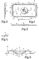
- Test card 20 (Fig. 1) includes an outer perimeter lip 21 which blends into integral tab 22 which is centered on the front edge 23 of the card.
- the test card 20 is shown to have a raised rib 24, uniformly inset from the outer perimeter edge, which extends approximately to 0.06 inches (1.52 mm) above top surface 25.
- the raised rib is uniformly inset such that the width of the perimeter lip is substantially the same throughout the perimeter of the test card with the noted exception of the front tab 22.
- test card 20 is also shown to have a tab 22 which provides an easy to use handle for convenience as well as to provide further safety to the operator as it keeps the fingers away from the possible contaminated surface within the rib area. In addition, this area can be used as a patient identification feature providing a place to write the patient's name.
- the center area of test card 20 (Fig. 1) includes a raised cylindrical portion 29 whose interior annular wall is uniquely shaped and contoured for this particular application. Portion 29 can be thought of as both a raised and recessed annular member which is hollow having opening 30 extending therethrough. With this description it is to be understood that opening 30 which is intended to denote the entire open area in the center of portion 29 has a varying diameter size as it extends from the larger top opening area to the smaller opening in the bottom surface.
- cylindrical portion 29 includes an outer vertical wall 31, top surface 32, double thickness folded lip 33, undercut annular recess 34, upper horizontal shelf 35, inner vertical wall 36 and lower horizontal shelf 37.
- the opening changes in diameter size as it extends from the top surface 32 to shelf 37 which defines centrally therein lower aperture 40.
- the structures of Figs. 5 and 12 are adapted to be fit or placed into a recessed area in the meter reading surface to receive the well portion and allowing for the tight optical alignment of the device which assists in increasing accuracy and precision of the results.
- portion 29 Another feature of portion 29 (Fig. 5) is that lower horizontal shelf 37 is disposed below top surface 25 of the main card. More specifically the upper surface 38 of shelf 37 is coincident with the underside 39 of top surface 25. Thus with a nominal material thickness of 0.02 inches (5.1 mm) for shelf 37, the lower surface of shelf 37 is approximately 0.02 inches (5.1 mm) below underside 39. This arrangement assures that the reagent area will be exposed to the measuring light beam when the device is placed in a meter. Although this nominal thickness has been found useful to form test cards, other thicknesses depending upon material composition can also be utilized.
- an inwardly beveled surface as viewed from the bottom may be formed at the peripheral edge of 37 to allow more light to be reflected from the reagent area.
- the shelf member 37 may also be spacially positioned differently with respect to the top surface 25.
- the outside diameter of portion 29 (Fig. 5) is approximately 0.94 inches (23.85 mm) and its height above underside 39 is approximately 0.12 inches (3.05 mm).
- the inside diameter of lip 33 is approximately 0.44 inches (11.18 mm) and the diameter of recess 34 is approximately 0.52 inches (13.21 mm). The result of these dimensions creates an overhang width for lip 33 of approximately 0.04 inches (1.02 mm). These latter dimensions are also exemplary and can be varied depending upon material composition and test card use.
- test card 20 (Fig. 1) is used as a receptacle or holder for a reagent chemistry pad which fits within opening 30 (Fig. 5). More specifically, the pad which is cylindrical so as to match the shape of the receiving pocket of portion 29 (Fig. 5) typically includes a plurality of laminations, in the illustrated embodiment there are three, and this reagent chemistry pad rests on surface 38 of shelf 37 and is flush with to slightly recessed below shelf 35. The reagent chemistry pad is captured by use of a snap-fit cover 43 as is illustrated in Figs. 6A, 6B and 7. Cover 43 is an annular ring or disc of uniform thickness with a main body 44 defined by an outer edge 45 and inner circular opening 46.
- Opening 46 (Figs. 6A and 6B) is shown to be coaxial with aperture 40 (Fig. 5).
- the opening 46 of cover 43 can also have a mesh or grid area 47, as illustrated in Fig. 6B.
- the mesh or grid area 47 may be formed integral with cover 43 or may be a separate structure subsequently fixed to cover 43.
- the grid area 47 is provided to impart a uniform retaining force to the reagent pad held in the opening or well 30.
- a pipette for example, having a quantity of sample drops a quantity of sample into contact with the filter/matrix 171-174 (Fig. 20). After absorption of the fluid sample added, a reaction takes place and the bottom layer of the matrix changes its color to show the existence of a predetermined chemical component, which is viewable through the bottom aperture 177.
- the color changes in the bottom layer of the filter/matrix 174 shows the qualitative existence of the specified chemical component in the sample.
- a quantitative measurement can then be effected by use of a color chart, as known in the art, having varying color bars or codes.
- the cover 43 is preferably constructed out of polystyrene and is sized and shaped to snap fit securely within undercut recess 34.
- the height or axial depth of recess 34 is approximately 0.025 inches (.64 mm) and cover 43 is approximately 0.02 inches (.51 mm) in thickness. Since the diameter of the recess is approximately .52 inches and the outer diameter of cover 43 is approximately .50 inches (12.7 mm), assembly without interference is, therefore, possible.
- the size of cover 43 must change accordingly to fit and snap into recess 34.
- cover 43 in lieu of a snap-fit is to include a thin layer of adhesive on the underside as a means of attachment to the test card.
- the adhesive thickness is approximately .005 inches and a suitable material is a 3MTM adhesive transfer tape 9469PC covered with a release liner on the exposed side.
- a disposable diagnostic test card 120 which is designed to receive a customer's specific reagent chemistry (see Figs. 15 and 20 for examples of typical reagent pads) and used with a reflectance-type meter (see Figs. 21 and 22). As will be explained further, the color change of the reagent chemistry pad when reacted with whole blood or other liquid is measured by the meter. A software algorithm within the meter electronics converts the remission reading to a user-meaningful concentration reading such as milligrams per deciliter (mg/dL).
- Test card 120 (Fig. 8) is preferably a single and unitary, injection molded or thermoformed plastic member, for example, which is generally rectangular and specifically contoured in order to provide various features.
- the nominal material starting thickness throughout the test card is approximately 0.02 inches (.51 mm) and the preferred material is polystyrene, although, as will be later discussed, other materials may also be utilized.
- Test card 120 includes an outer perimeter lip 121 which blends into integral tab 122 which is centered on the front edge 123 of the card. Uniformly inset from the outer perimeter edge is a raised rib 124 which extends approximately to 0.06 inches (1.52 mm) above top surface 125.
- the raised rib is uniformly inset such that the width of the perimeter lip is substantially the same throughout the perimeter of the test card with the noted exception of the front tab 122.
- the overall length of the test card is approximately 2.6-3.50 inches (66.0-88.9 mm) and the body width (without tab 122) is approximately 1.5-2.0 inches (38.1-50.8 mm).
- other card dimensions and sizes can also be utilized within the purview of this invention.
- the center area of test card 120 includes a raised cylindrical portion 129 which has a contoured and uniquely shaped interior wall (annular) surrounding and defining center opening 130.
- the annular wall of portion 129 has a number of surfaces, edges, bends and contours and is uniquely shaped to receive the chemistry reagent pad and an appropriate cover which is snapped over the cylindrical portion 129 in order to sandwich or retain the pad in position.
- portion 129 includes outer vertical wall 131, top surface 132, upper horizontal shelf 133, intermediate angled wall 134, intermediate horizontal 135, inner vertical wall 136 and lower horizontal shelf 137 which defines aperture 138.
- the lower horizontal shelf 137 of test card 120 is disposed below top surface 125 such that the top surface of shelf 137 is coincident or flush with the underside 139 of top surface 125.
- Wall 134 is angled or tapered outwardly from top to bottom at a 10 degree slant so as to be compatible with tapered side wall 144 of cover 140 (Fig. 14).
- a slightly different cover 140 (see Figs. 13 and 14) is used with card 120.
- Cover 140 which has a cylindrical shape includes an outer circular lip 141 and a raised cylindrical center portion 142 with a defined opening 143 therein.
- Portion 142 has a slightly (10 degrees) tapered side wall 144 which snaps into the area of portion 129 defined by wall 134 and shelf 135.
- the reagent chemistry pad (Figs. 15 or 20) fits in the area defined by wall 136 and shelf 137.
- the diameter and thickness of lip 141 is such that it fits snugly onto outer shelf 133 and intermediate shelf 135 and as assembled, the top surface of lip 141 is substantially flush with top surface 132.
- Opening 143 is coaxial with aperture 138.
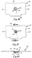
- Figs. 16-18 show another embodiment of the diagnostic device wherein the well structure 180 is shown positioned below the main planar body 179 of the card structure 178.
- the well structure 180 is positioned at a different height with respect to the horizontal plane of the card structure 178.
- the well structure 180 can be positioned at any vertical position with respect to the horizontal plane of the card structure 178.
- the bottom well aperture is located at a fixed position so that the reading path of the meter is aligned with each bottom well aperture so as to provide consistent and reliable results.
- a protruding card holding portion 186 is designed to be grasped by the user of the card structure 178 so as to avoid contamination and possible contact with a blood sample, for example, as well as to identify the patient and to place test results.
- the positioning slots 187 and 188 are utilized for proper placement of the card structure 178 into the holder of a diagnostic meter so that the card and consequently the bottom aperture 182 is properly aligned and positioned with respect the the reading path of the meter.
- a recessed area in the meter reading surface to accommodate the well shown in Fig. 18 can be used for alignment purposes.
- the female recesses or indentations are located peripherally about the optical apertures 163 on the flat surface 162 and would fix the well in position for subsequent reading.
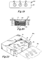
- Fig. 19 shows a test strip 189 having a planar body 193 with a plurality of well structures 190-192.
- diagnostic card structures have been shown and discussed, it is possible to utilize the teachings of this invention, particularly those pertaining to the well structures 190-192, in rigid or semi-rigid structures such as in elongated test strips.
- Fig. 20 shows an alternative embodiment of the system wherein the well enclosure 170 of body 194 has a plurality of layers or matrices 172-174 disposed therein between the retaining structure 171 with aperture 196 and the well bottom 176 with bottom aperture 177. Circumferential adjustment ridges 175, 197 and 198 are shown to extend inwardly from the well wall 195.
- This embodiment permits a variety of matrix compositions to be securely held within the well enclosure 170.
- the matrix 172-174 may consist of chemically impregnated papers, filters or membranes, or a combination thereof which are utilized to separate and/or react desired components of the blood or serum sample.
- test devices While specific embodiments for the test devices according to the present invention are disclosed, the general design, features and use are the same. The primary difference between the various embodiments is in the well structure configurations, design of the covers, how they snap into the central openings (pockets) of the test cards and the method in which the reagent pads are held in the annular receiving pocket which is part of the corresponding cylindrical portions.
- a typical reagent chemistry pad 150 is illustrated in Figs. 15 and 20 and includes a plurality of layers 150a, 150b, and 150c which are designed for the specific diagnostic test desired.
- the diagnostic device structures shown and discussed are preferably of a rigid to semi-rigid composition.
- the rigidity allows more precise placement of the device into the optical block of the meter, thereby, increasing the accuracy and precision of the results.
- Suitable compositions include plastics, particularly those which can be molded or thermoformed. These materials also include biodegradable plastics, cardboard and board/plastic laminations. Such compositions provide economically feasible structures which are disposable and which can be discarded after use.
- generally planar and rectilinear card structures are shown and have been described, other shapes of the device can be utilized to provide the function of the diagnostic device structures of this invention.
- the test card is shown to be similar in size to a business card (3.5 by 2.0 inches).
- the size of the card makes it easy to handle and the rounded corners prevent tearing of latex gloves.
- One card structure has been designed for use with a diagnostic meter. This card structure has specific dimensions and structure (compositions) suited for such use.
- alternative embodiments of the card structures are shown, for example, with multiple wells, or have structures for direct visualization and, thus, useable without a meter. Alternative embodiments do not necessarily require the specific dimensions set forth in these examples.
- the devices of the present invention may be utilized in conjunction with a reflectance-type meter. Initially the device is removed from its packaging and inserted into the meter. The meter takes a color reading of the unreacted chemical pad which is visible on the bottom of the device through the apertures in the lower shelf of the cylindrical center portion. Then, a drop of blood or other fluid sample is introduced onto the center portion of the cover such that it is allowed to freely flow through the opening in the cover onto the first lamination of the reagent chemistry pad. The chemical reaction with the laminations of the pad by the blood occur layer by layer from the top through to the bottom of the pad. The meter then takes another color reading of the reacted (colored) chemical pad. The difference between these two readings is converted into a user-meaningful concentration value.
- Reading errors are minimized because the disposable diagnostic device is securely positioned in the meter and is not removed when the blood is applied. By securely fixing the position of the test device within the meter and not allowing that position to shift or vary, any variations which might be introduced into the reading are reduced or eliminated.
- the configuration and size of the device also protects the meter from contamination by errant drops of samples, such as blood, serum, saliva or other body fluid. This reduces the need to clean and sterilize the reflectance-type meters and constitutes a significant advantage for end users such as hospitals and doctors' offices.
- the raised rib 24 (and 124) which extends about the perimeter of the respective test cards prevents blood drops from running off the edge of the card and, thus, reduces the risk of infection to the health care professionals involved in use of the present invention.
- the front flared tab on the card gives the card a definite visible orientation and provides the user with a positive grasping surface. Should the card, for example, be inserted backwards into the meter holder, the tab would prevent the card from seating properly therein.
- the bottom surface of the card below the reagent pads is designed to be slightly lower than the rest of the card. This offset assures intimate contact of the disposable test card with the meter optics despite any minor dimensional changes to the card due to the thermoforming process, for example. Intimate contact of the disposable test card with the meter optics increases the accuracy of the reading.
- the bottom of the well structure may also be disposed above, directly level with, or below the plane of the card surface, as is also shown, depending upon either the type of meter device or visualization method used.
- Positioning of the device in a meter can be achieved through card notches or indentations, as well as by the well or device protrusion.
- the well protrusion by itself can provide an excellent positioning feature of the device relative to the meter optics by utilizing a cooperating or mating surface in the meter.
- the device size and configuration allows room for bar code graphics to be printed on the underneath side of the device, for example.
- This bar code which is read by the meter during device insertion, may contain lot-specified data about the reagent chemistry. This data may further contain the critical parameters for the software algorithm within the meter electronics. Several glucose meters on the market today require the user to manually enter this data through entry buttons on the face of the meter.
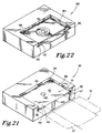
- meter 160 is illustrated without (Fig. 21) and with (Fig. 22) a test card inserted.
- the receiving portion 161 of the meter includes a substantially flat surface 162 with a centrally disposed glass covered aperture 163 which is the window through which the meter takes readings of the color change which occurs in the chemistry reagent pad.
- the outer edge of surface 162 is bounded by a raised wall 164 which includes an undercut channel 165 for receipt of perimeter lip 21 (and 121) of the corresponding test cards. It is to be understood that the thickness of the perimeter lip is closely sized with the height of undercut channel 165 for a free, yet closely sized sliding fit of the card into the meter.
- meter 160a includes three aligned and evenly spaced apertures 163a, 163b and 163c.
- Test card 20a illustrated in phantom line form includes a corresponding aligned and spaced series of raised portions 29a, 29b and 29c. This multiple design allows three tests or readings to be made at the same time, for example, by the insertion of a single test card.
Landscapes
- Health & Medical Sciences (AREA)
- Life Sciences & Earth Sciences (AREA)
- Immunology (AREA)
- Engineering & Computer Science (AREA)
- Chemical & Material Sciences (AREA)
- Hematology (AREA)
- Molecular Biology (AREA)
- Biomedical Technology (AREA)
- Urology & Nephrology (AREA)
- General Health & Medical Sciences (AREA)
- Analytical Chemistry (AREA)
- Medicinal Chemistry (AREA)
- Pathology (AREA)
- Food Science & Technology (AREA)
- Cell Biology (AREA)
- Physics & Mathematics (AREA)
- Biotechnology (AREA)
- Biochemistry (AREA)
- Microbiology (AREA)
- General Physics & Mathematics (AREA)
- Chemical Kinetics & Catalysis (AREA)
- Clinical Laboratory Science (AREA)
- Investigating Or Analysing Biological Materials (AREA)
- Hardware Redundancy (AREA)
- Use Of Switch Circuits For Exchanges And Methods Of Control Of Multiplex Exchanges (AREA)
- Detection And Prevention Of Errors In Transmission (AREA)
- Orthopedics, Nursing, And Contraception (AREA)
- Diaphragms For Electromechanical Transducers (AREA)
- External Artificial Organs (AREA)
Claims (28)
- Dispositif de test de diagnostique destiné à mesurer un analyte dans un échantillon comprenant:une structure de carte semi-rigide (20) de taille prédéterminée et ayant une configuration sensiblement plane et rectangulaire;au moins un puits en cuvette (30) solidaire et disposé dans cette structure étant positionné en un emplacement prédéterminé, ce puits en cuvette ayant une paroi (36) de profondeur prédéterminée, une portion de dessus (35) et un fond (37,38) avec des moyens (40) permettant la transmission d'un signal à travers le puits;des moyens de retenue (33,34) comportant une ouverture, ces moyens de retenue servant à fixer sur la portion de dessus (35) du puits en cuvette (30) et définissant un volume intérieur pour recevoir et retenir un élément de diagnostique, caractérisé par une structure à nervures profilées (24,124) formée solidairement sur la surface de dessus du et s'étendant sur le périmètre de la structure de carte semi-rigide.
- Dispositif de test de diagnostique selon la revendication 1, dans lequel la structure semi-rigide (20) présente une configuration plane horizontale et dans lequel la paroi du puits en cuvette (36) venant en intersection dans le plan horizontal de la structure.
- Dispositif de test de diagnostique selon la revendication 1, dans lequel la structure semi-rigide (20) a une configuration plane horizontale et dans lequel la paroi du puits en cuvette (36) est positionnée au-dessus du plan horizontal de la structure.
- Dispositif de test de diagnostique selon la revendication 1, dans lequel la structure semi-rigide a une configuration plane horizontale et dans lequel la paroi du puits en cuvette (36) est positionnée au-dessous du plan horizontal de la structure.
- Dispositif de test de diagnostique selon l'une quelconque des revendications précédentes, dans lequel la portion de dessus du puits en cuvette (35) comporte une gorge circonférentielle, et dans lequel le moyen de retenue (33,34) est un couvercle à encliquetage et présente une configuration pour s'engager par friction dans la gorge circonférentielle.
- Dispositif de test de diagnostique selon l'une quelconque des revendications précédentes, dans lequel la structure semi-rigide comporte un moyen d'alignement passif (21) formé solidairement dans celui-ci, ce moyen comprenant au moins une encoche en un endroit périphérique prédéterminé de la structure.
- Dispositif de test de diagnostique selon l'une quelconque des revendications précédentes, dans lequel le puits en cuvette est conçu et disposé de façon à fournir un moyen d'alignement passif pour la structure destinée à l'utilisation dans un compteur.
- Dispositif de test de diagnostique selon la revendication 1, dans lequel la structure a une configuration rectangulaire et présente les dimensions extérieures d'une carte semi-rigide.
- Dispositif de test de diagnostique selon l'une quelconque des revendications précédentes, dans lequel le moyen de retenue (33,34) comporte de plus une structure de grille (47) recouvrant l'ouverture.
- Dispositif de test de diagnostique selon l'une quelconque des revendications précédentes, dans lequel la structure semi-rigide est une bande allongée.
- Dispositif de test de diagnostique selon l'une quelconque des revendications précédentes, dans lequel la structure semi-rigide comporte plusieurs puits en cuvette (190-192) formés dans celle-ci, chaque puits ayant une structure de retenue.
- Dispositif de test de diagnostique selon la revendication 11, dans lequel l'un de ces puits contient un réactif chimique d'essai.
- Dispositif de test de diagnostique selon l'une quelconque des revendications précédentes, dans lequel la structure semi-rigide (20) comporte des informations.
- Dispositif de test de diagnostique selon la revendication 13, dans lequel les informations comprennent des données du groupe constitué par un code à bâtonnets, des données d'étalonnage de compteur test, le nom du patient, le nom du responsable du test et une identification du lot chimique.
- Dispositif de test de diagnostique selon l'une quelconque des revendications précédentes, dans lequel le moyen (40) permettant la transmission d'un signal comprend une ouverture dans le fond du puits en cuvette.
- Dispositif de test de diagnostique selon la revendication 15, dans lequel le fond du puits comporte une fenêtre transparente recouvrant l'ouverture.
- Dispositif de test de diagnostique selon l'une quelconque des revendications précédentes, dans lequel le moyen (40) qui permet la transmission d'un signal comprend une zone sensiblement transparente dans le fond du puits en cuvette.
- Dispositif de test de diagnostique selon l'une quelconque des revendications précédentes, dans lequel la paroi du puits (36) comporte au moins un rebord faisant circonférentiellement saillie, (35) positionné spatialement par rapport au fond du puits.
- Dispositif de test de diagnostique selon la revendication 18, dans lequel la paroi du puits (36) comporte plusieurs rebords circonférentiels spatialement parallèles, le moyen de retenue comportant de plus un bord périphérique pour la mise en place entre les rebords contigus de façon à fournir une profondeur de puits réglable et recevoir une plage d'épaisseur de matrice.
- Dispositif de test de diagnostique selon la revendication 19, dans lequel une pluralité de matrices (172-174) est positionnée dans le puits en cuvette dans une configuration stratifiée.
- Dispositif de test de diagnostique selon l'une quelconque des revendications précédentes, comprenant de plus un élément de diagnostique, cet élément de diagnostique étant destiné à faire réagir l'échantillon et à produire un signal de sortie correspondant à la concentration d'analyte, cet élément de diagnostique comprenant au moins une matrice.
- Dispositif de test de diagnostique selon la revendication 21, dans lequel la matrice comprend au moins une couche d'imprégnation chimique.
- Dispositif de test de diagnostique selon la revendication 21 ou 22, dans lequel la matrice assure une réaction enzymatique lors du contact avec l'échantillon pour la détection de la mesure quantitative de l'analyte.
- Dispositif de test de diagnostique selon l'une quelconque des revendications 21-23, dans lequel la matrice fournit une réaction immunochimique lors du contact avec l'échantillon pour la détection de la mesure quantitative d'un analyte.
- Dispositif de test de diagnostique selon l'une quelconque des revendications 21-24, dans lequel la matrice comprend au moins une couche filtre et au moins une couche d'imprégnation chimique qui est disposée entre la couche filtre et le fond du puits.
- Système de test de diagnostique comprenant un compteur optique avec des moyens pour recevoir un dispositif de test selon l'une quelconque des revendications 21 à 23, et un algorithme de logiciel pour fournir une valeur de concentration d'analyte significative pour l'utilisateur par l'intermédiaire d'un signal provenant d'un élément de diagnostique ayant réagi, fourni sur le dispositif de test.
- Système de test de diagnostique selon la revendication 26, dans lequel le système comprend de plus une carte couleur comportant une pluralité de codes à bâtonnets couleur correspondant à une plage de valeurs de concentration d'analyte, cette carte couleur étant visuellement comparable à l'élément de diagnostique ayant réagi par l'intermédiaire du moyen de transmission de signal.
- Système de test de diagnostique selon l'une quelconque des revendications 26 ou 27, dans lequel la structure semi-rigide comporte un axe géométrique central et dans lequel au moins un puits en cuvette (30) est solidaire et disposé verticalement dans la structure semi-rigide et positionné le long de son axe géométrique central.
Applications Claiming Priority (5)
| Application Number | Priority Date | Filing Date | Title |
|---|---|---|---|
| US46992090A | 1990-01-24 | 1990-01-24 | |
| US469920 | 1990-01-24 | ||
| US07/628,348 US5104619A (en) | 1990-01-24 | 1990-12-17 | Disposable diagnostic system |
| US628348 | 1990-12-17 | ||
| PCT/US1991/000289 WO1991011700A1 (fr) | 1990-01-24 | 1991-01-15 | Systeme de diagnostic jetable |
Publications (3)
| Publication Number | Publication Date |
|---|---|
| EP0512059A1 EP0512059A1 (fr) | 1992-11-11 |
| EP0512059A4 EP0512059A4 (en) | 1993-09-08 |
| EP0512059B1 true EP0512059B1 (fr) | 1996-06-12 |
Family
ID=27042896
Family Applications (1)
| Application Number | Title | Priority Date | Filing Date |
|---|---|---|---|
| EP91904217A Expired - Lifetime EP0512059B1 (fr) | 1990-01-24 | 1991-01-15 | Systeme de diagnostic jetable |
Country Status (6)
| Country | Link |
|---|---|
| US (1) | US5104619A (fr) |
| EP (1) | EP0512059B1 (fr) |
| AT (1) | ATE139340T1 (fr) |
| AU (1) | AU7253491A (fr) |
| DE (1) | DE69120255D1 (fr) |
| WO (1) | WO1991011700A1 (fr) |
Families Citing this family (114)
| Publication number | Priority date | Publication date | Assignee | Title |
|---|---|---|---|---|
| US4935346A (en) * | 1986-08-13 | 1990-06-19 | Lifescan, Inc. | Minimum procedure system for the determination of analytes |
| US6352863B1 (en) | 1990-01-19 | 2002-03-05 | La Mina, Inc. | Assay device |
| DE4012216A1 (de) * | 1990-04-14 | 1991-10-17 | Boehringer Mannheim Gmbh | Testtraeger fuer die analyse von fluessigkeiten |
| CA2062027C (fr) * | 1991-03-04 | 1998-05-19 | William Aldrich | Systeme de controle du liquide pour cartouches de diagnostic utilisees dans des instruments d'analyse |
| US5686315A (en) * | 1991-06-14 | 1997-11-11 | Quidel Corporation | Assay device for one step detection of analyte |
| JP3314099B2 (ja) * | 1993-02-26 | 2002-08-12 | ジャパン メンブレン テクノロジー株式会社 | フィルターとその製造方法ならびにその使用方法 |
| US5837546A (en) * | 1993-08-24 | 1998-11-17 | Metrika, Inc. | Electronic assay device and method |
| JP2810238B2 (ja) * | 1993-11-12 | 1998-10-15 | ユニパス・リミテツド | 検定装置およびその製造 |
| US5597532A (en) * | 1994-10-20 | 1997-01-28 | Connolly; James | Apparatus for determining substances contained in a body fluid |
| US5728352A (en) * | 1994-11-14 | 1998-03-17 | Advanced Care Products | Disposable electronic diagnostic instrument |
| US7635597B2 (en) | 1995-08-09 | 2009-12-22 | Bayer Healthcare Llc | Dry reagent particle assay and device having multiple test zones and method therefor |
| US5962215A (en) | 1996-04-05 | 1999-10-05 | Mercury Diagnostics, Inc. | Methods for testing the concentration of an analyte in a body fluid |
| US6165335A (en) | 1996-04-25 | 2000-12-26 | Pence And Mcgill University | Biosensor device and method |
| US5945341A (en) * | 1996-10-21 | 1999-08-31 | Bayer Corporation | System for the optical identification of coding on a diagnostic test strip |
| US20050101032A1 (en) * | 1997-02-10 | 2005-05-12 | Metrika, Inc. | Assay device, composition, and method of optimizing assay sensitivity |
| US6036924A (en) | 1997-12-04 | 2000-03-14 | Hewlett-Packard Company | Cassette of lancet cartridges for sampling blood |
| US6391005B1 (en) | 1998-03-30 | 2002-05-21 | Agilent Technologies, Inc. | Apparatus and method for penetration with shaft having a sensor for sensing penetration depth |
| US20060019404A1 (en) * | 1998-05-06 | 2006-01-26 | Blatt Joel M | Quantitative assay with extended dynamic range |
| US6787368B1 (en) | 1999-03-02 | 2004-09-07 | Helix Biopharma Corporation | Biosensor method for detecting analytes in a liquid |
| US6136549A (en) * | 1999-10-15 | 2000-10-24 | Feistel; Christopher C. | systems and methods for performing magnetic chromatography assays |
| US6458326B1 (en) | 1999-11-24 | 2002-10-01 | Home Diagnostics, Inc. | Protective test strip platform |
| US8641644B2 (en) | 2000-11-21 | 2014-02-04 | Sanofi-Aventis Deutschland Gmbh | Blood testing apparatus having a rotatable cartridge with multiple lancing elements and testing means |
| US6524864B2 (en) | 2000-12-28 | 2003-02-25 | Aurora L. Fernandez Decastro | Test strip for simultaneous detection of a plurality of analytes |
| US6541266B2 (en) | 2001-02-28 | 2003-04-01 | Home Diagnostics, Inc. | Method for determining concentration of an analyte in a test strip |
| US6525330B2 (en) | 2001-02-28 | 2003-02-25 | Home Diagnostics, Inc. | Method of strip insertion detection |
| ES2335576T3 (es) | 2001-06-12 | 2010-03-30 | Pelikan Technologies Inc. | Aparato y procedimiento de toma de muestras de sangre. |
| AU2002348683A1 (en) | 2001-06-12 | 2002-12-23 | Pelikan Technologies, Inc. | Method and apparatus for lancet launching device integrated onto a blood-sampling cartridge |
| US7344507B2 (en) | 2002-04-19 | 2008-03-18 | Pelikan Technologies, Inc. | Method and apparatus for lancet actuation |
| US9226699B2 (en) | 2002-04-19 | 2016-01-05 | Sanofi-Aventis Deutschland Gmbh | Body fluid sampling module with a continuous compression tissue interface surface |
| WO2002100460A2 (fr) | 2001-06-12 | 2002-12-19 | Pelikan Technologies, Inc. | Actionneur electrique de lancette |
| EP1406537B1 (fr) | 2001-06-12 | 2011-01-12 | Pelikan Technologies Inc. | Systeme integre de prelevement et d'analyse d'echantillons sanguins avec module de prelevement a utilisation multiple |
| US7981056B2 (en) | 2002-04-19 | 2011-07-19 | Pelikan Technologies, Inc. | Methods and apparatus for lancet actuation |
| US9795747B2 (en) | 2010-06-02 | 2017-10-24 | Sanofi-Aventis Deutschland Gmbh | Methods and apparatus for lancet actuation |
| CA2448902C (fr) | 2001-06-12 | 2010-09-07 | Pelikan Technologies, Inc. | Autopiqueur a optimisation automatique presentant des moyens d'adaptation aux variations temporelles des proprietes cutanees |
| ATE497731T1 (de) | 2001-06-12 | 2011-02-15 | Pelikan Technologies Inc | Gerät zur erhöhung der erfolgsrate im hinblick auf die durch einen fingerstich erhaltene blutausbeute |
| US7025774B2 (en) | 2001-06-12 | 2006-04-11 | Pelikan Technologies, Inc. | Tissue penetration device |
| US8337419B2 (en) | 2002-04-19 | 2012-12-25 | Sanofi-Aventis Deutschland Gmbh | Tissue penetration device |
| US6576416B2 (en) * | 2001-06-19 | 2003-06-10 | Lifescan, Inc. | Analyte measurement device and method of use |
| US7344894B2 (en) | 2001-10-16 | 2008-03-18 | Agilent Technologies, Inc. | Thermal regulation of fluidic samples within a diagnostic cartridge |
| US7232451B2 (en) | 2002-04-19 | 2007-06-19 | Pelikan Technologies, Inc. | Method and apparatus for penetrating tissue |
| US7524293B2 (en) | 2002-04-19 | 2009-04-28 | Pelikan Technologies, Inc. | Method and apparatus for penetrating tissue |
| US7141058B2 (en) | 2002-04-19 | 2006-11-28 | Pelikan Technologies, Inc. | Method and apparatus for a body fluid sampling device using illumination |
| US7674232B2 (en) | 2002-04-19 | 2010-03-09 | Pelikan Technologies, Inc. | Method and apparatus for penetrating tissue |
| US7717863B2 (en) | 2002-04-19 | 2010-05-18 | Pelikan Technologies, Inc. | Method and apparatus for penetrating tissue |
| US7547287B2 (en) | 2002-04-19 | 2009-06-16 | Pelikan Technologies, Inc. | Method and apparatus for penetrating tissue |
| US8702624B2 (en) | 2006-09-29 | 2014-04-22 | Sanofi-Aventis Deutschland Gmbh | Analyte measurement device with a single shot actuator |
| US7892183B2 (en) | 2002-04-19 | 2011-02-22 | Pelikan Technologies, Inc. | Method and apparatus for body fluid sampling and analyte sensing |
| US7491178B2 (en) | 2002-04-19 | 2009-02-17 | Pelikan Technologies, Inc. | Method and apparatus for penetrating tissue |
| US7976476B2 (en) | 2002-04-19 | 2011-07-12 | Pelikan Technologies, Inc. | Device and method for variable speed lancet |
| US7371247B2 (en) | 2002-04-19 | 2008-05-13 | Pelikan Technologies, Inc | Method and apparatus for penetrating tissue |
| US8267870B2 (en) | 2002-04-19 | 2012-09-18 | Sanofi-Aventis Deutschland Gmbh | Method and apparatus for body fluid sampling with hybrid actuation |
| US7901362B2 (en) | 2002-04-19 | 2011-03-08 | Pelikan Technologies, Inc. | Method and apparatus for penetrating tissue |
| US8784335B2 (en) | 2002-04-19 | 2014-07-22 | Sanofi-Aventis Deutschland Gmbh | Body fluid sampling device with a capacitive sensor |
| US7297122B2 (en) | 2002-04-19 | 2007-11-20 | Pelikan Technologies, Inc. | Method and apparatus for penetrating tissue |
| US8360992B2 (en) | 2002-04-19 | 2013-01-29 | Sanofi-Aventis Deutschland Gmbh | Method and apparatus for penetrating tissue |
| US7713214B2 (en) | 2002-04-19 | 2010-05-11 | Pelikan Technologies, Inc. | Method and apparatus for a multi-use body fluid sampling device with optical analyte sensing |
| US8221334B2 (en) | 2002-04-19 | 2012-07-17 | Sanofi-Aventis Deutschland Gmbh | Method and apparatus for penetrating tissue |
| US7291117B2 (en) | 2002-04-19 | 2007-11-06 | Pelikan Technologies, Inc. | Method and apparatus for penetrating tissue |
| US9795334B2 (en) | 2002-04-19 | 2017-10-24 | Sanofi-Aventis Deutschland Gmbh | Method and apparatus for penetrating tissue |
| US7892185B2 (en) | 2002-04-19 | 2011-02-22 | Pelikan Technologies, Inc. | Method and apparatus for body fluid sampling and analyte sensing |
| US9314194B2 (en) | 2002-04-19 | 2016-04-19 | Sanofi-Aventis Deutschland Gmbh | Tissue penetration device |
| US7331931B2 (en) | 2002-04-19 | 2008-02-19 | Pelikan Technologies, Inc. | Method and apparatus for penetrating tissue |
| US7229458B2 (en) | 2002-04-19 | 2007-06-12 | Pelikan Technologies, Inc. | Method and apparatus for penetrating tissue |
| US8579831B2 (en) | 2002-04-19 | 2013-11-12 | Sanofi-Aventis Deutschland Gmbh | Method and apparatus for penetrating tissue |
| US7582099B2 (en) | 2002-04-19 | 2009-09-01 | Pelikan Technologies, Inc | Method and apparatus for penetrating tissue |
| US7909778B2 (en) | 2002-04-19 | 2011-03-22 | Pelikan Technologies, Inc. | Method and apparatus for penetrating tissue |
| US7648468B2 (en) | 2002-04-19 | 2010-01-19 | Pelikon Technologies, Inc. | Method and apparatus for penetrating tissue |
| US7265881B2 (en) * | 2002-12-20 | 2007-09-04 | Hewlett-Packard Development Company, L.P. | Method and apparatus for measuring assembly and alignment errors in sensor assemblies |
| US8574895B2 (en) | 2002-12-30 | 2013-11-05 | Sanofi-Aventis Deutschland Gmbh | Method and apparatus using optical techniques to measure analyte levels |
| DE602004028463D1 (de) | 2003-05-30 | 2010-09-16 | Pelikan Technologies Inc | Verfahren und vorrichtung zur injektion von flüssigkeit |
| WO2004107964A2 (fr) | 2003-06-06 | 2004-12-16 | Pelikan Technologies, Inc. | Procede et appareil d'echantillonnage de fluides anatomiques et d'examen de l'analysat |
| WO2006001797A1 (fr) | 2004-06-14 | 2006-01-05 | Pelikan Technologies, Inc. | Element penetrant peu douloureux |
| EP1635700B1 (fr) | 2003-06-13 | 2016-03-09 | Sanofi-Aventis Deutschland GmbH | Appareil pour dispositif d'analyse sur le lieu de soin |
| US8282576B2 (en) | 2003-09-29 | 2012-10-09 | Sanofi-Aventis Deutschland Gmbh | Method and apparatus for an improved sample capture device |
| US9351680B2 (en) | 2003-10-14 | 2016-05-31 | Sanofi-Aventis Deutschland Gmbh | Method and apparatus for a variable user interface |
| US8394337B2 (en) | 2003-12-31 | 2013-03-12 | Nipro Diagnostics, Inc. | Test strip container with integrated meter |
| US8394328B2 (en) * | 2003-12-31 | 2013-03-12 | Nipro Diagnostics, Inc. | Test strip container with integrated meter having strip coding capability |
| EP1706026B1 (fr) | 2003-12-31 | 2017-03-01 | Sanofi-Aventis Deutschland GmbH | Procédé et appareil permettant d'améliorer le flux fluidique et le prélèvement d'échantillons |
| US7822454B1 (en) | 2005-01-03 | 2010-10-26 | Pelikan Technologies, Inc. | Fluid sampling device with improved analyte detecting member configuration |
| US8147426B2 (en) | 2003-12-31 | 2012-04-03 | Nipro Diagnostics, Inc. | Integrated diagnostic test system |
| US9012232B2 (en) * | 2005-07-15 | 2015-04-21 | Nipro Diagnostics, Inc. | Diagnostic strip coding system and related methods of use |
| US7150995B2 (en) * | 2004-01-16 | 2006-12-19 | Metrika, Inc. | Methods and systems for point of care bodily fluid analysis |
| US8465696B2 (en) * | 2004-02-03 | 2013-06-18 | Polymer Technology Systems, Inc. | Dry test strip with controlled flow and method of manufacturing same |
| US7625721B2 (en) * | 2004-02-03 | 2009-12-01 | Polymer Technology Systems, Inc. | Non-precipitating bodily fluid analysis system |
| US20050227370A1 (en) * | 2004-03-08 | 2005-10-13 | Ramel Urs A | Body fluid analyte meter & cartridge system for performing combined general chemical and specific binding assays |
| WO2006011062A2 (fr) | 2004-05-20 | 2006-02-02 | Albatros Technologies Gmbh & Co. Kg | Hydrogel imprimable pour biocapteurs |
| US9775553B2 (en) | 2004-06-03 | 2017-10-03 | Sanofi-Aventis Deutschland Gmbh | Method and apparatus for a fluid sampling device |
| WO2005120365A1 (fr) | 2004-06-03 | 2005-12-22 | Pelikan Technologies, Inc. | Procede et appareil pour la fabrication d'un dispositif d'echantillonnage de liquides |
| DE102004036474A1 (de) * | 2004-07-28 | 2006-03-23 | Roche Diagnostics Gmbh | Analysesystem zur Analyse einer Probe auf einem Testelement |
| US20060062690A1 (en) * | 2004-08-17 | 2006-03-23 | Polymer Technology Systems, Inc. | Apparatus and method of manufacturing bodily fluid test strip |
| US8652831B2 (en) | 2004-12-30 | 2014-02-18 | Sanofi-Aventis Deutschland Gmbh | Method and apparatus for analyte measurement test time |
| US20060275890A1 (en) * | 2005-06-06 | 2006-12-07 | Home Diagnostics, Inc. | Method of manufacturing a disposable diagnostic meter |
| US8999125B2 (en) | 2005-07-15 | 2015-04-07 | Nipro Diagnostics, Inc. | Embedded strip lot autocalibration |
| US7955856B2 (en) * | 2005-07-15 | 2011-06-07 | Nipro Diagnostics, Inc. | Method of making a diagnostic test strip having a coding system |
| US7889347B2 (en) * | 2005-11-21 | 2011-02-15 | Plexera Llc | Surface plasmon resonance spectrometer with an actuator driven angle scanning mechanism |
| US7463358B2 (en) * | 2005-12-06 | 2008-12-09 | Lumera Corporation | Highly stable surface plasmon resonance plates, microarrays, and methods |
| US7879623B2 (en) * | 2006-03-31 | 2011-02-01 | Guirguis Raouf A | Integrated device for analyte, testing, confirmation, and donor identity verification |
| US7741103B2 (en) * | 2006-03-31 | 2010-06-22 | Guirguis Raouf A | Integrated screening and confirmation device |
| US11906512B2 (en) | 2006-03-31 | 2024-02-20 | Zeus Diagnostics, LLC | Integrated device for analyte testing, confirmation, and donor identity verification |
| US8940527B2 (en) * | 2006-03-31 | 2015-01-27 | Lamina Equities Corp. | Integrated device for analyte testing, confirmation, and donor identity verification |
| US20080020452A1 (en) * | 2006-07-18 | 2008-01-24 | Natasha Popovich | Diagnostic strip coding system with conductive layers |
| US20090060786A1 (en) * | 2007-08-29 | 2009-03-05 | Gibum Kim | Microfluidic apparatus for wide area microarrays |
| US20090104635A1 (en) * | 2007-10-19 | 2009-04-23 | Tom Cheng Xu | Fluorescent Dry Test Strip Biosensor |
| US8004669B1 (en) | 2007-12-18 | 2011-08-23 | Plexera Llc | SPR apparatus with a high performance fluid delivery system |
| EP2265324B1 (fr) | 2008-04-11 | 2015-01-28 | Sanofi-Aventis Deutschland GmbH | Système intégré de mesure d'analytes |
| US20110200498A1 (en) * | 2008-06-17 | 2011-08-18 | Polymer Technology Systems, Inc. | System and method for packaging dry test strips |
| US9375169B2 (en) | 2009-01-30 | 2016-06-28 | Sanofi-Aventis Deutschland Gmbh | Cam drive for managing disposable penetrating member actions with a single motor and motor and control system |
| US8965476B2 (en) | 2010-04-16 | 2015-02-24 | Sanofi-Aventis Deutschland Gmbh | Tissue penetration device |
| US10114020B2 (en) | 2010-10-11 | 2018-10-30 | Mbio Diagnostics, Inc. | System and device for analyzing a fluidic sample |
| WO2014012558A2 (fr) * | 2012-07-20 | 2014-01-23 | Lattec I/S | Dispositif de bâtonnet sec et procédé de détermination d'une substance à analyser dans un échantillon |
| WO2014070235A1 (fr) | 2012-10-29 | 2014-05-08 | Mbio Diagnostics, Inc. | Système d'identification de particules biologiques, cartouche et procédés associés |
| US10564155B2 (en) | 2017-01-27 | 2020-02-18 | Raouf A Guirguis | Dual swab fluid sample collection for split sample testing and fingerprint identification device |
| WO2019050837A1 (fr) * | 2017-09-06 | 2019-03-14 | Clemson University Research Foundation | Conception de coupon à sensibilité de couleur améliorée pour analyse chimique de liquides basée sur la colorimétrie |
| KR102210306B1 (ko) * | 2018-08-28 | 2021-02-09 | (주)인트인 | 체액 분석용 검사 장치 |
Family Cites Families (8)
| Publication number | Priority date | Publication date | Assignee | Title |
|---|---|---|---|---|
| US4365970A (en) * | 1981-05-01 | 1982-12-28 | Smithkline Instruments, Inc. | Specimen test slide and method for testing occult blood |
| DE3133826A1 (de) * | 1981-08-27 | 1983-03-10 | Boehringer Mannheim Gmbh, 6800 Mannheim | Analyseteststreifen und verfahren zu seiner herstellung |
| DE3530993A1 (de) * | 1985-08-30 | 1987-03-05 | Miles Lab | Teststreifen mit festlegbarer probenaufnahmekapazitaet |
| US4916056A (en) * | 1986-02-18 | 1990-04-10 | Abbott Laboratories | Solid-phase analytical device and method for using same |
| US4797260A (en) * | 1987-01-27 | 1989-01-10 | V-Tech, Inc. | Antibody testing system |
| US4912034A (en) * | 1987-09-21 | 1990-03-27 | Biogenex Laboratories | Immunoassay test device and method |
| US4818677A (en) * | 1987-12-03 | 1989-04-04 | Monoclonal Antibodies, Inc. | Membrane assay using focused sample application |
| IL96887A (en) * | 1991-01-06 | 1996-08-04 | Orgenics Ltd | Apparatus for dry chemical analysis of fluids |
-
1990
- 1990-12-17 US US07/628,348 patent/US5104619A/en not_active Expired - Lifetime
-
1991
- 1991-01-15 WO PCT/US1991/000289 patent/WO1991011700A1/fr active IP Right Grant
- 1991-01-15 AT AT91904217T patent/ATE139340T1/de not_active IP Right Cessation
- 1991-01-15 AU AU72534/91A patent/AU7253491A/en not_active Abandoned
- 1991-01-15 DE DE69120255T patent/DE69120255D1/de not_active Expired - Lifetime
- 1991-01-15 EP EP91904217A patent/EP0512059B1/fr not_active Expired - Lifetime
Also Published As
| Publication number | Publication date |
|---|---|
| EP0512059A1 (fr) | 1992-11-11 |
| ATE139340T1 (de) | 1996-06-15 |
| DE69120255D1 (de) | 1996-07-18 |
| AU7253491A (en) | 1991-08-21 |
| EP0512059A4 (en) | 1993-09-08 |
| US5104619A (en) | 1992-04-14 |
| WO1991011700A1 (fr) | 1991-08-08 |
Similar Documents
| Publication | Publication Date | Title |
|---|---|---|
| EP0512059B1 (fr) | Systeme de diagnostic jetable | |
| AU2008318717B2 (en) | Method and apparatus for coding diagnostic meters | |
| US6176119B1 (en) | Analytical system for sample liquids | |
| CA1206078A (fr) | Reactifs auto-empilables | |
| AU712523B2 (en) | Analyte concentration measurement using a hollow frustum | |
| EP1359418B1 (fr) | Dispositif et méthode pour déterminer la concentration des analytes | |
| EP0128422B1 (fr) | Support pour bandes-test | |
| EP1359419A1 (fr) | Dispositif et méthode pour la détermination de la concentration des analytes | |
| EP0451981A2 (fr) | Unité réactive à jeter après usage | |
| US20030195435A1 (en) | Method and apparatus for collecting and transporting capillary blood samples for diagnostic and research evaluation | |
| AU3596595A (en) | Test strip with an asymmetrical end insuring correct insertion for measuring | |
| CA2212476A1 (fr) | Appareil de mesure de dosage a distance de la concentration d'un analyte | |
| MXPA03000334A (es) | Recipiente distribuidor de tiras de prueba. | |
| CN1162359A (zh) | 具有定向索引区的用于分析物检测的光学可读片条 | |
| CN106662573B (zh) | 用于确定尿液中的分析物和/或化学-物理参数、以及确定尿液中尿沉淀的容器;以及使用该容器进行全尿分析的方法 | |
| WO1993003673A1 (fr) | Unite de reactif jetable avec protection contre la contamination par le sang ou autre liquide biologique | |
| US20070059678A1 (en) | Breast milk contaminant detection device | |
| CA2067724C (fr) | Dispositif jetable pour diagnostic | |
| US6418606B1 (en) | Method of manufacturing an assaying device | |
| US6010663A (en) | Die cut reagent membrane, holder | |
| EP1298437B1 (fr) | Dispositif d'essai colorimétrique avec taux d'erreur réduit | |
| US20030232451A1 (en) | Device for the testing of fluid samples and process for making the device | |
| US20040184965A1 (en) | Testing cup | |
| US11559810B2 (en) | Method and apparatus for coding diagnostic meters |
Legal Events
| Date | Code | Title | Description |
|---|---|---|---|
| PUAI | Public reference made under article 153(3) epc to a published international application that has entered the european phase |
Free format text: ORIGINAL CODE: 0009012 |
|
| 17P | Request for examination filed |
Effective date: 19920519 |
|
| AK | Designated contracting states |
Kind code of ref document: A1 Designated state(s): AT BE CH DE DK ES FR GB GR IT LI LU NL SE |
|
| A4 | Supplementary search report drawn up and despatched |
Effective date: 19930723 |
|
| AK | Designated contracting states |
Kind code of ref document: A4 Designated state(s): AT BE CH DE DK ES FR GB GR IT LI LU NL SE |
|
| 17Q | First examination report despatched |
Effective date: 19950214 |
|
| GRAH | Despatch of communication of intention to grant a patent |
Free format text: ORIGINAL CODE: EPIDOS IGRA |
|
| GRAH | Despatch of communication of intention to grant a patent |
Free format text: ORIGINAL CODE: EPIDOS IGRA |
|
| GRAA | (expected) grant |
Free format text: ORIGINAL CODE: 0009210 |
|
| AK | Designated contracting states |
Kind code of ref document: B1 Designated state(s): AT BE CH DE DK ES FR GB GR IT LI LU NL SE |
|
| PG25 | Lapsed in a contracting state [announced via postgrant information from national office to epo] |
Ref country code: IT Free format text: LAPSE BECAUSE OF FAILURE TO SUBMIT A TRANSLATION OF THE DESCRIPTION OR TO PAY THE FEE WITHIN THE PRE;WARNING: LAPSES OF ITALIAN PATENTS WITH EFFECTIVE DATE BEFORE 2007 MAY HAVE OCCURRED AT ANY TIME BEFORE 2007. THE CORRECT EFFECTIVE DATE MAY BE DIFFERENT FROM THE ONE RECORDED.SCRIBED TIME-LIMIT Effective date: 19960612 Ref country code: FR Effective date: 19960612 Ref country code: LI Effective date: 19960612 Ref country code: GR Free format text: LAPSE BECAUSE OF FAILURE TO SUBMIT A TRANSLATION OF THE DESCRIPTION OR TO PAY THE FEE WITHIN THE PRESCRIBED TIME-LIMIT Effective date: 19960612 Ref country code: ES Free format text: THE PATENT HAS BEEN ANNULLED BY A DECISION OF A NATIONAL AUTHORITY Effective date: 19960612 Ref country code: CH Effective date: 19960612 Ref country code: DK Effective date: 19960612 Ref country code: BE Effective date: 19960612 Ref country code: NL Free format text: LAPSE BECAUSE OF FAILURE TO SUBMIT A TRANSLATION OF THE DESCRIPTION OR TO PAY THE FEE WITHIN THE PRESCRIBED TIME-LIMIT Effective date: 19960612 Ref country code: AT Effective date: 19960612 |
|
| REF | Corresponds to: |
Ref document number: 139340 Country of ref document: AT Date of ref document: 19960615 Kind code of ref document: T |
|
| REF | Corresponds to: |
Ref document number: 69120255 Country of ref document: DE Date of ref document: 19960718 |
|
| PG25 | Lapsed in a contracting state [announced via postgrant information from national office to epo] |
Ref country code: SE Effective date: 19960912 |
|
| PG25 | Lapsed in a contracting state [announced via postgrant information from national office to epo] |
Ref country code: DE Effective date: 19960913 |
|
| NLV1 | Nl: lapsed or annulled due to failure to fulfill the requirements of art. 29p and 29m of the patents act | ||
| EN | Fr: translation not filed | ||
| REG | Reference to a national code |
Ref country code: CH Ref legal event code: PL |
|
| PG25 | Lapsed in a contracting state [announced via postgrant information from national office to epo] |
Ref country code: LU Free format text: LAPSE BECAUSE OF NON-PAYMENT OF DUE FEES Effective date: 19970131 |
|
| PLBE | No opposition filed within time limit |
Free format text: ORIGINAL CODE: 0009261 |
|
| STAA | Information on the status of an ep patent application or granted ep patent |
Free format text: STATUS: NO OPPOSITION FILED WITHIN TIME LIMIT |
|
| 26N | No opposition filed | ||
| REG | Reference to a national code |
Ref country code: GB Ref legal event code: IF02 |
|
| PGFP | Annual fee paid to national office [announced via postgrant information from national office to epo] |
Ref country code: GB Payment date: 20020116 Year of fee payment: 12 |
|
| PG25 | Lapsed in a contracting state [announced via postgrant information from national office to epo] |
Ref country code: GB Free format text: LAPSE BECAUSE OF NON-PAYMENT OF DUE FEES Effective date: 20030115 |
|
| GBPC | Gb: european patent ceased through non-payment of renewal fee |