EP0511076A1 - Anlage zum Spritzbeschichten von einem Zusatzwerkstoff auf einem Substrat - Google Patents
Anlage zum Spritzbeschichten von einem Zusatzwerkstoff auf einem Substrat Download PDFInfo
- Publication number
- EP0511076A1 EP0511076A1 EP92401113A EP92401113A EP0511076A1 EP 0511076 A1 EP0511076 A1 EP 0511076A1 EP 92401113 A EP92401113 A EP 92401113A EP 92401113 A EP92401113 A EP 92401113A EP 0511076 A1 EP0511076 A1 EP 0511076A1
- Authority
- EP
- European Patent Office
- Prior art keywords
- nozzle
- central
- carrier gas
- series
- filler material
- Prior art date
- Legal status (The legal status is an assumption and is not a legal conclusion. Google has not performed a legal analysis and makes no representation as to the accuracy of the status listed.)
- Granted
Links
- 238000005507 spraying Methods 0.000 title claims abstract description 10
- 239000000463 material Substances 0.000 title claims description 28
- 239000000945 filler Substances 0.000 title claims description 20
- 239000000758 substrate Substances 0.000 title claims description 9
- 239000012159 carrier gas Substances 0.000 claims abstract description 23
- 230000002093 peripheral effect Effects 0.000 claims abstract description 18
- 239000000203 mixture Substances 0.000 claims abstract description 16
- IJGRMHOSHXDMSA-UHFFFAOYSA-N Atomic nitrogen Chemical compound N#N IJGRMHOSHXDMSA-UHFFFAOYSA-N 0.000 claims abstract description 12
- QVGXLLKOCUKJST-UHFFFAOYSA-N atomic oxygen Chemical compound [O] QVGXLLKOCUKJST-UHFFFAOYSA-N 0.000 claims abstract description 12
- 239000000446 fuel Substances 0.000 claims abstract description 12
- 239000001301 oxygen Substances 0.000 claims abstract description 12
- 229910052760 oxygen Inorganic materials 0.000 claims abstract description 12
- 229910052757 nitrogen Inorganic materials 0.000 claims abstract description 6
- 239000011261 inert gas Substances 0.000 claims abstract description 4
- 238000001179 sorption measurement Methods 0.000 claims abstract description 4
- 238000000034 method Methods 0.000 claims description 12
- 238000002156 mixing Methods 0.000 claims description 12
- HSFWRNGVRCDJHI-UHFFFAOYSA-N alpha-acetylene Natural products C#C HSFWRNGVRCDJHI-UHFFFAOYSA-N 0.000 claims description 7
- 238000002485 combustion reaction Methods 0.000 claims description 5
- 230000008018 melting Effects 0.000 claims description 4
- 238000002844 melting Methods 0.000 claims description 4
- -1 methyl acetylene compound Chemical class 0.000 claims description 4
- VGGSQFUCUMXWEO-UHFFFAOYSA-N Ethene Chemical compound C=C VGGSQFUCUMXWEO-UHFFFAOYSA-N 0.000 claims description 3
- 239000005977 Ethylene Substances 0.000 claims description 3
- QQONPFPTGQHPMA-UHFFFAOYSA-N propylene Natural products CC=C QQONPFPTGQHPMA-UHFFFAOYSA-N 0.000 claims description 3
- 125000004805 propylene group Chemical group [H]C([H])([H])C([H])([*:1])C([H])([H])[*:2] 0.000 claims description 3
- 238000000926 separation method Methods 0.000 claims description 2
- 239000007787 solid Substances 0.000 claims description 2
- 230000003247 decreasing effect Effects 0.000 claims 1
- HCHKCACWOHOZIP-UHFFFAOYSA-N Zinc Chemical compound [Zn] HCHKCACWOHOZIP-UHFFFAOYSA-N 0.000 abstract description 5
- 229910052725 zinc Inorganic materials 0.000 abstract description 5
- 239000011701 zinc Substances 0.000 abstract description 5
- 230000015572 biosynthetic process Effects 0.000 abstract description 4
- 238000005260 corrosion Methods 0.000 abstract description 3
- ATUOYWHBWRKTHZ-UHFFFAOYSA-N Propane Chemical compound CCC ATUOYWHBWRKTHZ-UHFFFAOYSA-N 0.000 description 10
- 239000007789 gas Substances 0.000 description 6
- 239000002245 particle Substances 0.000 description 6
- 125000002534 ethynyl group Chemical group [H]C#C* 0.000 description 5
- 238000010438 heat treatment Methods 0.000 description 5
- 239000001294 propane Substances 0.000 description 5
- 238000009826 distribution Methods 0.000 description 4
- 230000009467 reduction Effects 0.000 description 4
- 150000001875 compounds Chemical class 0.000 description 3
- 238000004519 manufacturing process Methods 0.000 description 3
- 239000002184 metal Substances 0.000 description 3
- 229910052751 metal Inorganic materials 0.000 description 3
- 230000008569 process Effects 0.000 description 3
- 239000007921 spray Substances 0.000 description 3
- XKRFYHLGVUSROY-UHFFFAOYSA-N Argon Chemical compound [Ar] XKRFYHLGVUSROY-UHFFFAOYSA-N 0.000 description 2
- 238000001816 cooling Methods 0.000 description 2
- 238000004200 deflagration Methods 0.000 description 2
- 241001415961 Gaviidae Species 0.000 description 1
- 230000009471 action Effects 0.000 description 1
- 230000006978 adaptation Effects 0.000 description 1
- 229910052786 argon Inorganic materials 0.000 description 1
- 238000004891 communication Methods 0.000 description 1
- 239000012141 concentrate Substances 0.000 description 1
- 230000008021 deposition Effects 0.000 description 1
- 230000000694 effects Effects 0.000 description 1
- 238000001704 evaporation Methods 0.000 description 1
- 230000008020 evaporation Effects 0.000 description 1
- 238000004880 explosion Methods 0.000 description 1
- 239000010419 fine particle Substances 0.000 description 1
- 230000006872 improvement Effects 0.000 description 1
- 239000007788 liquid Substances 0.000 description 1
- 238000003754 machining Methods 0.000 description 1
- 238000012986 modification Methods 0.000 description 1
- 230000004048 modification Effects 0.000 description 1
- 239000012768 molten material Substances 0.000 description 1
- 238000005457 optimization Methods 0.000 description 1
- 230000003647 oxidation Effects 0.000 description 1
- 238000007254 oxidation reaction Methods 0.000 description 1
- 235000011837 pasties Nutrition 0.000 description 1
- 239000012466 permeate Substances 0.000 description 1
- MWWATHDPGQKSAR-UHFFFAOYSA-N propyne Chemical group CC#C MWWATHDPGQKSAR-UHFFFAOYSA-N 0.000 description 1
- 230000009257 reactivity Effects 0.000 description 1
- 229910001220 stainless steel Inorganic materials 0.000 description 1
- 239000010935 stainless steel Substances 0.000 description 1
- FAGUFWYHJQFNRV-UHFFFAOYSA-N tetraethylenepentamine Chemical compound NCCNCCNCCNCCN FAGUFWYHJQFNRV-UHFFFAOYSA-N 0.000 description 1
- 238000011144 upstream manufacturing Methods 0.000 description 1
- 238000009834 vaporization Methods 0.000 description 1
- 230000008016 vaporization Effects 0.000 description 1
Images

Classifications
-
- C—CHEMISTRY; METALLURGY
- C23—COATING METALLIC MATERIAL; COATING MATERIAL WITH METALLIC MATERIAL; CHEMICAL SURFACE TREATMENT; DIFFUSION TREATMENT OF METALLIC MATERIAL; COATING BY VACUUM EVAPORATION, BY SPUTTERING, BY ION IMPLANTATION OR BY CHEMICAL VAPOUR DEPOSITION, IN GENERAL; INHIBITING CORROSION OF METALLIC MATERIAL OR INCRUSTATION IN GENERAL
- C23C—COATING METALLIC MATERIAL; COATING MATERIAL WITH METALLIC MATERIAL; SURFACE TREATMENT OF METALLIC MATERIAL BY DIFFUSION INTO THE SURFACE, BY CHEMICAL CONVERSION OR SUBSTITUTION; COATING BY VACUUM EVAPORATION, BY SPUTTERING, BY ION IMPLANTATION OR BY CHEMICAL VAPOUR DEPOSITION, IN GENERAL
- C23C4/00—Coating by spraying the coating material in the molten state, e.g. by flame, plasma or electric discharge
- C23C4/12—Coating by spraying the coating material in the molten state, e.g. by flame, plasma or electric discharge characterised by the method of spraying
Definitions
- Thermal flame projection brings together a whole set of processes with a view to modifying the surface properties of a substrate by the constitution, on this surface, of a deposit of a filler material, generally metallic.
- the filler material Under the action of the combustion of the oxycombustible mixture, the filler material is brought gradually to its melting temperature and the carrier gas sprays the molten material into fine particles animated by a strong kinetic energy.
- the particles in the liquid or pasty state strike the substrate initially prepared for this operation.
- thermodynamic properties of the carrier gas play an important role in the value of the yield.
- the vaporization temperature of the filler material can be quickly reached for particles of small diameter if the carrier gas has a high thermal conductivity.
- the formation of oxides on the particles during their journey between the melting zone and the substrate to be coated is exothermic and can therefore lead to excessive evaporation of the material to be sprayed.
- the first object of the present invention is to propose a method of the above-mentioned type, of easy and flexible implementation, allowing a significant improvement in the projection efficiency and capable of being implemented with reduced operating costs.
- the carrier gas comprises between 1 and 10% of oxygen, typically between 2 and 8%, the rest being nitrogen, this carrier gas being typically supplied by a unit for separation of air at adsorption or permeation.
- the carrier gas can be produced at low cost and, although a small amount of oxygen remains present, the increase in yield can reach, for the projection of zinc, 13%.
- a carrier gas with a high proportion of inert gas in fact makes it possible to reduce the reactivity of the medium on the path of the particles thanks to the reduction of the oxidation zone and therefore allows a reduction in the volume of filler material entered into combustion and a decrease in the quantity of oxidized particles having a state unfit for good adhesion to the substrate.
- the reduction in the volume of heat by the reduction in the volume of oxidized particles makes it possible to reduce the distance between the projection nozzle and the substrate without altering the quality of the deposit, and therefore to better concentrate the shot.
- the combustible gas is essentially propane and sometimes acetylene.
- propane the oxycombustible mixture has a specific power and a low deflagration speed, the flame obtained forming long darts and being generally too powerful.
- acetylene has a high specific power and a high explosion speed, resulting in short darts and a locally too strong flame. Reducing the oxygen rate or the overall flow rate of the oxy-fuel mixture results in a significant drop in the deposition rate.
- the oxy-fuel mixture is ejected, towards the filler material according to at least two series of ejection passages offset radially relative to the latter.
- the present invention also aims to provide an improved projection device and reduced manufacturing costs particularly suitable for the implementation of the methods defined above, comprising a projection nozzle having a main axis and having a central passage d feed material opening through an orifice at one end of the nozzle, a plurality of oxy-fuel mixing conduits opening at the end of the nozzle through openings angularly distributed around the central orifice, and an annular passage of carrier gas surrounding the end of the nozzle, characterized in that the openings of the oxy-fuel mixture conduits are distributed in at least two series offset from each other relative to the main axis.
- the known flame projection nozzles are in one piece and the mixing conduits consist of tubular passages drilled in the nozzle and ending in calibrated orifices of the same diameter distributed in a circle around the central orifice, in a delicate arrangement to make and allow only a very small number of adaptations.
- the nozzle comprises a central part defining the central passage and fitted into a tubular peripheral part, the mixing conduits being formed at the interface between the central and peripheral parts and opening out through openings distributed in at minus a first and a second series, the distance between the main axis and the openings of the first series being greater than the distance between the openings of the second series and the main axis.
- the mixing conduits are advantageously formed by longitudinal grooves milled in the periphery of the central part, which makes it possible to easily modulate the depth, shape and number of these mixing conduits, and reduce manufacturing costs.
- Such a spraying device also proves to be more efficient and flexible to use than the devices known with conventional gases, namely air as carrier gas and acetylene or propane as combustible gas.
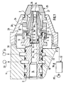
- the ribs between the grooves 9 a , 9 b comprise a rear part of enlarged diameter 10 received in the annular chamber 7, abutting against the radial shoulder 6 but not extending over the entire axial extension of the annular chamber 7.
- the central part 1 has a rear end 11 of reduced diameter while the peripheral part 2 has a rear end 12 of enlarged diameter, these rear ends being received in a stepped front housing 13 of the support 3 itself traversed by a central passage 14 through which the material filler, in the form of a homogeneous or compacted wire 15, coupled to drive means (not shown), advances in the central passage 8 of the central part 1 to exit, at the front end of the nozzle, by a central orifice 15 around which the conduits 9A, 9B open (FIG. 2).
- the passage 8 advantageously comprises, in the vicinity of the central orifice 16, a tubular liner 17 made of more wear-resistant material, for example stainless steel.
- the central nozzle part 1 and peripheral nozzle part 2 assembly is mounted and held against an internal shoulder of the housing 13 by a nut 24 screwed onto the front end of the support 3.
- a nut 24 screwed onto the front end of the support 3.
- an end sleeve 25 surrounding the peripheral part 2 and defining an internal housing ending, at the front, by a converging conical part 26 surrounding the front end of the peripheral part 2 by providing, around the latter, a passage annular 27.
- the sleeve 25 is held and locked in position in the nut 24 by a peripheral cover 28 screwed onto the front end of the body 4, thus forming an annular chamber 29 around the nut 24 and the rear part of the sleeve 25.
- the front end of the body 4 comprises an annular chamber 30 communicating, via an internal passage 31, with a source of carrier gas 32.
- the sleeve 24 comprises radial passages 33 establishing the communication between the chamber 29 in the cover 28 and the annular space between the sleeve 25 and the peripheral nozzle part 2.
- the carrier gas coming from the source 32 is distributed uniformly in the annular chamber 30, then passes into the annular chamber 29 by cooling the nut 24 and the rear part of the sleeve 25, then from there, through the passages 33, in the annular chamber between the sleeve 25 and the part peripheral 2 towards the outlet passage 26, by cooling the peripheral nozzle part 2.
- the nozzle design according to the invention allows obtaining a stepped heater, alternately mixing conduits 9 a, 9 b to differently distribute the combustion darts 34a , 34b around the material to be melted 15.
- the conduits 9b at a closer distance from the axis of the nozzle give a strong heating 34b of the material to be melted a short distance from the front face of the nozzle and cause a rapid rise in temperature. of the material 15.
- the other conduits 9a provide heating 34a further from the end of the nozzle and contribute to a gradual rise in temperature of the material to be melted 15.
- the design of the nozzle in two parts allows the execution of conduits of very different shapes, for example, as shown from left to right in Figure 2, grooves with rectangular, triangular or trapezoidal section.
- the ease of machining also makes it possible to increase the number of conduits and their angular distribution, and thus to improve the distribution of the heating on the material to be melted. It is thus also possible, as shown on the right in FIG. 2, to produce the conduits by a combination of drilled holes 9b and more or less deep grooves 9a, 9a ′.
Landscapes
- Chemical & Material Sciences (AREA)
- Engineering & Computer Science (AREA)
- Physics & Mathematics (AREA)
- Plasma & Fusion (AREA)
- Chemical Kinetics & Catalysis (AREA)
- Materials Engineering (AREA)
- Mechanical Engineering (AREA)
- Metallurgy (AREA)
- Organic Chemistry (AREA)
- Nozzles (AREA)
- Coating By Spraying Or Casting (AREA)
- Manufacture, Treatment Of Glass Fibers (AREA)
Applications Claiming Priority (2)
| Application Number | Priority Date | Filing Date | Title |
|---|---|---|---|
| FR9105081 | 1991-04-25 | ||
| FR9105081A FR2675819B1 (fr) | 1991-04-25 | 1991-04-25 | Procede et dispositif de formation de depot par projection d'un materiau d'apport sur substrat. |
Publications (2)
| Publication Number | Publication Date |
|---|---|
| EP0511076A1 true EP0511076A1 (de) | 1992-10-28 |
| EP0511076B1 EP0511076B1 (de) | 1994-12-07 |
Family
ID=9412223
Family Applications (1)
| Application Number | Title | Priority Date | Filing Date |
|---|---|---|---|
| EP92401113A Expired - Lifetime EP0511076B1 (de) | 1991-04-25 | 1992-04-21 | Anlage zum Spritzbeschichten von einem Zusatzwerkstoff auf einem Substrat |
Country Status (6)
| Country | Link |
|---|---|
| US (1) | US5269462A (de) |
| EP (1) | EP0511076B1 (de) |
| CA (1) | CA2066902A1 (de) |
| DE (1) | DE69200802T2 (de) |
| ES (1) | ES2066575T3 (de) |
| FR (1) | FR2675819B1 (de) |
Families Citing this family (3)
| Publication number | Priority date | Publication date | Assignee | Title |
|---|---|---|---|---|
| AR028415A1 (es) * | 2000-05-24 | 2003-05-07 | Fosbel Intellectual Ag | Procedimiento para formar una capa vetrea sobre una superficie refractaria |
| US20110209392A1 (en) * | 2010-02-26 | 2011-09-01 | Sharps Compliance, Inc. | Coated particulate and shaped fuels and methods for making and using same |
| US11919026B1 (en) * | 2018-05-31 | 2024-03-05 | Flame-Spray Industries, Inc. | System, apparatus, and method for deflected thermal spraying |
Citations (4)
| Publication number | Priority date | Publication date | Assignee | Title |
|---|---|---|---|---|
| EP0017944A1 (de) * | 1979-04-16 | 1980-10-29 | Union Carbide Corporation | Thermisches Spritzverfahren zur Herstellung von porösen Siedeflächen aus Aluminium |
| EP0323185A2 (de) * | 1987-12-28 | 1989-07-05 | Amoco Corporation | Apparat und Verfahren zum Erzeugen einer Beschichtung von hoher Dichte durch thermische Zerstäubung |
| EP0361710A1 (de) * | 1988-09-20 | 1990-04-04 | Plasma Technik Ag | Hochgeschwindigkeits-Flammspritzvorrichtung |
| EP0379119A1 (de) * | 1989-01-17 | 1990-07-25 | The Perkin-Elmer Corporation | Abgeschirmte Heissspritzpistole und Verwendung derselben |
Family Cites Families (5)
| Publication number | Priority date | Publication date | Assignee | Title |
|---|---|---|---|---|
| US2340903A (en) * | 1940-07-31 | 1944-02-08 | Metallizing Engineering Compan | Metal spray gun |
| CH250665A (de) * | 1944-04-20 | 1947-09-15 | Staeubli Willy | Metallspritzpistole. |
| US2832640A (en) * | 1954-12-09 | 1958-04-29 | Metallizing Engineering Co Inc | Heat fusible material spray gun |
| US3526366A (en) * | 1968-05-07 | 1970-09-01 | Bethlehem Steel Corp | Oxygen-jet cutting tip |
| US5186620A (en) * | 1991-04-01 | 1993-02-16 | Beckett Gas, Inc. | Gas burner nozzle |
-
1991
- 1991-04-25 FR FR9105081A patent/FR2675819B1/fr not_active Expired - Fee Related
-
1992
- 1992-04-21 DE DE69200802T patent/DE69200802T2/de not_active Expired - Fee Related
- 1992-04-21 EP EP92401113A patent/EP0511076B1/de not_active Expired - Lifetime
- 1992-04-21 ES ES92401113T patent/ES2066575T3/es not_active Expired - Lifetime
- 1992-04-22 US US07/872,012 patent/US5269462A/en not_active Expired - Fee Related
- 1992-04-23 CA CA002066902A patent/CA2066902A1/fr not_active Abandoned
Patent Citations (4)
| Publication number | Priority date | Publication date | Assignee | Title |
|---|---|---|---|---|
| EP0017944A1 (de) * | 1979-04-16 | 1980-10-29 | Union Carbide Corporation | Thermisches Spritzverfahren zur Herstellung von porösen Siedeflächen aus Aluminium |
| EP0323185A2 (de) * | 1987-12-28 | 1989-07-05 | Amoco Corporation | Apparat und Verfahren zum Erzeugen einer Beschichtung von hoher Dichte durch thermische Zerstäubung |
| EP0361710A1 (de) * | 1988-09-20 | 1990-04-04 | Plasma Technik Ag | Hochgeschwindigkeits-Flammspritzvorrichtung |
| EP0379119A1 (de) * | 1989-01-17 | 1990-07-25 | The Perkin-Elmer Corporation | Abgeschirmte Heissspritzpistole und Verwendung derselben |
Also Published As
| Publication number | Publication date |
|---|---|
| EP0511076B1 (de) | 1994-12-07 |
| CA2066902A1 (fr) | 1992-10-26 |
| DE69200802D1 (de) | 1995-01-19 |
| US5269462A (en) | 1993-12-14 |
| FR2675819A1 (fr) | 1992-10-30 |
| FR2675819B1 (fr) | 1994-04-08 |
| ES2066575T3 (es) | 1995-03-01 |
| DE69200802T2 (de) | 1995-04-13 |
Similar Documents
| Publication | Publication Date | Title |
|---|---|---|
| EP0574580B1 (de) | Koaxiale duese zur laser-oberflaechenbehandlung mit zufuhr von pulverfoermigem material | |
| EP0480828B1 (de) | Vorrichtung zur Zufuhr von Pulver zur Beschichtung mittels Laserstrahlbehandlung | |
| FR2648068A1 (fr) | Procede et appareil de soudage laser | |
| FR2636198A1 (fr) | Buse pour torche a plasma et procede pour introduire une poudre dans une torche a plasma | |
| FR2642672A1 (fr) | Appareil et procede de pulverisation sous plasma par un laser a flux axial | |
| CH694221A5 (fr) | Procédé de pulvérisation thermique, appareil de pulvérisation thermique et appareil de passage de poudre. | |
| FR2551377A1 (fr) | Procede de soudage a l'arc avec apport de metal sous gaz protecteur | |
| FR2662182A1 (fr) | Depot par projection de plasma a radiofrequence. | |
| FR2852541A1 (fr) | Procede de coupage plasma avec double flux de gaz | |
| FR2703557A1 (fr) | Torche plasma et procédé de mise en Óoeuvre pour le gougeage de pièces. | |
| FR2587920A1 (fr) | Procede et dispositif pour former une masse refractaire sur une surface | |
| EP0511076A1 (de) | Anlage zum Spritzbeschichten von einem Zusatzwerkstoff auf einem Substrat | |
| FR2658748A1 (fr) | Procede et dispositif de coupe par jet de liquide. | |
| CA2210513C (fr) | Couteau d'ecorcage et procede pour sa realisation | |
| WO2020136268A1 (fr) | Tête optique d'impression 3d par projection de poudre | |
| CA2522932C (fr) | Procede de revetement par flamme et dispositif correspondant | |
| FR2630752A1 (fr) | Procede de pulverisation a la flamme de materiaux en poudre et appareil de pulverisation a la flamme pour la mise en oeuvre de ce procede | |
| EP0634887B1 (de) | Plasmabrenner für übertragenen Lichtbogen | |
| CH643159A5 (fr) | Pistolet de projection a la flamme. | |
| FR2772887A1 (fr) | Bruleur a faible emission d'oxyde d'azote avec circuit de gaz recycle | |
| FR2681538A1 (fr) | Procede et dispositif de formation d'un depot par projection d'un materiau d'apport sur un substrat. | |
| FR2549579A1 (fr) | Bruleur a gaz pour pistolet de metallisation | |
| FR2692185A1 (fr) | Procédé de fabrication d'une pièce métallique par oxycoupage, dispositif d'oxycoupage et pièce métallique obtenue. | |
| EP0494024B1 (de) | Düse und Pistole zum thermischen Spritzen von Kunststoffmaterial | |
| CH654030A5 (fr) | Procede pour former un revetement resistant a l'usure sur la surface d'un substrat metallique. |
Legal Events
| Date | Code | Title | Description |
|---|---|---|---|
| PUAI | Public reference made under article 153(3) epc to a published international application that has entered the european phase |
Free format text: ORIGINAL CODE: 0009012 |
|
| 17P | Request for examination filed |
Effective date: 19920425 |
|
| AK | Designated contracting states |
Kind code of ref document: A1 Designated state(s): BE CH DE ES FR IT LI SE |
|
| 17Q | First examination report despatched |
Effective date: 19930623 |
|
| GRAA | (expected) grant |
Free format text: ORIGINAL CODE: 0009210 |
|
| AK | Designated contracting states |
Kind code of ref document: B1 Designated state(s): BE CH DE ES FR IT LI SE |
|
| ITF | It: translation for a ep patent filed | ||
| REF | Corresponds to: |
Ref document number: 69200802 Country of ref document: DE Date of ref document: 19950119 |
|
| REG | Reference to a national code |
Ref country code: ES Ref legal event code: FG2A Ref document number: 2066575 Country of ref document: ES Kind code of ref document: T3 |
|
| PG25 | Lapsed in a contracting state [announced via postgrant information from national office to epo] |
Ref country code: SE Effective date: 19950307 |
|
| PG25 | Lapsed in a contracting state [announced via postgrant information from national office to epo] |
Ref country code: LI Effective date: 19950430 Ref country code: CH Effective date: 19950430 Ref country code: BE Effective date: 19950430 |
|
| PLBE | No opposition filed within time limit |
Free format text: ORIGINAL CODE: 0009261 |
|
| STAA | Information on the status of an ep patent application or granted ep patent |
Free format text: STATUS: NO OPPOSITION FILED WITHIN TIME LIMIT |
|
| BERE | Be: lapsed |
Owner name: LA SOUDURE AUTOGENE FRANCAISE Effective date: 19950430 Owner name: S.A. L' AIR LIQUIDE POUR L'ETUDE ET L'EXPLOITATION Effective date: 19950430 |
|
| 26N | No opposition filed | ||
| REG | Reference to a national code |
Ref country code: CH Ref legal event code: PL |
|
| PGFP | Annual fee paid to national office [announced via postgrant information from national office to epo] |
Ref country code: FR Payment date: 19980312 Year of fee payment: 7 |
|
| PGFP | Annual fee paid to national office [announced via postgrant information from national office to epo] |
Ref country code: DE Payment date: 19980325 Year of fee payment: 7 |
|
| PGFP | Annual fee paid to national office [announced via postgrant information from national office to epo] |
Ref country code: ES Payment date: 19980415 Year of fee payment: 7 |
|
| PG25 | Lapsed in a contracting state [announced via postgrant information from national office to epo] |
Ref country code: ES Free format text: LAPSE BECAUSE OF EXPIRATION OF PROTECTION Effective date: 19990422 |
|
| PG25 | Lapsed in a contracting state [announced via postgrant information from national office to epo] |
Ref country code: FR Free format text: LAPSE BECAUSE OF NON-PAYMENT OF DUE FEES Effective date: 19991231 |
|
| REG | Reference to a national code |
Ref country code: FR Ref legal event code: ST |
|
| PG25 | Lapsed in a contracting state [announced via postgrant information from national office to epo] |
Ref country code: DE Free format text: LAPSE BECAUSE OF NON-PAYMENT OF DUE FEES Effective date: 20000201 |
|
| REG | Reference to a national code |
Ref country code: ES Ref legal event code: FD2A Effective date: 20010601 |
|
| PG25 | Lapsed in a contracting state [announced via postgrant information from national office to epo] |
Ref country code: IT Free format text: LAPSE BECAUSE OF NON-PAYMENT OF DUE FEES;WARNING: LAPSES OF ITALIAN PATENTS WITH EFFECTIVE DATE BEFORE 2007 MAY HAVE OCCURRED AT ANY TIME BEFORE 2007. THE CORRECT EFFECTIVE DATE MAY BE DIFFERENT FROM THE ONE RECORDED. Effective date: 20050421 |