EP0509800A2 - Druckmessungsgerät zur Untersuchung von therapeutischen Energiewellen - Google Patents
Druckmessungsgerät zur Untersuchung von therapeutischen Energiewellen Download PDFInfo
- Publication number
- EP0509800A2 EP0509800A2 EP92303408A EP92303408A EP0509800A2 EP 0509800 A2 EP0509800 A2 EP 0509800A2 EP 92303408 A EP92303408 A EP 92303408A EP 92303408 A EP92303408 A EP 92303408A EP 0509800 A2 EP0509800 A2 EP 0509800A2
- Authority
- EP
- European Patent Office
- Prior art keywords
- pressure
- sensing sheet
- pressure sensing
- marker
- mount
- Prior art date
- Legal status (The legal status is an assumption and is not a legal conclusion. Google has not performed a legal analysis and makes no representation as to the accuracy of the status listed.)
- Granted
Links
- 238000009530 blood pressure measurement Methods 0.000 title claims abstract description 29
- 230000001225 therapeutic effect Effects 0.000 title claims abstract description 10
- 239000003550 marker Substances 0.000 claims abstract description 66
- 230000035939 shock Effects 0.000 claims abstract description 56
- XLYOFNOQVPJJNP-UHFFFAOYSA-N water Substances O XLYOFNOQVPJJNP-UHFFFAOYSA-N 0.000 claims abstract description 19
- 238000013016 damping Methods 0.000 claims description 7
- 238000005259 measurement Methods 0.000 claims description 4
- 230000007423 decrease Effects 0.000 claims description 2
- 239000000463 material Substances 0.000 claims 2
- 238000004078 waterproofing Methods 0.000 claims 1
- 238000011282 treatment Methods 0.000 description 14
- 239000012528 membrane Substances 0.000 description 11
- 238000003384 imaging method Methods 0.000 description 6
- 238000000034 method Methods 0.000 description 3
- 238000002604 ultrasonography Methods 0.000 description 3
- 206010028980 Neoplasm Diseases 0.000 description 2
- 201000011510 cancer Diseases 0.000 description 2
- 238000010586 diagram Methods 0.000 description 2
- 230000000694 effects Effects 0.000 description 2
- 239000011521 glass Substances 0.000 description 2
- 239000005060 rubber Substances 0.000 description 2
- 239000004575 stone Substances 0.000 description 2
- 238000009210 therapy by ultrasound Methods 0.000 description 2
- 239000010936 titanium Substances 0.000 description 2
- 206010020843 Hyperthermia Diseases 0.000 description 1
- XEEYBQQBJWHFJM-UHFFFAOYSA-N Iron Chemical compound [Fe] XEEYBQQBJWHFJM-UHFFFAOYSA-N 0.000 description 1
- 208000000913 Kidney Calculi Diseases 0.000 description 1
- 206010029148 Nephrolithiasis Diseases 0.000 description 1
- RTAQQCXQSZGOHL-UHFFFAOYSA-N Titanium Chemical compound [Ti] RTAQQCXQSZGOHL-UHFFFAOYSA-N 0.000 description 1
- 235000010724 Wisteria floribunda Nutrition 0.000 description 1
- 239000000853 adhesive Substances 0.000 description 1
- 239000000919 ceramic Substances 0.000 description 1
- 230000008878 coupling Effects 0.000 description 1
- 238000010168 coupling process Methods 0.000 description 1
- 238000005859 coupling reaction Methods 0.000 description 1
- 201000010099 disease Diseases 0.000 description 1
- 208000037265 diseases, disorders, signs and symptoms Diseases 0.000 description 1
- 239000012530 fluid Substances 0.000 description 1
- 238000010438 heat treatment Methods 0.000 description 1
- 230000036031 hyperthermia Effects 0.000 description 1
- 238000007689 inspection Methods 0.000 description 1
- 230000004807 localization Effects 0.000 description 1
- 229920000728 polyester Polymers 0.000 description 1
- 238000004064 recycling Methods 0.000 description 1
- 230000000717 retained effect Effects 0.000 description 1
- 229910052710 silicon Inorganic materials 0.000 description 1
- 239000010703 silicon Substances 0.000 description 1
- 229910052715 tantalum Inorganic materials 0.000 description 1
- GUVRBAGPIYLISA-UHFFFAOYSA-N tantalum atom Chemical compound [Ta] GUVRBAGPIYLISA-UHFFFAOYSA-N 0.000 description 1
- 229910052719 titanium Inorganic materials 0.000 description 1
- 229910052721 tungsten Inorganic materials 0.000 description 1
- 239000010937 tungsten Substances 0.000 description 1
- WFKWXMTUELFFGS-UHFFFAOYSA-N tungsten Chemical compound [W] WFKWXMTUELFFGS-UHFFFAOYSA-N 0.000 description 1
Images







Classifications
-
- G—PHYSICS
- G01—MEASURING; TESTING
- G01H—MEASUREMENT OF MECHANICAL VIBRATIONS OR ULTRASONIC, SONIC OR INFRASONIC WAVES
- G01H3/00—Measuring characteristics of vibrations by using a detector in a fluid
- G01H3/10—Amplitude; Power
- G01H3/12—Amplitude; Power by electric means
- G01H3/125—Amplitude; Power by electric means for representing acoustic field distribution
-
- A—HUMAN NECESSITIES
- A61—MEDICAL OR VETERINARY SCIENCE; HYGIENE
- A61B—DIAGNOSIS; SURGERY; IDENTIFICATION
- A61B17/00—Surgical instruments, devices or methods
- A61B17/22—Implements for squeezing-off ulcers or the like on inner organs of the body; Implements for scraping-out cavities of body organs, e.g. bones; for invasive removal or destruction of calculus using mechanical vibrations; for removing obstructions in blood vessels, not otherwise provided for
- A61B17/22004—Implements for squeezing-off ulcers or the like on inner organs of the body; Implements for scraping-out cavities of body organs, e.g. bones; for invasive removal or destruction of calculus using mechanical vibrations; for removing obstructions in blood vessels, not otherwise provided for using mechanical vibrations, e.g. ultrasonic shock waves
- A61B17/22029—Means for measuring shock waves
-
- G—PHYSICS
- G01—MEASURING; TESTING
- G01H—MEASUREMENT OF MECHANICAL VIBRATIONS OR ULTRASONIC, SONIC OR INFRASONIC WAVES
- G01H3/00—Measuring characteristics of vibrations by using a detector in a fluid
- G01H3/005—Testing or calibrating of detectors covered by the subgroups of G01H3/00
-
- A—HUMAN NECESSITIES
- A61—MEDICAL OR VETERINARY SCIENCE; HYGIENE
- A61B—DIAGNOSIS; SURGERY; IDENTIFICATION
- A61B17/00—Surgical instruments, devices or methods
- A61B2017/00681—Aspects not otherwise provided for
- A61B2017/00707—Dummies, phantoms; Devices simulating patient or parts of patient
- A61B2017/00712—Dummies, phantoms; Devices simulating patient or parts of patient simulating mathematical properties, e.g. for testing of positioning in the isocentre or focus
Definitions
- This invention relates to a pressure measurement apparatus for inspecting therapeutic energy waves,especially for inspecting the pressure profile at the focal area and the deviation of the focal point from an actual focal position in a treatment apparatus for using shock wave or ultrasound.
- shock wave treatment apparatus e.g. lithotripter for disintegrating calculi in a body.
- an ultrasonic treatment apparatus has been used for heating and treating a cancer in a body.
- shock waves or ultrasonic waves which are released from an applicator which consists of concave shaped piezo-ceramics and a water bag containing coupling fluid,are focused to a focal point in a patients body.
- the applicator is set so that the focal point of the energy is coincident with a target e. g. stone or cancer.
- a target e. g. stone or cancer.
- a pressure transducer e.g. membrane type or a needle type hydrophone is used.Both the membrane type and the needle type hydrophone are discussed in detail in " SHOCK WAVE SENSORS: I.REQUIREMENTS AND DESIGN,Journal of Lithotripsy and Stone Disease Vol.3,No.1,1991" .
- a pressure profile was decided by exposing only once.But it was difficult to detect the pressure sensing point of the membrane type hydrophone using ultrasound or X-ray imaging apparatus because a pressure sensing point of that hydrophone can't be unvisible by those imaging apparatus.In short,it is difficult for the user to know the deviation between the actual focal position of the applicator and the imaging focal position.
- the needle typehydrophone e.g. IMOTEC Corp.-made piezo-electric type mini pressure pickup:Type80-0.5-40
- the needle type-hydrophone is broken easily,so that the number of shock wave measurement is restricted.As a result,the needle type-hydrophone could't detect the pressure profile of the focal area because it needs many measurement points. Therefore,it is difficult to detect the deviation between the actual focal position of the applicator and the imaging focal position using the needle typehydrophone.
- the pressure measurement apparatus for inspecting shock wave has both merits and demerits. If the actual focal position of the applicatior coincides with the focal position on the image display for target localization,the pressure of focal position is measured exactly using a hydrophone.But if the actual focal position of the applicator deviates from the focal position on the image display,the pressure measurement of the direction and the distance of the deviation between the actual focal position of the applicator and the focal position on the image display is very complicated. Thus it is difficult for the user to judge the focal position.
- the pressure measurement apparatus for inspecting therapeutic energy waves comprises a pressure sensing sheet which changes visually or electrically according to the pressure of the energy waves and a marker for being set to the focal position on display imaging, which is mounted on the pressure sensing sheet.
- the pressure measurment apparatus for inspecting therapeutic energy waves further comprises a mount for holding the pressure sensing sheet as flat shape, a mount holder for holding the mount, a marker for being set to the focal position held above the pressure sensing sheet, and a holder means for holding the mount holder in a water tank.
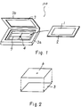
- the pressure measurment apparatus in Fig.1 comprises a pressure sensing sheet 1, a mount for pressure sensing sheet 2, a mount holder 3 and a marker 4.
- the pressure sensing sheet 1 consists of a pressure sensing paper 5 whose color is changed partially by additional pressure thereon,and a transparent sticky tape for water-proof.
- the pressure sensing paper 5 is e.g. FUJI FILM Corp.-made prescales and 0.045 by 0.04m.
- the mount for pressure sensing sheet 2 has a similar structure to a mount for slides which is marketed.
- the mount for pressure sensing sheet 2 retains the pressure sensing sheet 1 in a flat shape.
- the pressure sensing sheet 1 is exchanged for recycling.Further the mount for pressure sensing sheet 2 may be a disposable type which retains the pressure sensing sheet 1.
- the mount holder 3 holds the mount for pressure sensing sheet 2.
- the mount holder 3 consist of box portion 3a which is a flat shape and a cap portion 3b.
- the box portion 3a has a step for retaining the mount for pressure sensing sheet 2.
- the mount for pressure sensing sheet 2 is clipped by the box portion 3a and the cap portion 3b.
- the marker 4 is used to set a position of ultrasonic and/or X-rays.
- the marker 4 is a small radio-opaque,which is e.g.
- the marker 4 is retained at the center of the open side of the mount holder 3 by wire 7,which has nearly the acoustic impedance of water and is radio-lucent,e.g. rubber,glass,silicon(Si) and polyester.In this case,the marker 4 is held above the pressure sensing sheet 1. If the marker 4 contacts the pressure sensing sheet 1,when the shock wave exposes the pressure sensing sheet 1,a reflection could cause contact between the pressure sensing sheet 1 and the marker 4.As a result,it is impossible to exact by measure the focal pressure.
- the pressure measurement apparatus When the pressure of a shock wave is measured by using the pressure measurement apparatus, the pressure measurement apparatus is held in a water tank by a holder. The pressure measurement apparatus is exposed to the shock wave by the shock wave source 23,which is on applicator of a water bag type.
- Fig.3 shows the pressure measuringment apparatus of the present invention which is established in the shock wave treatment apparatus.As shown in the Fig.3,the pressure sensing sheet 1,the mount 2 and the mount holder 3 are mounted in the water tank 20 by holder 21.When the pressure measurement apparatus measures the focal position of the shock wave source 23,the pressure measurment apparatus must be in a set position.
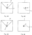
- Fig.4 relates the focal position marker 50 on the image display 60,which is used to set the focal position of the lithotripter and color emitting state.
- Fig.4A and 4B show that the actual focal position of shock wave(i.e. spot 80) coincides with the focal position marker 50 on image display 60.
- Fig.4B shows the relative position of the focal position of the shock wave in the pressure sensing sheet 1 and marker 4.Further,the position is set by using X-rays,because the marker 4 is radio-opaque.
- the position is set as the marker 4 coincides with the focal position marker 50.But actually,the spot 80 deviates from the marker 4.After the position is set according to distance and direction between the marker 4 and the spot 80 on the pressure sensing sheet 1,the shock wave source 23 is operated.In this way, the user sets the focal position by referring to the deviation of the spot 80 on the pressure sensing sheet 1. Finally, as shown in Fig.4C and 4D, the spot 80 coincides with the focal position marker 50 and the marker 4.
- Fig.4 shows the set position of the marker 4 which is coincident with the focal position marker 50 on the image display 60.
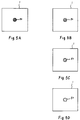
- this invention operates to adjust the focus pressure to the most suitable pressure. Concretely speaking,when the maximum pressure of the focal position,which is guaranted by the shock wave treatment apparatus,comes down 0%,,10%,20% and 30% respectively,each color emitting state is recorded as a standerd color emitting state.
- Fig.5A and 6A show the color emitting state of the pressure sensing sheet 1,when the maximum pressure of the focal position comes down.
- Fig.5B shows the color emitting state when the pressure value comes down 10% from the maximum pressure.
- Fig.5C shows the color emitting state when the pressure value comes down 20% from the maximum.
- Fig.5D shows the color emitting state when the pressure value comes down 30% from the maximum.
- Fig.6 is different from the Fig.5,in that Fig.5 shows, when the maximum pressure comes down, the color is more light,but in Fig.6,when the maximum pressure comes down,the color area is smaller.Thus,the user compares the actual color emitting area with a standard color emitting which was previously recorded as the maximum pressure,when the shock wave treatment apparatus is inspected by the user.The user can judge how much the pressure has come down.As a result,the user can decide whether the actual maximum pressure is enough,and whether a serviceman must examine the shock wave treatment apparatus.
- Fig.7 shows another embodiment of the pressure measure apparatus according to the present invention,which is different from the mount holder 3 of the Fig.1.
- the mount holder 3 consists of a frame,which has an opening side and has gutter 8 to insert the mount of the pressure sensing sheet 2 from the opening side,as shown pointing arrow in Fig.7.
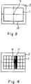
- Fig.8 and 9 show other embodiments of the pressure sensing sheet 1 and the mount for pressure sensing sheet 2.
- an indication mark for focal position 9 has a diferent color(e.g. blue,if the color of the pressure sensing paper 5 is red) from the color of the pressure sensing paper 5.
- the indication marker 9 is marked on the surface of transparent tape 6,which contacts the pressure sensing sheet 1 as shown Fig.2,and the marker 4.
- the indication mark for focal position 9 is e.g. a dot,a cross or two stright lines,and the cross point indicates focal position.
- the mount for pressure sensing sheet 2 has scale 10,which has a zero point corresponding to the focal position for focal position 9.As a result,deviation of actual focal position and geometric focal position may be measured by user quantitatively.
- cross hair 11 is printed on the pressure sensing sheet 1.
- the zero point of the cross hair 11 is the focal position of the indication mark 9.
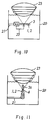
- Figs.10-14 show the embodiment in which the pressure measurement apparatus of the present invention is actually to applied the shock wave treatment apparatus.
- the pressure measurement apparatus is established horizontally and the pressure sensing sheet is established perpendicular to the focus direction of the shock wave by holder 21 in the water tank 20.
- the point of the shock wave source 23 is dipped in the water bag and the pressure measurment apparatus measures the focal position pressure for the shock wave irradiated from the shock wave source 23.
- Fig.11 shows another embodiment different from Fig.10.
- the pressure measurement apparatus is established vertically ,in other word parallel to the focus direction of the shock wave.
- the mount for pressure sensing sheet 2 whose one side is removed as shown in Fig.9,is adopted and the mount holder 3,whose one side is removed.As shown in Fig.7,is adopted,the pressure sensing sheet 1 is set parallel to the focus direction of shock wave and the pressure measurement apparatus can measure the pressure distribution in the focus direction of the shock wave.
- Fig.12 shows another embodiment wherein shock wave source 23 contacts a membrane 24,which is established on the base of the water tank 20.
- Fig.13 shows another embodiment wherein shock wave source 23 contacts a membrane 24,which is established on the side of the water tank 20.
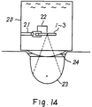
- Fig.14 shows another embodiment applied to an open type lithotripter.This case which is similar to Fig.12,shows shock wave source 23 contacting a membrane 24,which is established on the base of the water tank 20.
- Fig.11 and Fig.13 show the small ball as the marker 4.But in the embodiments shown in Fig.10, 12 and 14,in which the pressure measurement apparatus is established horizontally,it is possible to hold needle type marker 22 to the water tank 20 or holder 21 without contacting the pressure sensing sheet 1.
- the marker 4(22) was established at the back of the pressure sensing sheet 1,which is opposite to the side of the shock wave source.But as for the lithotripter which is an ultrasonic portrait type,the ultrasonic is reflected in front of the pressure sensing sheet 1. Thus,it often happens that the marker 4 at the back of the pressure sensing sheet 1 is not visible.In this case,to confirm position setting accuracy,the marker 4 is established in front of the pressure sensing sheet 1. In this method,the marker 4 is held on the surface of the pressure sensing sheet 1 by adhesive agent,as shown in Fig.15.
- Fig.16 shows the embodiment of the pressure measurment apparatus,which is applied to this method.
- the pressure measurment apparatus prepares the marker 4,which is mounted on top of thin arm 12 and the arm 12 is mounted on driving mechanism 13,which can rotate. If the arm 12 is rotated by the driving mechanism 13,marker 4 is set in front of the pressure sensing sheet 1 and is detached from front of the pressure sensing sheet 1.
- Fig.17 shows another embodiment in that the marker 4,which is a needle type,contacts the back of the pressure sensing sheet 1.
- FIG.17A shows a diagram on the top view of the pressure measurement apparatus in this embodiment.
- Fig.17B shows a diagram on the side view of the pressure measurement apparatus in this embodiment.
- the pressure measurement apparatus is established in a water bag and the focal position of the shock wave source is set so that the focal position coincides with the focal position marker(NOT shown) in the ultrasonic portrait.In this state,if the shock wave is exposed, a color emitting point corresponding to the pressure of the shock wave appears on the pressure sensing sheet 1.
- an object an innerprove
- the pressure sensing sheet 1 which contacts the marker 4.As a result, a point,where is held between the innerprove and the marker 4,appears as strong color emitting point.Thus,if the interval between two color emitting points on the pressure sensing sheet 1 is measured,the deviation between the focal point of the shock wave source and the marker 4 is detected exactly.Futher the deviation is detected by holding up the pressure sensing sheet 1 to light.It is also detected by lighting from the opposite surface of the pressure sensing sheet 1.
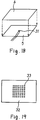
- FIGs.18 and 19 show the other embodiment of the pressure sensing sheet.
- the pressure transducer 31 which is a small membrane type,is held by the transparent sticky tape for water-proof 6 on the pressure sensing paper 5.
- the pressure measurement apparatus can measure the focal position pressure exactly.
- Fig.19 shows a pressure sensing sheet which is a hydrophone consisting of electrodes 33 arranged by the same interval on a membrane type piezo-electric film 32.
- an electric signal which has a different level corresponding to the pressure distribution of the shock wave,is gained from the electrode as the output of the hydrophone.
- the sound field,or peak pressure in the focal position still more deviation between the focal position corresponding to the relative position of the applicator and the actual focal position,are measured.As for the value of these measurement which result,the user can understand whether the output will break the calculus can judge if the treatment apparatus is operating properly and can detect any unusual output easily.
- the pressure sensing sheet has pressure a sensible extent of e.g. 50-100Mpa.But it often happens that the shock wave irradiated by lithotoripter is not within the pressure sensible extent.
- Fig.20 shows pressure sensing sheet for high-pressure.
- a damping film 15 e.g. a rubber sheet,is adhered.
- the space between the damping film 15 and the pressure sensing sheet 1 is a vacuum. If the pressure sensing sheet is used in the same manner the earlier described embodiment,the transparency output of shock wave decreases by 20%,so the pressure sensing sheet can detect the maximum output of 120Mpa of lithotripter.Further,by choosing the acoustic characteristics,a suitable damping quantity is set up for the damping film 15.
- Fig.21 shows a pressure sensing sheet for low-pressure.
- a reflection film 16 which has an acoustic impedance more than that of the sensing sheet 1,e.g. stainless,is adhered.
- the space between the reflection film 16 and the pressure sensing sheet 1 is a vacuum. If the pressure sensing sheet is used in the described embodiments,the output of the shock wave may be increase by 50%,so the pressure sensing sheet may be used for the maximum output 40Mpma of lithotoripter.
- pressure sensing paper 5 may be exchanged for heat sensing paper.
- a heat sensing sheet when the heat sensing paper is adopted,can apply for inspection of ultrasonic treatment apparatus for hyperthermia.
Landscapes
- Health & Medical Sciences (AREA)
- Physics & Mathematics (AREA)
- Engineering & Computer Science (AREA)
- Surgery (AREA)
- General Physics & Mathematics (AREA)
- Life Sciences & Earth Sciences (AREA)
- Animal Behavior & Ethology (AREA)
- Veterinary Medicine (AREA)
- Biomedical Technology (AREA)
- Heart & Thoracic Surgery (AREA)
- Medical Informatics (AREA)
- Molecular Biology (AREA)
- Vascular Medicine (AREA)
- General Health & Medical Sciences (AREA)
- Public Health (AREA)
- Nuclear Medicine, Radiotherapy & Molecular Imaging (AREA)
- Orthopedic Medicine & Surgery (AREA)
- Mechanical Engineering (AREA)
- Acoustics & Sound (AREA)
- Radar, Positioning & Navigation (AREA)
- Remote Sensing (AREA)
- Surgical Instruments (AREA)
- Measurement Of Mechanical Vibrations Or Ultrasonic Waves (AREA)
- Measuring Fluid Pressure (AREA)
Applications Claiming Priority (4)
| Application Number | Priority Date | Filing Date | Title |
|---|---|---|---|
| JP111045/91 | 1991-04-15 | ||
| JP11104591 | 1991-04-15 | ||
| JP4055961A JPH0572071A (ja) | 1991-04-15 | 1992-03-16 | 圧力測定装置 |
| JP55961/92 | 1992-03-16 |
Publications (3)
| Publication Number | Publication Date |
|---|---|
| EP0509800A2 true EP0509800A2 (de) | 1992-10-21 |
| EP0509800A3 EP0509800A3 (en) | 1993-07-21 |
| EP0509800B1 EP0509800B1 (de) | 1997-06-18 |
Family
ID=26396861
Family Applications (1)
| Application Number | Title | Priority Date | Filing Date |
|---|---|---|---|
| EP92303408A Expired - Lifetime EP0509800B1 (de) | 1991-04-15 | 1992-04-15 | Druckmessungsgerät zur Untersuchung von therapeutischen Energiewellen |
Country Status (4)
| Country | Link |
|---|---|
| US (2) | US5357805A (de) |
| EP (1) | EP0509800B1 (de) |
| JP (1) | JPH0572071A (de) |
| DE (1) | DE69220414T2 (de) |
Cited By (1)
| Publication number | Priority date | Publication date | Assignee | Title |
|---|---|---|---|---|
| CN115389002A (zh) * | 2022-08-24 | 2022-11-25 | 深圳市慧康医疗器械有限公司 | 一种体外冲击波碎石机的压力脉冲测量装置以及方法 |
Families Citing this family (8)
| Publication number | Priority date | Publication date | Assignee | Title |
|---|---|---|---|---|
| DE4310924C2 (de) * | 1993-04-02 | 1995-01-26 | Siemens Ag | Therapieeinrichtung zur Behandlung von pathologischem Gewebe mit Ultraschallwellen und einem Katheder |
| US6695834B2 (en) | 2002-01-25 | 2004-02-24 | Scimed Life Systems, Inc. | Apparatus and method for stone removal from a body |
| DE102004038848B4 (de) * | 2004-08-10 | 2009-10-08 | Siemens Ag | Stoßwellenkopf mit einer Einrichtung zur Kontrolle der Lage seines Fokus |
| US20100068266A1 (en) | 2008-09-16 | 2010-03-18 | Searete Llc, A Limited Liability Corporation Of The State Of Delaware | Ex vivo-modifiable multiple-release state final dosage form |
| US20100068153A1 (en) * | 2008-09-16 | 2010-03-18 | Searete Llc, A Limited Liability Corporation Of The State Of Delaware | Ex vivo activatable final dosage form |
| US20100069887A1 (en) * | 2008-09-16 | 2010-03-18 | Searete Llc, A Limited Liability Corporation Of The State Of Delaware | Multiple chamber ex vivo adjustable-release final dosage form |
| US8806942B2 (en) | 2008-12-05 | 2014-08-19 | National University Corporation Saitama University | Evaluation method for botanical-integrity of vascular plant, irrigating method to vascular plant, film electret sensor and film ECM array |
| GB2555464B (en) | 2016-10-31 | 2022-04-06 | Elekta Ab | Radiotherapy dose distribution measurement |
Family Cites Families (13)
| Publication number | Priority date | Publication date | Assignee | Title |
|---|---|---|---|---|
| DE842548C (de) * | 1949-05-04 | 1952-06-30 | Hans Heinrich Dr Rust | Verfahren zur Herstellung schalloptischer Abbildungen |
| DE929327C (de) * | 1951-12-05 | 1955-06-23 | Schoeller & Co Elektrotech | Verfahren zur Herstellung akustisch-optischer Bildwandler |
| US3832669A (en) * | 1970-08-10 | 1974-08-27 | Royal Medical Corp | Temperature-sensing device |
| US3878712A (en) * | 1973-11-05 | 1975-04-22 | Ned Chapin | Pressure recordation |
| US4331030A (en) * | 1978-12-21 | 1982-05-25 | Webster David F | Tire inspection and recording device |
| GB8411480D0 (en) * | 1984-05-04 | 1984-06-13 | Raychem Corp | Sensor array |
| US4722609A (en) * | 1985-05-28 | 1988-02-02 | The United States Of America As Represented By The Secretary Of The Navy | High frequency response multilayer heat flux gauge configuration |
| US4812050A (en) * | 1985-05-28 | 1989-03-14 | The United States Of America As Represented By The Secretary Of The Navy | Method for calibrating a heat flux gauge |
| US4599198A (en) * | 1985-08-02 | 1986-07-08 | Pfizer Inc. | Intermediates in polypeptide synthesis |
| GB8520182D0 (en) * | 1985-08-12 | 1985-09-18 | St Thomas Hospital Special Tru | Calibration system |
| US4813415A (en) * | 1986-08-18 | 1989-03-21 | Siemens Aktiengesellschaft | Sensor for evaluation of shock wave pulses |
| DE8622104U1 (de) * | 1986-08-18 | 1987-12-17 | Siemens AG, 1000 Berlin und 8000 München | Vorrichtung zum Zertrümmern von Konkrementen |
| US4774835A (en) * | 1986-11-13 | 1988-10-04 | The United States Of America As Represented By The Administrator Of The National Aeronautics And Space Administration | Method for laminar boundary layer transition visualization in flight |
-
1992
- 1992-03-16 JP JP4055961A patent/JPH0572071A/ja active Pending
- 1992-04-15 US US07/868,657 patent/US5357805A/en not_active Expired - Lifetime
- 1992-04-15 EP EP92303408A patent/EP0509800B1/de not_active Expired - Lifetime
- 1992-04-15 DE DE69220414T patent/DE69220414T2/de not_active Expired - Fee Related
-
1994
- 1994-07-26 US US08/280,546 patent/US5465625A/en not_active Expired - Lifetime
Cited By (1)
| Publication number | Priority date | Publication date | Assignee | Title |
|---|---|---|---|---|
| CN115389002A (zh) * | 2022-08-24 | 2022-11-25 | 深圳市慧康医疗器械有限公司 | 一种体外冲击波碎石机的压力脉冲测量装置以及方法 |
Also Published As
| Publication number | Publication date |
|---|---|
| US5465625A (en) | 1995-11-14 |
| EP0509800A3 (en) | 1993-07-21 |
| JPH0572071A (ja) | 1993-03-23 |
| US5357805A (en) | 1994-10-25 |
| EP0509800B1 (de) | 1997-06-18 |
| DE69220414T2 (de) | 1997-10-30 |
| DE69220414D1 (de) | 1997-07-24 |
Similar Documents
| Publication | Publication Date | Title |
|---|---|---|
| US5072733A (en) | Shock wave lithotripter and method for using the same | |
| EP0553257B1 (de) | Katheter mit kreisringförmigem ultraschall-wandler | |
| US4457311A (en) | Ultrasound imaging system for scanning the human back | |
| US4355643A (en) | Vacuum cup doppler flow transducer and method for using same | |
| US4932414A (en) | System of therapeutic ultrasound and real-time ultrasonic scanning | |
| US4476873A (en) | Ultrasound scanning system for skeletal imaging | |
| EP0219988B1 (de) | Unabhängiges, tragbares Ultraschall-Instrument zur Anwendung in der Augenheilkunde | |
| Bronson | Development of a simple B-scan ultrasonoscope | |
| EP1915946B1 (de) | Mammografiegerät | |
| EP0509800B1 (de) | Druckmessungsgerät zur Untersuchung von therapeutischen Energiewellen | |
| US4437468A (en) | Ultrasound scanning system with semi-independent transducer array | |
| US6679267B2 (en) | Sterile drape for use with laser tracking system | |
| WO1993022976A1 (en) | Method and apparatus to establish target coordinates for lithotripsy | |
| JPH06504686A (ja) | 超音波画像システム及び同用音波部材 | |
| US20190388062A1 (en) | Apparatus, System, and Method for Increasing Object Visibility | |
| KR101838590B1 (ko) | 충격파 생성기의 성능 검사 장치 | |
| JPH0852151A (ja) | 結石砕石装置及び結石位置確定装置 | |
| JP3614288B2 (ja) | 治療器具用焦点追跡装置 | |
| IL103438A (en) | In vitro healing device | |
| JPH1033547A (ja) | 治療装置 | |
| EP0211680A1 (de) | Verfahren zur Eichung eines Nierensteinzertrümmerers | |
| US4813415A (en) | Sensor for evaluation of shock wave pulses | |
| US20030174809A1 (en) | Method and apparatus for the three-dimensional location of a concrement | |
| JPH09103430A (ja) | 超音波骨分析装置及び身体の部分を検知する方法 | |
| ERKONEN et al. | Ocular foreign body localization |
Legal Events
| Date | Code | Title | Description |
|---|---|---|---|
| PUAI | Public reference made under article 153(3) epc to a published international application that has entered the european phase |
Free format text: ORIGINAL CODE: 0009012 |
|
| 17P | Request for examination filed |
Effective date: 19920508 |
|
| AK | Designated contracting states |
Kind code of ref document: A2 Designated state(s): DE FR |
|
| PUAL | Search report despatched |
Free format text: ORIGINAL CODE: 0009013 |
|
| AK | Designated contracting states |
Kind code of ref document: A3 Designated state(s): DE FR |
|
| 17Q | First examination report despatched |
Effective date: 19950116 |
|
| GRAG | Despatch of communication of intention to grant |
Free format text: ORIGINAL CODE: EPIDOS AGRA |
|
| GRAH | Despatch of communication of intention to grant a patent |
Free format text: ORIGINAL CODE: EPIDOS IGRA |
|
| GRAH | Despatch of communication of intention to grant a patent |
Free format text: ORIGINAL CODE: EPIDOS IGRA |
|
| GRAA | (expected) grant |
Free format text: ORIGINAL CODE: 0009210 |
|
| AK | Designated contracting states |
Kind code of ref document: B1 Designated state(s): DE FR |
|
| REF | Corresponds to: |
Ref document number: 69220414 Country of ref document: DE Date of ref document: 19970724 |
|
| ET | Fr: translation filed | ||
| PLBE | No opposition filed within time limit |
Free format text: ORIGINAL CODE: 0009261 |
|
| STAA | Information on the status of an ep patent application or granted ep patent |
Free format text: STATUS: NO OPPOSITION FILED WITHIN TIME LIMIT |
|
| 26N | No opposition filed | ||
| PGFP | Annual fee paid to national office [announced via postgrant information from national office to epo] |
Ref country code: FR Payment date: 19990409 Year of fee payment: 8 |
|
| PGFP | Annual fee paid to national office [announced via postgrant information from national office to epo] |
Ref country code: DE Payment date: 19990426 Year of fee payment: 8 |
|
| PG25 | Lapsed in a contracting state [announced via postgrant information from national office to epo] |
Ref country code: FR Free format text: LAPSE BECAUSE OF NON-PAYMENT OF DUE FEES Effective date: 20001229 |
|
| PG25 | Lapsed in a contracting state [announced via postgrant information from national office to epo] |
Ref country code: DE Free format text: LAPSE BECAUSE OF NON-PAYMENT OF DUE FEES Effective date: 20010201 |
|
| REG | Reference to a national code |
Ref country code: FR Ref legal event code: ST |