EP0509773B1 - Device for external chest compression - Google Patents
Device for external chest compression Download PDFInfo
- Publication number
- EP0509773B1 EP0509773B1 EP92303367A EP92303367A EP0509773B1 EP 0509773 B1 EP0509773 B1 EP 0509773B1 EP 92303367 A EP92303367 A EP 92303367A EP 92303367 A EP92303367 A EP 92303367A EP 0509773 B1 EP0509773 B1 EP 0509773B1
- Authority
- EP
- European Patent Office
- Prior art keywords
- patient
- applicator
- chest
- lip
- applicator body
- Prior art date
- Legal status (The legal status is an assumption and is not a legal conclusion. Google has not performed a legal analysis and makes no representation as to the accuracy of the status listed.)
- Expired - Lifetime
Links
- 238000007906 compression Methods 0.000 title claims description 32
- 230000006835 compression Effects 0.000 title claims description 32
- 210000000038 chest Anatomy 0.000 claims description 57
- 238000002680 cardiopulmonary resuscitation Methods 0.000 claims description 37
- 238000009423 ventilation Methods 0.000 claims description 13
- 210000001562 sternum Anatomy 0.000 claims description 9
- 239000000853 adhesive Substances 0.000 claims description 8
- 230000001070 adhesive effect Effects 0.000 claims description 8
- 238000003825 pressing Methods 0.000 claims description 3
- 230000036772 blood pressure Effects 0.000 claims description 2
- 230000036387 respiratory rate Effects 0.000 claims description 2
- 210000000115 thoracic cavity Anatomy 0.000 claims description 2
- 230000005540 biological transmission Effects 0.000 claims 1
- 238000000034 method Methods 0.000 description 18
- 208000014674 injury Diseases 0.000 description 8
- 210000004072 lung Anatomy 0.000 description 7
- 208000027418 Wounds and injury Diseases 0.000 description 6
- 230000008901 benefit Effects 0.000 description 6
- 230000006378 damage Effects 0.000 description 6
- 238000012544 monitoring process Methods 0.000 description 6
- 210000004369 blood Anatomy 0.000 description 5
- 239000008280 blood Substances 0.000 description 5
- 230000017531 blood circulation Effects 0.000 description 5
- 230000004087 circulation Effects 0.000 description 5
- 239000010410 layer Substances 0.000 description 5
- 239000000463 material Substances 0.000 description 5
- 230000029058 respiratory gaseous exchange Effects 0.000 description 5
- 230000000747 cardiac effect Effects 0.000 description 4
- 230000035939 shock Effects 0.000 description 4
- 238000009826 distribution Methods 0.000 description 3
- 206010049418 Sudden Cardiac Death Diseases 0.000 description 2
- 230000001464 adherent effect Effects 0.000 description 2
- QVGXLLKOCUKJST-UHFFFAOYSA-N atomic oxygen Chemical compound [O] QVGXLLKOCUKJST-UHFFFAOYSA-N 0.000 description 2
- 229920003052 natural elastomer Polymers 0.000 description 2
- 229920001194 natural rubber Polymers 0.000 description 2
- 239000001301 oxygen Substances 0.000 description 2
- 229910052760 oxygen Inorganic materials 0.000 description 2
- 230000002093 peripheral effect Effects 0.000 description 2
- -1 poly(vinyl pyrrolidone) Polymers 0.000 description 2
- 239000007787 solid Substances 0.000 description 2
- 208000014221 sudden cardiac arrest Diseases 0.000 description 2
- 229920003051 synthetic elastomer Polymers 0.000 description 2
- 239000005061 synthetic rubber Substances 0.000 description 2
- 210000000779 thoracic wall Anatomy 0.000 description 2
- 206010003497 Asphyxia Diseases 0.000 description 1
- 208000010496 Heart Arrest Diseases 0.000 description 1
- 244000043261 Hevea brasiliensis Species 0.000 description 1
- 229920002367 Polyisobutene Polymers 0.000 description 1
- 239000004820 Pressure-sensitive adhesive Substances 0.000 description 1
- 206010061363 Skeletal injury Diseases 0.000 description 1
- 206010056287 Sternal injury Diseases 0.000 description 1
- 210000001015 abdomen Anatomy 0.000 description 1
- 239000006096 absorbing agent Substances 0.000 description 1
- NIXOWILDQLNWCW-UHFFFAOYSA-N acrylic acid group Chemical group C(C=C)(=O)O NIXOWILDQLNWCW-UHFFFAOYSA-N 0.000 description 1
- 239000012790 adhesive layer Substances 0.000 description 1
- 208000008784 apnea Diseases 0.000 description 1
- 210000001367 artery Anatomy 0.000 description 1
- 230000004888 barrier function Effects 0.000 description 1
- 210000004556 brain Anatomy 0.000 description 1
- 230000006931 brain damage Effects 0.000 description 1
- 210000005242 cardiac chamber Anatomy 0.000 description 1
- 230000003683 cardiac damage Effects 0.000 description 1
- 238000010276 construction Methods 0.000 description 1
- 230000000694 effects Effects 0.000 description 1
- 239000013013 elastic material Substances 0.000 description 1
- 238000009472 formulation Methods 0.000 description 1
- 239000007789 gas Substances 0.000 description 1
- 239000000499 gel Substances 0.000 description 1
- 208000019622 heart disease Diseases 0.000 description 1
- 239000000017 hydrogel Substances 0.000 description 1
- 230000006872 improvement Effects 0.000 description 1
- 230000007246 mechanism Effects 0.000 description 1
- 239000000203 mixture Substances 0.000 description 1
- 238000012806 monitoring device Methods 0.000 description 1
- 238000000465 moulding Methods 0.000 description 1
- 238000006213 oxygenation reaction Methods 0.000 description 1
- 238000009527 percussion Methods 0.000 description 1
- 230000000737 periodic effect Effects 0.000 description 1
- 210000005259 peripheral blood Anatomy 0.000 description 1
- 239000011886 peripheral blood Substances 0.000 description 1
- 238000000554 physical therapy Methods 0.000 description 1
- 230000008569 process Effects 0.000 description 1
- 230000001681 protective effect Effects 0.000 description 1
- 239000012858 resilient material Substances 0.000 description 1
- 238000007789 sealing Methods 0.000 description 1
- 230000000153 supplemental effect Effects 0.000 description 1
- 230000004083 survival effect Effects 0.000 description 1
- 238000002560 therapeutic procedure Methods 0.000 description 1
- 230000008733 trauma Effects 0.000 description 1
- 230000000472 traumatic effect Effects 0.000 description 1
- 230000008736 traumatic injury Effects 0.000 description 1
- 238000009827 uniform distribution Methods 0.000 description 1
Images


Classifications
-
- A—HUMAN NECESSITIES
- A61—MEDICAL OR VETERINARY SCIENCE; HYGIENE
- A61H—PHYSICAL THERAPY APPARATUS, e.g. DEVICES FOR LOCATING OR STIMULATING REFLEX POINTS IN THE BODY; ARTIFICIAL RESPIRATION; MASSAGE; BATHING DEVICES FOR SPECIAL THERAPEUTIC OR HYGIENIC PURPOSES OR SPECIFIC PARTS OF THE BODY
- A61H31/00—Artificial respiration by a force applied to the chest; Heart stimulation, e.g. heart massage
-
- A—HUMAN NECESSITIES
- A61—MEDICAL OR VETERINARY SCIENCE; HYGIENE
- A61H—PHYSICAL THERAPY APPARATUS, e.g. DEVICES FOR LOCATING OR STIMULATING REFLEX POINTS IN THE BODY; ARTIFICIAL RESPIRATION; MASSAGE; BATHING DEVICES FOR SPECIAL THERAPEUTIC OR HYGIENIC PURPOSES OR SPECIFIC PARTS OF THE BODY
- A61H31/00—Artificial respiration by a force applied to the chest; Heart stimulation, e.g. heart massage
- A61H31/004—Heart stimulation
- A61H31/007—Manual driven
-
- A—HUMAN NECESSITIES
- A61—MEDICAL OR VETERINARY SCIENCE; HYGIENE
- A61H—PHYSICAL THERAPY APPARATUS, e.g. DEVICES FOR LOCATING OR STIMULATING REFLEX POINTS IN THE BODY; ARTIFICIAL RESPIRATION; MASSAGE; BATHING DEVICES FOR SPECIAL THERAPEUTIC OR HYGIENIC PURPOSES OR SPECIFIC PARTS OF THE BODY
- A61H31/00—Artificial respiration by a force applied to the chest; Heart stimulation, e.g. heart massage
- A61H2031/001—Artificial respiration by a force applied to the chest; Heart stimulation, e.g. heart massage fixed on the chest by suction
-
- A—HUMAN NECESSITIES
- A61—MEDICAL OR VETERINARY SCIENCE; HYGIENE
- A61H—PHYSICAL THERAPY APPARATUS, e.g. DEVICES FOR LOCATING OR STIMULATING REFLEX POINTS IN THE BODY; ARTIFICIAL RESPIRATION; MASSAGE; BATHING DEVICES FOR SPECIAL THERAPEUTIC OR HYGIENIC PURPOSES OR SPECIFIC PARTS OF THE BODY
- A61H31/00—Artificial respiration by a force applied to the chest; Heart stimulation, e.g. heart massage
- A61H2031/002—Artificial respiration by a force applied to the chest; Heart stimulation, e.g. heart massage fixed on the chest by adhesives
-
- A—HUMAN NECESSITIES
- A61—MEDICAL OR VETERINARY SCIENCE; HYGIENE
- A61H—PHYSICAL THERAPY APPARATUS, e.g. DEVICES FOR LOCATING OR STIMULATING REFLEX POINTS IN THE BODY; ARTIFICIAL RESPIRATION; MASSAGE; BATHING DEVICES FOR SPECIAL THERAPEUTIC OR HYGIENIC PURPOSES OR SPECIFIC PARTS OF THE BODY
- A61H2201/00—Characteristics of apparatus not provided for in the preceding codes
- A61H2201/10—Characteristics of apparatus not provided for in the preceding codes with further special therapeutic means, e.g. electrotherapy, magneto therapy or radiation therapy, chromo therapy, infrared or ultraviolet therapy
-
- A—HUMAN NECESSITIES
- A61—MEDICAL OR VETERINARY SCIENCE; HYGIENE
- A61H—PHYSICAL THERAPY APPARATUS, e.g. DEVICES FOR LOCATING OR STIMULATING REFLEX POINTS IN THE BODY; ARTIFICIAL RESPIRATION; MASSAGE; BATHING DEVICES FOR SPECIAL THERAPEUTIC OR HYGIENIC PURPOSES OR SPECIFIC PARTS OF THE BODY
- A61H2230/00—Measuring physical parameters of the user
- A61H2230/04—Heartbeat characteristics, e.g. E.G.C., blood pressure modulation
-
- A—HUMAN NECESSITIES
- A61—MEDICAL OR VETERINARY SCIENCE; HYGIENE
- A61N—ELECTROTHERAPY; MAGNETOTHERAPY; RADIATION THERAPY; ULTRASOUND THERAPY
- A61N1/00—Electrotherapy; Circuits therefor
Definitions
- the present invention relates generally to devices for performing external chest compression as a part of cardiopulmonary resuscitation procedures.
- the present invention relates to devices which provide for alternately compressing and actively expanding a patient's chest to induce both ventilation and blood circulation.
- Phase 1 of traditional CPR is referred to as the “active compression phase” where the chest is compressed by the direct application of external pressure.
- Phase 2 referred to as the “relaxation phase,” occurs when pressure is withdrawn and the natural elasticity of the patient's chest wall causes expansion. While such expansion is generally sufficient to refill the cardiac chambers with some blood, it is insufficient to ventilate the patient, i.e., fill the lungs with sufficient air to oxygenate the blood.
- conventional CPR further requires periodic ventilation of the patient, e.g., mouth-to-mouth ventilation, in order to provide the air necessary for blood oxygenation.
- Manual CPR procedures generally require performers to kneel over the patient and to apply pressure using the palms of their hands to the patient's sternum as the patient lies supine on a flat surface. If no one else is available, the performer must periodically shift position to ventilate the patient through a mouth-to-mouth procedure. Such manual procedures are thus very tiring to the performer and furthermore have been found to result in only limited restoration of respiration and circulation.
- Manual CPR procedures can also result in injury to the patient.
- pressure applied by the palm of the hand can fracture the patient's sternum and/or ribs and cause other traumatic injury, especially if the performer's hand position is inadvertently shifted laterally to an improper location on the patient's chest.
- the performance and safety of CPR procedures can be enhanced through the use of various mechanical and automatic machines for applying external chest compression and optionally ventilating the patient by providing supplemental oxygen or air.
- the machines may be as simple as a "cardiac press” which is a manually operated lever which provides a mechanical advantage in performing chest compression.
- More sophisticated machines can provide chest compression and/or ventilation through a variety of other mechanisms, including the use of pressurized chambers for compressing the chest cavity. While such machines can be very effective, their bulk, weight, and cost limit their availability. In particular, such machines are not widely available outside of medical facilities and their size is a deterrent to providing such equipment in emergency vehicles.
- CPR is often administered in conjunction with other procedures which, taken together, are referred to as advanced cardiac life support (ACLS).
- ACLS advanced cardiac life support
- CPR is administered while the patient undergoes both electrocardiographic monitoring (ECM) and electrical defibrillation. Both ECM and defibrillation require the attachment of electrodes to the patient's chest. The need to attach electrodes can interfere with the ability to administer CPR, particularly the ability to administer manual CPR. In the case of manual CPR, the performer can also be exposed to electrical shock when current is applied to perform defibrillation.
- the devices should be simple and easily stored so that they can be maintained in emergency vehicles, non-medical facilities, and even the home.
- the devices should be suitable for performing enhanced manual CPR, in particular by converting Phase 2 chest expansion from a passive event to an active process to improve venous blood return from the heart and enhance airflow into the lungs (facilitated ventilation).
- the devices should further facilitate the simultaneous performance of electrocardiographic monitoring and/or electrical defibrillation, preferably reducing the performer's exposure to electrical shock from the electrode attachment.
- US-A-4,881,527 describes a chamber which may be placed over a patient's chest to alternately apply pressure and vacuum to compress and expand the chest.
- US-A-4,429,688 describes hand-held vacuum cups which are intended for applying percussive therapy to the lungs (chest physiotherapy). The devices are intended for repeatedly striking a patient's chest, not for applying a continuous compression and expansion.
- a variety of vacuum cup designs have been proposed as body massage devices. See, for example, US-A-2,879,765; 2,742,251; 1,460,927; and 728,003 and GB-B-274,306. DE-C-468358 may also be pertinent.
- CH-A-188989 there is disclosed a handled cup-like device for reviving a patient by compression and expansion of the lungs, but which is not, intended or adapted for CPR.
- US-A-4273114 shows a CPR device has a flexible applicator body below a rigid basement drive means with means for applying downward pressure through the body to the sternum of a patient. However, the sternum is left to recover under normal expansion.
- US-A-4196722 shows a hand-held resilient cup with a comparatively stiff base and with sealing means at the edge of the cup. It is intended for repeatedly applying percussion to the chest of a patient.
- the device is gripped by the fingers of the performer acting on external ribs around the cup at the level of its base.
- the present CPR applicator has a manual handle on the upper surface of the base (so that both upward and downward force may be applied to the patient through the base and the cup) and a display device, for giving patient status and/or feedback information, mounted on the handle.
- the present devices are provided for the enhanced performance of cardiopulmonary resuscitation (CPR), optionally in combination with electrocardiographic monitoring (ECM) and/or electrid defibrillation as part of advanced cardiac life support (ACLS) procedures.
- CPR cardiopulmonary resuscitation
- ECM electrocardiographic monitoring
- ACLS advanced cardiac life support
- the applicator is intended to distribute downwardly applied force substantially evenly over a portion of a patient's chest, thus reducing the risk of injury to the patient.
- the applicator further includes an adherent lower surface which allows active positive expansion of the patient's chest by lifting of the applicator between successive compression strokes. In this way, significant improvement in patient respiration and circulation can be achieved when compared to conventional CPR where, as in US-A-4273114, the chest is passively, not actively, expanded.
- the upper surface of the applicator body will include a strap or other means for securing at least one hand of the person performing the CPR procedure.
- the performer can alternately apply active compression and active expansion by pushing and pulling with the strapped hand(s) without the need to grasp the applicator body in any way.
- This is a great advantage when the CPR is being performed over extended periods since the need to periodically grasp the applicator to expand the patient's chest would be very tiring to the performer.
- time wasted in relocating the performer's hands to the proper chest position would be reduced since the applicator would remain secured to the proper location on the chest by vacuum and possibly other adhesive means.
- the performer can carry out CPR using his or her hands in a generally conventional manner, with the additional benefit that the ventilation and blood circulation is enhanced while the risk of injury to the patient is reduced.
- the manual applicator of the present invention is in the form of a flexible vacuum cup, where the vacuum or suction provides at least a portion of the adherence and the resilient nature of the cup provides the desired cushion.
- a lower lip of the cup will be coated with an adhesive to further promote adherence.
- the manual applicator can further include one or more electrodes present on the lower surface of the applicator body.
- the electrode will be disposed so that it contacts the patient chest when the applicator is in place and will be useful in performing electrocardiographic or other monitoring procedures and/or electrical defibrillation when connected to appropriate external systems.
- the applicator includes such an electrode, it may be desirable to provide a glove or other protective barrier as part of the hand securing means. In this way, the risk of accidental electrical injury to the performer is reduced.
- the active expansion of the chest which occurs when the applicator body is lifted causes a negative pressure within the intrathoracic region, drawing air into the lungs to ventilate the patient.
- This is a particular advantage since it reduces or eliminates the need to otherwise ventilate the patient, such as through mouth-to-mouth resuscitation.
- active expansion causes peripheral blood to move more rapidly back into the right side of the heart and lungs, resulting in increased left heart blood flow during the next compression phase.
- the applicator body will include an electrode in its lower surface which can facilitate performance of ECM and/or electrical defibrillation.
- the applicator body acts as an interface element between a force-applying source, i.e., the performer's hands, and the sternum region on the patient's chest to which the force is applied.
- the applicator is designed to both uniformly distribute the applied force over a predetermined area, i.e., the contact area between the applicator and the chest, as well as to provide a cushion to decrease the likelihood of injury resulting from the applied compressive force.
- the applicator body will be resilient to provide the desired cushion and may further have the ability to distribute the force uniformly by conforming to the contour of the patient's chest.
- the applicator is designed to remain fixed to the chest wall at the desired location for applying compression and expansion, thus eliminating the need to relocate the proper location each time compression is resumed, as is necessary with traditional CPR.
- the applicator body is formed as an open or partially open structure, optionally containing an enclosed gas, gel, or the like, to enhance the shock absorbing and distributing capability of the body.
- Suitable adhesive materials include pressure-sensitive adhesives such as those which are commonly used on medical bandages, transdermal patches, and other medical applications.
- the most useful adhesives will be natural and synthetic rubber based formulations, particularly polyisobutylenes.
- Other suitable adhesives include acrylic and silicon-base materials.
- the applicator body comprises a resilient vacuum cup having a hollow interior, where the hollow interior is placed against the patients chest so that a vacuum or "suction" is created when the applicator body is compressed thereagainst.
- the vacuum cup design is advantageous both because of its inherent adherent characteristics as well as its natural resilience which provides a cushion to protect the patient and promote the even distribution of pressure (force) over the interface region with the patient's chest. Even with the vacuum cup design, it will frequently be desirable to provide an adhesive layer (using the materials described above) over at least a portion of the lip of the vacuum cup which contacts the patient's chest. Adhesive helps hold the vacuum cup applicator body in place and helps assure that the desired vacuum is maintained.
- the applicator body may have a laminated or layered structure, usually having one or more upper layers which are rigid relative to the lower layer(s).
- the relatively rigid upper layer(s) will act to receive a localized compressive force, either from the performer's hand or from a mechanical driver, and to evenly distribute the force over the lower, more resilient layers.
- the ability to distribute the force over the resilient lower layers is particularly important with solid applicator body structures which are subject to localized compression, possibly causing a "punch-through" effect.
- handle means for securing at least one hand will be provided on the upper surface of the applicator body.
- the handle permits the performer to both press down on the applicator body and lift upward on the body without the need to grasp the applicator body in any way.
- the handle is attached to the upper surface so that the upward force applied by the performer's hand will be relatively evenly distributed over the applicator body.
- the use of a relatively rigid upper surface on the applicator body will help provide such even force distribution.
- the dimensions of the applicator body will be chosen to provide a desired interface area between the applicator and the patient's chest.
- the applicator will have a circular periphery with a diameter in the range from about 8 to 25 cm, preferably being in the range from about 10 to 20 cm.
- the dimensions may be as small as 3 cm.
- Other, non-circular geometries may also find use, and it is necessary only that the applicator body be shaped to provide for a desired force distribution over the patient's sternum as well as to provide for sufficient adherence to allow the patient's chest to be expanded when the applicator body is raised upward.
- the thickness of the applicator body is not critical and will depend on the particular body design.
- the thickness will typically be in the range from about 1 to 10 cm, more typically in the range from about 2 to 8 cm, depending on the resiliency of the material employed.
- the maximum thickness i.e., the maximum air gap, will be in the range from about 1 to 15 cm, more usually from about 5 to 12 cm.
- it will be desirable to provide a flat upper surface so that the user can press down evenly over the surface with one or both hands in a manner similar to conventional CPR. In this way, the performer will experience the same "feel" as conventional CPR with the advantages of the present invention of patient protection and improved ventilation and circulation.
- kits would have applicators as small as about 3 cm in diameter for children to as large as 25 cm, usually 20 cm, in diameter for adults.
- the applicator of the present invention can act as one of the two (or more) "paddle" connectors which are secured to the patient's chest for monitoring and/or defibrillation.
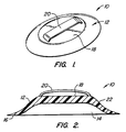
- Figures 1 to 4 show various cup and other constructional features of applictors usable in the embodiments of the invention seen in Figures 4A and 5, and Figures 6 and 7 show how they may best be used.
- the device 10 comprises a vacuum cup body 12 having a concave interior 14 which opens into a lower surface defined by a peripheral lip 16.
- the vacuum cup 12 has a substantially flat upper surface 18 having a strap 20 extending thereacross.
- the strap 20 is firmly secured to the upper surface so that a user can place one or both hands beneath the strap with the hand(s) being open to press directly against the upper surface.
- the vacuum cup body 12 is relatively thick across its flat upper surface and tapers down to form a skirt 22 terminating at the periphery of lip 16.
- the thick upper surface region provides sufficient rigidity so that the applicator body 12 will not involute or "cave in” as the user presses against the upper surface. Instead, the lip 16 and skirt 22 will tend to spread outward reducing the volume of air in the concave interior 14 and providing the desired vacuum.
- the vacuum cup 12 will transmit sufficient force to compress the patient's chest by a desired amount, typically 3.5 to 5 cm. After the desired compression of the chest is completed, the user will lift on the applicator body 12 by raising one or both hands which in turn lift through the strap 20.
- the reduced pressure within the concave interior 14 will cause a vacuum or suction which acts to raise the patient's chest and actively expand the intrathoracic cavity.
- the performer is able to perform CPR in a manner similar to conventional manual CPR, with reduced exposure to injury since the application of force is localized to the intended region on the patient's chest with the position being "anchored" by the device itself. Additionally, the ability to actively raise the patient's chest and expand the intrathoracic cavity provides for improved ventilation and circulation of the patient.
- the applicator device 50 includes a relatively rigid upper plate 52 and a depending vacuum cup structure 54 formed from a relatively resilient material, i.e., a material which is able to spring back.
- a mitten 56 is secured to the upper surface of plate 52 and is shaped to receive a performer's hand.
- An electrode 58 is disposed in the lip 60 of the vacuum cup 54. The electrode is interconnected to a cord 60 intended for hook-up to conventional ECM and/or defibrillation equipment.
- the use of the rigid upper plate 52 helps assure the even application of force to the patient's chest.
- Use of the vacuum cup structure 54 provides for an entrapped cushion of air in its concave interior, further assuring substantially uniform distribution of pressure to the patient's chest.
- the use or the mitten 56 rather than a strap that has previously been described, helps isolate the performer's hand from the other electrodes being used for ECM and/or defibrillation.
- Fig. 4A illustrates first embodiment of the invention with an applicator 150 having a bellows or accordian configuration.
- applicator 150 comprises an applicator body 152 having a handle 154 secured on an upper surface 156.
- the applicator body 152 includes an upper pleated section 158 and a lower skirt section 160 which together define the desired bellows construction.
- the bellows structure may include additional pleated sections, although usually the structure illustrated will be sufficient.
- the applicator body 156 will usually be composed of a resilient elastic material, such as a natural rubber or synthetic rubber, and may be formed by conventional molding techniques.
- the applicator body 156 provides a vacuum cup which permits significant air intrusion or leakage to take place before the desired vacuum is lost.
- applicator device 70 comprising an applicator body 72 and a handle 74 attached to the upper surface of the applicator body 72, is illustrated in Fig. 5.
- the applicator body 72 is illustrated as a vacuum cup, similar to that illustrated in Figs. 1 and 2, but could be any of the other applicator body structures described herein.
- the use of an elongate handle 74 with the applicator body 72 is desirable for patient's lying on the floor or ground.
- a T-bar 76 on the handle 74 allows the performer to stand over the patient with one leg straddled on each side of the patient's chest, applying successive downward and upward strokes to compress and actively expand the chest.
- the handle interferes with the performer's ability to feel and regulate the pressure and compression being applied to the chest. For that reason, it is desirable to provide feedback information, such as a pressure gauge 78, on the handled device 70.
- the pressure gauge employs a spring 80 which is disposed between the T-bar 76 and the fixed portion of handle 74.
- the spring 80 also acts as a shock-absorber which helps limit excessive force applied to the patient.
- Other pressure measuring devices and transducers would also be suitable.
- Patient status information includes minute ventilation, temperature, blood pressure, heart rate, respiratory rate, and other vital signs. Such status information will often require separate monitoring devices (not illustrated) attached to the patient, and the display on the handle makes the information immediately available to the person performing the CPR.
- Feedback information includes pressure or force applied to the patient, depth of compression, compression rate (i.e., cycles per minute), duty cycle (i.e., portion of each cycle in which the patient is compressed), and the like.
- Such feedback information can be provided as discrete values, e.g., with gauges or digital readouts, or may be provided with a light or sound system which indicates when certain threshold values have been met or exceeded. It may be further desirable to provide a pacing signal, e.g., either a sound or flashing light, to facilitate maintaining a desired compression rate.
- a pacing signal e.g., either a sound or flashing light
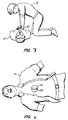
- a method for applying manual CPR using the applicator device 10 is illustrated.
- a patient P suffering from cardiac arrest and apnea is laid on his back on a flat surface and the shirt and collar loosened to provide access to the chest.
- the device 10 is placed over the lower portion of the patient's sternum in the region where conventional CPR is applied (Fig. 7).
- the performer then places one or both hands under the strap 20 of device 10 and begins external chest compressions at a rate of from 80 to 100 per minute.
- the performer will periodically apply mouth-to-mouth resuscitation or other ventilation in order to ventilate the patient. It is an advantage of the present method, however, that the number of ventilations which must be performed is reduced.
- Each chest compression should achieve a compression in the range from about 3.5 to 5 cm, and will be followed by a positive lifting on the chest by the performer by lifting on the applicator device 10. The chest will be lifted and allowed to remain ventilated until the next compression step.
- the compression portion of the cycle will last from about 0.2 to 0.7 seconds, while the expansion portion of the cycle will last from about 0.2 to 0.7 seconds, with the compression and expansion portions usually being equal.
- the method as described above, will be continued until heartbeat and respiration are restored or until medical support arrives.
Landscapes
- Health & Medical Sciences (AREA)
- Heart & Thoracic Surgery (AREA)
- Cardiology (AREA)
- Pain & Pain Management (AREA)
- Pulmonology (AREA)
- Epidemiology (AREA)
- Emergency Medicine (AREA)
- Physical Education & Sports Medicine (AREA)
- Rehabilitation Therapy (AREA)
- Life Sciences & Earth Sciences (AREA)
- Animal Behavior & Ethology (AREA)
- General Health & Medical Sciences (AREA)
- Public Health (AREA)
- Veterinary Medicine (AREA)
- Percussion Or Vibration Massage (AREA)
Description
Claims (11)
- A device (150,70,90) for performing cardiopulmonary resuscitation of a patient, the device having an applicator body (152,72,92) in the form of a cup with a base (156), lip and skirt (158,160), said applicator body having means on its upper surface for applying pressure to the body for transmission through the applicator body to depress the thoracic region of the patient,the base (156) being connected to said lip and skirt so as to transmit and distribute an upward force acting through said means over said lip and skirt (152,72,92)the base being less flexible than the lip and skirt, the lip of the cup being applicable to the region of the sternum of and being sealable to the patient for adherence to the patient whereby the base acting through said applicator body (152,72,92) may be used to raise the sternum of the patient
characterised in that the said means on its upper surface is a manual handle (154,74,76) and there is a display (78) for patient status and/or feedback information mounted on the handle (74,76). - A device (150;70;90) as in claim 1, wherein the display provides information relating to minute ventilation, temperature, blood pressure, heart rate, or respiratory rate.
- A device (150;70;90) as in claim 1, wherein the display provides information relating to compressive force, depth of compression, compression rate, or duty cycle.
- A device according to any one of claims 1 to 3 wherein the lip is of a shape such that the line of contact between patient and device is circular with a diameter in the range 8-25 cm.
- A device according to any one of the preceding claims wherein the the lip is of such a shape that the line of contact between patient and device is circular with a diameter in the range 10-20 cm.
- A device according to any one of the preceding claims wherein the applicator body is of such a shape that when in position for use and no force is applied to the applicator, the distance between patient and base(156) is in the range 5-12cm.
- A device according to any one of the preceding claims, wherein a portion of the lip is coated with an adhesive.
- A device according to any one of the preceding claims, wherein the base of the cup has a generally flat upper surface.
- A device according to any one of the preceding claims, wherein the lower lip is contoured to conform to the patient's chest.
- A device according to any one of the preceding claims, wherein the skirt (158,160) is in the form of a bellows.
- A device as in any one of the preceding claims, further comprising an electrode disposed on the lower surface of the applicator body so that it will contact the patient's chest when the lower surface of the applicator body is adhered thereto.
Applications Claiming Priority (2)
| Application Number | Priority Date | Filing Date | Title |
|---|---|---|---|
| US68654291A | 1991-04-17 | 1991-04-17 | |
| US686542 | 1991-04-17 |
Publications (2)
| Publication Number | Publication Date |
|---|---|
| EP0509773A1 EP0509773A1 (en) | 1992-10-21 |
| EP0509773B1 true EP0509773B1 (en) | 1998-01-07 |
Family
ID=24756739
Family Applications (1)
| Application Number | Title | Priority Date | Filing Date |
|---|---|---|---|
| EP92303367A Expired - Lifetime EP0509773B1 (en) | 1991-04-17 | 1992-04-15 | Device for external chest compression |
Country Status (7)
| Country | Link |
|---|---|
| US (1) | US5454779A (en) |
| EP (1) | EP0509773B1 (en) |
| JP (1) | JP2912762B2 (en) |
| AU (1) | AU651189B2 (en) |
| CA (1) | CA2066297C (en) |
| DE (1) | DE69223840T2 (en) |
| ES (1) | ES2112298T3 (en) |
Cited By (2)
| Publication number | Priority date | Publication date | Assignee | Title |
|---|---|---|---|---|
| DE102012024672A1 (en) | 2012-12-18 | 2014-06-18 | Dräger Medical GmbH | Respirator and method of operating a ventilator |
| US9107800B2 (en) | 2002-03-21 | 2015-08-18 | Physio-Control, Inc. | Front part for support structure for CPR |
Families Citing this family (115)
| Publication number | Priority date | Publication date | Assignee | Title |
|---|---|---|---|---|
| US5645522A (en) * | 1991-04-17 | 1997-07-08 | The Regents Of The University Of California | Devices and methods for controlled external chest compression |
| DE9209296U1 (en) * | 1992-07-10 | 1992-09-24 | Fuchs, Carl-Günter, Dr.med., 37619 Bodenwerder | Suction pressure device for cardiopulmonary resuscitation |
| US5490820A (en) * | 1993-03-12 | 1996-02-13 | Datascope Investment Corp. | Active compression/decompression cardiac assist/support device and method |
| US6425393B1 (en) | 1993-11-09 | 2002-07-30 | Cprx Llc | Automatic variable positive expiratory pressure valve and methods |
| US5551420A (en) * | 1993-11-09 | 1996-09-03 | Cprx, Inc. | CPR device and method with structure for increasing the duration and magnitude of negative intrathoracic pressures |
| US5692498A (en) | 1993-11-09 | 1997-12-02 | Cprx, Inc. | CPR device having valve for increasing the duration and magnitude of negative intrathoracic pressures |
| US7195012B2 (en) | 2003-04-28 | 2007-03-27 | Advanced Circulatory Systems, Inc. | Systems and methods for reducing intracranial pressure |
| US7082945B2 (en) | 2003-04-28 | 2006-08-01 | Advanced Circulatory Systems, Inc. | Ventilator and methods for treating head trauma |
| US6062219A (en) | 1993-11-09 | 2000-05-16 | Cprx Llc | Apparatus and methods for assisting cardiopulmonary resuscitation |
| US7195013B2 (en) | 1993-11-09 | 2007-03-27 | Advanced Circulatory Systems, Inc. | Systems and methods for modulating autonomic function |
| US6604523B2 (en) | 1993-11-09 | 2003-08-12 | Cprx Llc | Apparatus and methods for enhancing cardiopulmonary blood flow and ventilation |
| US5630789A (en) * | 1994-10-07 | 1997-05-20 | Datascope Investment Corp. | Active compression/decompression device for cardiopulmonary resuscitation |
| US5743864A (en) * | 1995-06-29 | 1998-04-28 | Michigan Instruments, Inc. | Method and apparatus for performing cardio-pulmonary resuscitation with active reshaping of chest |
| US5820572A (en) * | 1995-11-21 | 1998-10-13 | The Penn State Research Foundation | Negative pressure chest brace |
| US6533739B1 (en) * | 1995-11-21 | 2003-03-18 | The Penn State Research Foundation | Chest brace and method of using same |
| US5730122A (en) * | 1996-11-12 | 1998-03-24 | Cprx, Inc. | Heart failure mask and methods for increasing negative intrathoracic pressures |
| US6174295B1 (en) | 1998-10-16 | 2001-01-16 | Elroy T. Cantrell | Chest mounted cardio pulmonary resuscitation device and system |
| WO1999024114A1 (en) | 1997-11-06 | 1999-05-20 | Heartstream, Inc. | External defibrillator with cpr prompts and acls prompts and method of use |
| US6224548B1 (en) * | 1998-05-26 | 2001-05-01 | Ineedmd.Com, Inc. | Tele-diagnostic device |
| US6312399B1 (en) | 1998-06-11 | 2001-11-06 | Cprx, Llc | Stimulatory device and methods to enhance venous blood return during cardiopulmonary resuscitation |
| US6234985B1 (en) | 1998-06-11 | 2001-05-22 | Cprx Llc | Device and method for performing cardiopulmonary resuscitation |
| US6463327B1 (en) | 1998-06-11 | 2002-10-08 | Cprx Llc | Stimulatory device and methods to electrically stimulate the phrenic nerve |
| US6155257A (en) * | 1998-10-07 | 2000-12-05 | Cprx Llc | Cardiopulmonary resuscitation ventilator and methods |
| US6390996B1 (en) * | 1998-11-09 | 2002-05-21 | The Johns Hopkins University | CPR chest compression monitor |
| US6171267B1 (en) | 1999-01-07 | 2001-01-09 | Michigan Instruments, Inc. | High impulse cardiopulmonary resuscitator |
| NO311746B1 (en) * | 1999-08-27 | 2002-01-21 | Laerdal Medical As | System for reducing signal interference in ECG caused by cardiac lung rescue |
| US7335085B2 (en) * | 1999-10-13 | 2008-02-26 | Lyman Daniel F | Entertainment and stress relief disk |
| WO2001056652A1 (en) * | 2000-02-04 | 2001-08-09 | Zmd Corporation | Integrated resuscitation |
| US20050131465A1 (en) | 2000-02-04 | 2005-06-16 | Freeman Gary A. | Integrated resuscitation |
| CA2403816A1 (en) | 2000-03-22 | 2001-09-27 | Todd M. Zielinski | Cpr mask with compression timing metronome and methods |
| US6477430B1 (en) | 2001-07-20 | 2002-11-05 | Koninklijke Philips Electronics N.V. | Hands-free paddles using single-use adhesive pads |
| US6776156B2 (en) | 2001-09-28 | 2004-08-17 | Advanced Circulatory Systems, Inc. | Systems and methods to facilitate the delivery of drugs |
| US7682312B2 (en) | 2002-09-20 | 2010-03-23 | Advanced Circulatory Systems, Inc. | System for sensing, diagnosing and treating physiological conditions and methods |
| US6863656B2 (en) | 2002-09-20 | 2005-03-08 | Advanced Circulatory Systems, Inc. | Stress test devices and methods |
| US6827695B2 (en) | 2002-10-25 | 2004-12-07 | Revivant Corporation | Method of determining depth of compressions during cardio-pulmonary resuscitation |
| US20040162510A1 (en) | 2003-02-14 | 2004-08-19 | Medtronic Physio-Control Corp | Integrated external chest compression and defibrillation devices and methods of operation |
| US7044128B2 (en) | 2003-04-08 | 2006-05-16 | Advanced Circulatory Systems, Inc. | CPR demonstration device and methods |
| US7836881B2 (en) | 2003-04-28 | 2010-11-23 | Advanced Circulatory Systems, Inc. | Ventilator and methods for treating head trauma and low blood circulation |
| EP3064242A1 (en) | 2003-04-28 | 2016-09-07 | Advanced Circulatory Systems Inc. | Ventilator and methods for treating head trauma and low blood circulation |
| US7766011B2 (en) | 2003-04-28 | 2010-08-03 | Advanced Circulatory Systems, Inc. | Positive pressure systems and methods for increasing blood pressure and circulation |
| US7226427B2 (en) | 2003-05-12 | 2007-06-05 | Jolife Ab | Systems and procedures for treating cardiac arrest |
| US20050143768A1 (en) * | 2003-06-17 | 2005-06-30 | Samuel Shiber | Sleeved guidewire system method of use |
| US7190999B2 (en) * | 2003-06-27 | 2007-03-13 | Zoll Medical Corporation | Cardio-pulmonary resuscitation device with feedback from measurement of pulse and/or blood oxygenation |
| US8011367B2 (en) | 2003-09-11 | 2011-09-06 | Advanced Circulatory Systems, Inc. | CPR devices and methods utilizing a continuous supply of respiratory gases |
| US6938618B2 (en) | 2003-09-11 | 2005-09-06 | Advanced Circulatory Systems, Inc. | Bag-valve resuscitation for treatment of hypotention, head trauma, and cardiac arrest |
| US20050101889A1 (en) | 2003-11-06 | 2005-05-12 | Freeman Gary A. | Using chest velocity to process physiological signals to remove chest compression artifacts |
| JP2012091021A (en) | 2003-11-06 | 2012-05-17 | Zoll Medical Corp | Device for analyzing physiological signal during application of chest compression |
| US7734344B2 (en) | 2003-12-02 | 2010-06-08 | Uab Research Foundation | Methods, systems and computer program products to inhibit ventricular fibrillation during cardiopulmonary resuscitation |
| US7565194B2 (en) | 2004-05-12 | 2009-07-21 | Zoll Medical Corporation | ECG rhythm advisory method |
| WO2005112749A1 (en) | 2004-05-12 | 2005-12-01 | Zoll Medical Corporation | Ecg rhythm advisory method |
| US7211056B2 (en) * | 2004-08-28 | 2007-05-01 | Danuta Grazyna Petelenz | Device for chest and abdominal compression CPR |
| US8939922B2 (en) * | 2005-02-15 | 2015-01-27 | Laerdal Medical As | Standalone system for assisting in a life-saving situation |
| US7650181B2 (en) | 2005-09-14 | 2010-01-19 | Zoll Medical Corporation | Synchronization of repetitive therapeutic interventions |
| DE202005019670U1 (en) * | 2005-12-14 | 2006-04-27 | Riesinger, Birgit | Wound treatment device with elastically deformable negative pressure generating element |
| US9028259B2 (en) | 2007-01-16 | 2015-05-12 | Physio-Control, Inc. | Wearable CPR assist, training and testing device |
| US8151790B2 (en) | 2007-04-19 | 2012-04-10 | Advanced Circulatory Systems, Inc. | Volume exchanger valve system and method to increase circulation during CPR |
| US9352111B2 (en) | 2007-04-19 | 2016-05-31 | Advanced Circulatory Systems, Inc. | Systems and methods to increase survival with favorable neurological function after cardiac arrest |
| US8622940B2 (en) * | 2008-01-02 | 2014-01-07 | University Of Florida Research Foundation, Inc. | Device for assisting cardiac pulmonary resuscitation |
| US8702633B2 (en) * | 2010-02-12 | 2014-04-22 | Advanced Circulatory Systems, Inc. | Guided active compression decompression cardiopulmonary resuscitation systems and methods |
| US12016820B2 (en) | 2010-02-12 | 2024-06-25 | Zoll Medical Corporation | Enhanced guided active compression decompression cardiopulmonary resuscitation systems and methods |
| US9724266B2 (en) | 2010-02-12 | 2017-08-08 | Zoll Medical Corporation | Enhanced guided active compression decompression cardiopulmonary resuscitation systems and methods |
| US8535251B1 (en) | 2011-04-04 | 2013-09-17 | Subhakar Patthi Rao | Mechanical device to assist in the external compression of the chest during cardio-pulmonary resuscitation |
| US9119767B2 (en) | 2011-09-13 | 2015-09-01 | Harrill D. Wood | Manual CPR or CCC continuous chest compression assist device |
| AU2012358977A1 (en) | 2011-12-19 | 2014-07-24 | ResQSystems, Inc. | Systems and methods for therapeutic intrathoracic pressure regulation |
| US8942800B2 (en) | 2012-04-20 | 2015-01-27 | Cardiac Science Corporation | Corrective prompting system for appropriate chest compressions |
| US9811634B2 (en) | 2013-04-25 | 2017-11-07 | Zoll Medical Corporation | Systems and methods to predict the chances of neurologically intact survival while performing CPR |
| US20140323928A1 (en) | 2013-04-30 | 2014-10-30 | Zoll Medical Corporation | Compression Depth Monitor with Variable Release Velocity Feedback |
| US9662258B2 (en) * | 2013-05-21 | 2017-05-30 | N.M. Beale Company, Inc. | Patient colonoscopy abdominal compression device and method |
| US20140358047A1 (en) | 2013-05-30 | 2014-12-04 | ResQSystems, Inc. | End-tidal carbon dioxide and amplitude spectral area as non-invasive markers of coronary perfusion pressure and arterial pressure |
| KR101445978B1 (en) * | 2013-07-09 | 2014-10-01 | (주)나눔테크 | Education system of Cardiopulmonary Resuscitation |
| US20150088016A1 (en) | 2013-09-25 | 2015-03-26 | Zoll Medical Corporation | Mobile Device Control |
| US9220443B2 (en) * | 2013-10-31 | 2015-12-29 | Zoll Medical Corporation | CPR chest compression monitor for infants |
| US10265495B2 (en) | 2013-11-22 | 2019-04-23 | Zoll Medical Corporation | Pressure actuated valve systems and methods |
| US9750661B2 (en) | 2014-02-19 | 2017-09-05 | Keith G. Lurie | Systems and methods for head up cardiopulmonary resuscitation |
| US10350137B2 (en) | 2014-02-19 | 2019-07-16 | Keith G. Lurie | Elevation timing systems and methods for head up CPR |
| US9707152B2 (en) | 2014-02-19 | 2017-07-18 | Keith G. Lurie | Systems and methods for head up cardiopulmonary resuscitation |
| US12144777B2 (en) | 2014-02-19 | 2024-11-19 | Resuscitation Innovations Llc | Methods and systems to reduce brain damage |
| US11259988B2 (en) | 2014-02-19 | 2022-03-01 | Keith G. Lurie | Active compression decompression and upper body elevation system |
| US11020314B2 (en) | 2014-02-19 | 2021-06-01 | Keith G. Lurie | Methods and systems to reduce brain damage |
| US10406068B2 (en) | 2014-02-19 | 2019-09-10 | Keith G. Lurie | Lockable head up cardiopulmonary resuscitation support device |
| US11246794B2 (en) | 2014-02-19 | 2022-02-15 | Keith G. Lurie | Systems and methods for improved post-resuscitation recovery |
| US11844742B2 (en) | 2014-02-19 | 2023-12-19 | Keith G. Lurie | Methods and systems to reduce brain damage |
| US10667987B2 (en) | 2014-02-19 | 2020-06-02 | Keith G. Lurie | Uniform chest compression CPR |
| US11096861B2 (en) | 2014-02-19 | 2021-08-24 | Keith G. Lurie | Systems and methods for gravity-assisted cardiopulmonary resuscitation and defibrillation |
| US9801782B2 (en) | 2014-02-19 | 2017-10-31 | Keith G. Lurie | Support devices for head up cardiopulmonary resuscitation |
| US10406069B2 (en) | 2014-02-19 | 2019-09-10 | Keith G. Lurie | Device for elevating the head and chest for treating low blood flow states |
| US10245209B2 (en) | 2014-02-19 | 2019-04-02 | Keith G. Lurie | Systems and methods for gravity-assisted cardiopulmonary resuscitation |
| CN105106003A (en) * | 2014-05-20 | 2015-12-02 | 北京德美瑞医疗设备有限公司 | Glove-type abdominal compression CPR (cardiopulmonary resuscitation) device |
| JP2015221159A (en) * | 2014-05-23 | 2015-12-10 | 日本光電工業株式会社 | Cardiopulmonary resuscitation assisting device |
| US11246796B2 (en) | 2014-06-06 | 2022-02-15 | Physio-Control, Inc. | Adjustable piston |
| US12533291B2 (en) | 2014-06-06 | 2026-01-27 | Physio-Control, Inc. | Adjustable piston |
| US10004662B2 (en) | 2014-06-06 | 2018-06-26 | Physio-Control, Inc. | Adjustable piston |
| US10092464B2 (en) | 2014-10-03 | 2018-10-09 | Physio-Control, Inc. | Medical device stabilization strap |
| US10772793B2 (en) | 2015-06-12 | 2020-09-15 | Norman A. Paradis | Mechanical cardiopulmonary resuscitation combining circumferential constriction and anteroposterior compression of the chest |
| EP3362143B1 (en) | 2015-10-16 | 2023-09-27 | Zoll Medical Corporation | Dual sensor electrodes for providing enhanced resuscitation feedback |
| US11684542B2 (en) | 2016-07-22 | 2023-06-27 | Norman A. Paradis | Method to increase the efficacy of cardiopulmonary resuscitation by means of alternating phases during which the physical characteristics of chest compression are varied so as to increase overall forward blood flow |
| US10780020B2 (en) | 2016-09-30 | 2020-09-22 | Zoll Medical Corporation | Maintaining active compression decompression device adherence |
| CN110997028B (en) | 2017-02-22 | 2022-12-30 | 康奈尔大学 | Mechanical vacuum dressing for mechanical management, protection and aspiration of small incision wounds |
| US10415220B2 (en) | 2017-07-06 | 2019-09-17 | Jean Andre Piquant | Technologies for plunging |
| US11179293B2 (en) | 2017-07-28 | 2021-11-23 | Stryker Corporation | Patient support system with chest compression system and harness assembly with sensor system |
| US10590638B2 (en) * | 2017-09-17 | 2020-03-17 | Syneco, LLC | Toilet plunger |
| EP3720518B1 (en) | 2017-12-06 | 2024-09-04 | Cornell University | Manually-operated negative pressure wound therapy (npwt) bandage with improved pump efficiency, automatic pressure indicator and automatic pressure limiter |
| JP2021506466A (en) | 2017-12-21 | 2021-02-22 | ルーリー、キース ジー.LURIE, Keith G. | A device for raising the head and chest to treat low blood flow conditions |
| US11679059B2 (en) | 2017-12-30 | 2023-06-20 | Cpr Therapeutics, Inc. | Methods and devices to improve the efficacy of mechanical cardiopulmonary resuscitation by changing the position of chest compression |
| US12465778B2 (en) | 2018-07-17 | 2025-11-11 | Norman Alan Paradis | Multimodal device and method to increase the efficacy of transthoracic cardioversion or cardiac pacing in patients with perfusing rhythms |
| EP3823719A4 (en) | 2018-07-17 | 2022-11-09 | Paradis, Norman Alan | AUTOMATED RESUSCITATION SYSTEM INTEGRATING HEMODYNAMIC AND DEFIBRILLATION CAPABILITIES |
| CN113632175B (en) | 2019-01-31 | 2026-03-17 | Zoll医疗公司 | Systems and methods for determining compression depth and providing feedback during active compression decompression. |
| KR102264172B1 (en) * | 2019-10-29 | 2021-06-11 | 정지은 | Integral Pad for Automated External Defibrillator |
| CN111249130B (en) * | 2020-02-19 | 2022-04-29 | 山东省立医院 | Hand cardiopulmonary resuscitation emergency treatment device of drowning |
| EP4648059A3 (en) | 2020-09-04 | 2025-12-24 | ZOLL Medical Corporation | Medical treatment system with companion device |
| CN114557875A (en) * | 2022-03-07 | 2022-05-31 | 中国医科大学附属盛京医院 | A negative pressure hand fixing device for assisting thorax expansion promotes respiratory training |
| US12390392B2 (en) | 2022-06-02 | 2025-08-19 | Lee Pietrangelo | Chest compression assist glove |
| USD1053502S1 (en) | 2022-06-02 | 2024-12-10 | Lee Pietrangelo | Chest compression assist glove |
| KR102877144B1 (en) * | 2024-01-16 | 2025-10-27 | 티에프메디칼 주식회사 | Manual cardiopulmonary resuscitation device |
| TR2024005603A1 (en) * | 2024-05-08 | 2025-09-22 | Hitit Ueniversitesi Rektoerluegue | RESUSCITATION APPARATUS |
Family Cites Families (41)
| Publication number | Priority date | Publication date | Assignee | Title |
|---|---|---|---|---|
| US517481A (en) * | 1894-04-03 | Device for producing respiration | ||
| US728003A (en) * | 1902-06-14 | 1903-05-12 | Charles Pfanschmidt | Massage-cup. |
| US1175671A (en) * | 1915-06-21 | 1916-03-14 | Thomas Engleman Acklen | Resuscitator. |
| US1460927A (en) * | 1922-03-28 | 1923-07-03 | Ralph S Thompson | Vacuum cup |
| GB201496A (en) * | 1922-04-28 | 1923-07-30 | Plantation Rubber Mfg Company | Improvements in or relating to scrubbers or like pads |
| FR601773A (en) * | 1925-05-06 | 1926-03-08 | Toothbrush | |
| GB274306A (en) * | 1926-09-17 | 1927-07-21 | Beatrice Evelyn Thomlinson | Improved appliance for massaging the body |
| DE468358C (en) * | 1927-02-08 | 1928-11-12 | Fritz Kuhn Dr | Device for deep pressure massage of the abdominal organs for self-application |
| DE620594C (en) * | 1934-03-24 | 1935-10-24 | Hans Hans Dr | Resuscitation device |
| US2069449A (en) * | 1934-05-01 | 1937-02-02 | Carl F Jensen | Hand protector |
| US2029951A (en) * | 1934-07-16 | 1936-02-04 | Janet Smith E | Polish compact |
| US2071365A (en) * | 1934-11-27 | 1937-02-23 | Pad Y Wax Company Inc | Wax applicator and method of making the same |
| US2204738A (en) * | 1938-08-15 | 1940-06-18 | Harry L Swan | Resuscitator |
| US2571606A (en) * | 1948-05-20 | 1951-10-16 | Peterson Esther | Foot mop |
| US2742251A (en) * | 1952-12-30 | 1956-04-17 | Udvardy Zolton | Support for self-massaging device |
| US2879765A (en) * | 1957-06-25 | 1959-03-31 | Paul V Featherston | Therapeutic device |
| US3228392A (en) * | 1963-07-15 | 1966-01-11 | Walter L Speyer | Abdominal exerciser |
| FR1476518A (en) * | 1964-12-30 | 1967-04-14 | Systolo-diastolic prosthesis for external cardiac massage with assisted breathing | |
| GB1187274A (en) * | 1967-04-03 | 1970-04-08 | Matburn Holdings Ltd | Cardiac Massage Apparatus |
| US3460182A (en) * | 1967-08-14 | 1969-08-12 | Joseph A Grande Jr | Cleaning pad |
| US3534733A (en) * | 1968-01-10 | 1970-10-20 | Us Navy | Spring-loaded suction cup-type biomedical instrumentation electrode |
| US3783865A (en) * | 1971-11-08 | 1974-01-08 | Marquette Electronics Inc | Suction electrode |
| US4077400A (en) * | 1975-01-17 | 1978-03-07 | Roy Major Harrigan | External cardiac resuscitation aid |
| US4166458A (en) * | 1975-01-17 | 1979-09-04 | Harrigan Roy Major | External cardiac resuscitation aid |
| US3958564A (en) * | 1975-05-09 | 1976-05-25 | The United States Of America As Represented By The Secretary Of The Navy | EKG contact |
| US4095590A (en) * | 1975-08-29 | 1978-06-20 | Roy Major Harrigan | External cardiac resuscitation aid |
| US4059099A (en) * | 1976-04-13 | 1977-11-22 | Davis Belford L | Resuscitative device |
| FR2382889A1 (en) * | 1977-03-07 | 1978-10-06 | Bloch Laroque Paul | Resuscitation apparatus for medical use - has suction pistons operated in cylinder to provide cardiac message and assisted respiration |
| US4273114A (en) * | 1978-10-19 | 1981-06-16 | Michigan Instruments, Inc. | Cardiopulmonary resuscitator, defibrillator and monitor |
| US4198963A (en) * | 1978-10-19 | 1980-04-22 | Michigan Instruments, Inc. | Cardiopulmonary resuscitator, defibrillator and monitor |
| US4196722A (en) * | 1979-01-05 | 1980-04-08 | Vanderwoude Carol A | Percussion instrument used in respiratory therapy |
| US4237872A (en) * | 1979-04-30 | 1980-12-09 | Harrigan Roy Major | External cardiac resuscitation aid |
| US4338924A (en) * | 1980-11-20 | 1982-07-13 | Bloom Charles S | Cardiopulmonary resuscitation device |
| US4429688A (en) * | 1980-12-08 | 1984-02-07 | Duffy Peter B | Medical appliance for percussive respiratory therapy |
| GB8316194D0 (en) * | 1983-06-14 | 1983-07-20 | Medeci Developments Ltd | Electrode holders for current therapy |
| JPH0225366Y2 (en) * | 1985-06-06 | 1990-07-12 | ||
| US4747397A (en) * | 1986-06-12 | 1988-05-31 | Magovern George J | Flexible pad for direct myocardial tissue massage having thumb loop |
| US4745910A (en) * | 1987-04-08 | 1988-05-24 | Ballard Medical Products | Percussor to aid in removal of lung secretions, and methods |
| US4881527A (en) * | 1988-11-14 | 1989-11-21 | Lerman Samuel I | Cardiac assist cuirass |
| US4984987A (en) * | 1989-11-09 | 1991-01-15 | Actar Airforce, Inc. | CPR manikin |
| US5295481A (en) * | 1991-11-01 | 1994-03-22 | Geeham Calvin T | Cardiopulmonary resuscitation assist device |
-
1992
- 1992-04-13 AU AU14877/92A patent/AU651189B2/en not_active Expired
- 1992-04-15 EP EP92303367A patent/EP0509773B1/en not_active Expired - Lifetime
- 1992-04-15 DE DE69223840T patent/DE69223840T2/en not_active Expired - Lifetime
- 1992-04-15 ES ES92303367T patent/ES2112298T3/en not_active Expired - Lifetime
- 1992-04-16 CA CA002066297A patent/CA2066297C/en not_active Expired - Lifetime
- 1992-04-17 JP JP4097582A patent/JP2912762B2/en not_active Expired - Fee Related
-
1994
- 1994-04-12 US US08/226,431 patent/US5454779A/en not_active Expired - Lifetime
Cited By (3)
| Publication number | Priority date | Publication date | Assignee | Title |
|---|---|---|---|---|
| US9107800B2 (en) | 2002-03-21 | 2015-08-18 | Physio-Control, Inc. | Front part for support structure for CPR |
| DE102012024672A1 (en) | 2012-12-18 | 2014-06-18 | Dräger Medical GmbH | Respirator and method of operating a ventilator |
| US10695526B2 (en) | 2012-12-18 | 2020-06-30 | Drägerwerk AG & Co. KGaA | Ventilation system |
Also Published As
| Publication number | Publication date |
|---|---|
| DE69223840D1 (en) | 1998-02-12 |
| JPH05111521A (en) | 1993-05-07 |
| ES2112298T3 (en) | 1998-04-01 |
| US5454779A (en) | 1995-10-03 |
| AU651189B2 (en) | 1994-07-14 |
| CA2066297A1 (en) | 1992-10-18 |
| CA2066297C (en) | 2000-09-05 |
| EP0509773A1 (en) | 1992-10-21 |
| AU1487792A (en) | 1992-10-22 |
| JP2912762B2 (en) | 1999-06-28 |
| DE69223840T2 (en) | 1998-07-30 |
Similar Documents
| Publication | Publication Date | Title |
|---|---|---|
| US5454779A (en) | Devices and methods for external chest compression | |
| US5645522A (en) | Devices and methods for controlled external chest compression | |
| EP2900194B1 (en) | Cardiopulmonary resuscitation device | |
| US11123261B2 (en) | Enhanced guided active compression decompression cardiopulmonary resuscitation systems and methods | |
| US4059099A (en) | Resuscitative device | |
| US8702633B2 (en) | Guided active compression decompression cardiopulmonary resuscitation systems and methods | |
| US8622940B2 (en) | Device for assisting cardiac pulmonary resuscitation | |
| EP1622562B1 (en) | System for treating cardiac arrest | |
| AU748550B2 (en) | A device for assisted cardiopulmonary resuscitation | |
| US7361151B2 (en) | Device and kit for assisting in cardiopulmonary resuscitations | |
| WO2008015623A2 (en) | Cpr coaching device providing tactile feedback | |
| US12016820B2 (en) | Enhanced guided active compression decompression cardiopulmonary resuscitation systems and methods | |
| JP7549169B1 (en) | Chest compression aid | |
| KR102358624B1 (en) | Dummy for cardiopulmonary resuscitation | |
| EP3737348B1 (en) | Equipment for use when giving heart massage | |
| Paul et al. | Design of auto adjustable CPR assistive device for non-expertise usability scenarios | |
| WO2025023873A3 (en) | Autonomous cardiac resuscitation | |
| HU217941B (en) | Revivificating device for ensuring active compression and decompression |
Legal Events
| Date | Code | Title | Description |
|---|---|---|---|
| PUAI | Public reference made under article 153(3) epc to a published international application that has entered the european phase |
Free format text: ORIGINAL CODE: 0009012 |
|
| AK | Designated contracting states |
Kind code of ref document: A1 Designated state(s): AT BE CH DE DK ES FR GB GR IT LI LU MC NL PT SE |
|
| 17P | Request for examination filed |
Effective date: 19930402 |
|
| 17Q | First examination report despatched |
Effective date: 19941025 |
|
| GRAG | Despatch of communication of intention to grant |
Free format text: ORIGINAL CODE: EPIDOS AGRA |
|
| GRAG | Despatch of communication of intention to grant |
Free format text: ORIGINAL CODE: EPIDOS AGRA |
|
| GRAH | Despatch of communication of intention to grant a patent |
Free format text: ORIGINAL CODE: EPIDOS IGRA |
|
| GRAH | Despatch of communication of intention to grant a patent |
Free format text: ORIGINAL CODE: EPIDOS IGRA |
|
| RBV | Designated contracting states (corrected) |
Designated state(s): DE ES FR GB IT |
|
| GRAA | (expected) grant |
Free format text: ORIGINAL CODE: 0009210 |
|
| AK | Designated contracting states |
Kind code of ref document: B1 Designated state(s): DE ES FR GB IT |
|
| REF | Corresponds to: |
Ref document number: 69223840 Country of ref document: DE Date of ref document: 19980212 |
|
| ET | Fr: translation filed | ||
| ITF | It: translation for a ep patent filed | ||
| REG | Reference to a national code |
Ref country code: ES Ref legal event code: FG2A Ref document number: 2112298 Country of ref document: ES Kind code of ref document: T3 |
|
| PLBE | No opposition filed within time limit |
Free format text: ORIGINAL CODE: 0009261 |
|
| STAA | Information on the status of an ep patent application or granted ep patent |
Free format text: STATUS: NO OPPOSITION FILED WITHIN TIME LIMIT |
|
| 26N | No opposition filed | ||
| REG | Reference to a national code |
Ref country code: GB Ref legal event code: IF02 |
|
| PGFP | Annual fee paid to national office [announced via postgrant information from national office to epo] |
Ref country code: ES Payment date: 20110426 Year of fee payment: 20 Ref country code: FR Payment date: 20110504 Year of fee payment: 20 Ref country code: DE Payment date: 20110427 Year of fee payment: 20 |
|
| PGFP | Annual fee paid to national office [announced via postgrant information from national office to epo] |
Ref country code: GB Payment date: 20110426 Year of fee payment: 20 |
|
| PGFP | Annual fee paid to national office [announced via postgrant information from national office to epo] |
Ref country code: IT Payment date: 20110423 Year of fee payment: 20 |
|
| REG | Reference to a national code |
Ref country code: DE Ref legal event code: R071 Ref document number: 69223840 Country of ref document: DE |
|
| REG | Reference to a national code |
Ref country code: DE Ref legal event code: R071 Ref document number: 69223840 Country of ref document: DE |
|
| REG | Reference to a national code |
Ref country code: GB Ref legal event code: PE20 Expiry date: 20120414 |
|
| PG25 | Lapsed in a contracting state [announced via postgrant information from national office to epo] |
Ref country code: DE Free format text: LAPSE BECAUSE OF EXPIRATION OF PROTECTION Effective date: 20120416 |
|
| PG25 | Lapsed in a contracting state [announced via postgrant information from national office to epo] |
Ref country code: GB Free format text: LAPSE BECAUSE OF EXPIRATION OF PROTECTION Effective date: 20120414 |
|
| REG | Reference to a national code |
Ref country code: ES Ref legal event code: FD2A Effective date: 20130711 |
|
| PG25 | Lapsed in a contracting state [announced via postgrant information from national office to epo] |
Ref country code: ES Free format text: LAPSE BECAUSE OF EXPIRATION OF PROTECTION Effective date: 20120416 |