EP0508971B1 - Einfärbevorrichtung zum Drucken auf nichtporösen Oberflächen - Google Patents
Einfärbevorrichtung zum Drucken auf nichtporösen Oberflächen Download PDFInfo
- Publication number
- EP0508971B1 EP0508971B1 EP92850078A EP92850078A EP0508971B1 EP 0508971 B1 EP0508971 B1 EP 0508971B1 EP 92850078 A EP92850078 A EP 92850078A EP 92850078 A EP92850078 A EP 92850078A EP 0508971 B1 EP0508971 B1 EP 0508971B1
- Authority
- EP
- European Patent Office
- Prior art keywords
- roll
- housing
- transfer roll
- housing member
- ink
- Prior art date
- Legal status (The legal status is an assumption and is not a legal conclusion. Google has not performed a legal analysis and makes no representation as to the accuracy of the status listed.)
- Expired - Lifetime
Links
Images


Classifications
-
- B—PERFORMING OPERATIONS; TRANSPORTING
- B41—PRINTING; LINING MACHINES; TYPEWRITERS; STAMPS
- B41K—STAMPS; STAMPING OR NUMBERING APPARATUS OR DEVICES
- B41K3/00—Apparatus for stamping articles having integral means for supporting the articles to be stamped
- B41K3/54—Inking devices
- B41K3/60—Inking devices using rollers, e.g. rollers with integral ink-supply devices
-
- B—PERFORMING OPERATIONS; TRANSPORTING
- B41—PRINTING; LINING MACHINES; TYPEWRITERS; STAMPS
- B41J—TYPEWRITERS; SELECTIVE PRINTING MECHANISMS, i.e. MECHANISMS PRINTING OTHERWISE THAN FROM A FORME; CORRECTION OF TYPOGRAPHICAL ERRORS
- B41J27/00—Inking apparatus
- B41J27/10—Inking apparatus with ink applied by rollers; Ink supply arrangements therefor
- B41J27/12—Rollers
Definitions
- This invention relates to cartridges containing ink rolls for fast drying inks. More particularly, it relates to protective cartridge housings for preventing ink rolls from drying out after contact with quick drying inks.
- Cartridge structures for ink rolls used for inking type characters on a box or other print receiving member are known as described in U. S. Patent 3,785,288.
- ink cartridges are sold commercially for use in conveyor line printers such as Model 100 manufactured by Universal Fountain Brush Co. These cartridges are useful to print on all types of surfaces.
- a problem has occurred in attempts to use the required high volatile inks needed to print on non-porous surfaces such as waxed boxes, plastic films and metalized surfaces.
- the problem is the drying out of the ink rolls caused by the high volatile inks. After standing overnight, the ink roll becomes hard and brittle and in this condition will not transfer ink to the print surface. This necessitates frequent replacement of the ink roll and added expense to the manufacturers.
- An improved cartridge is needed which will prevent the drying out of ink rolls used with high volatile inks.
- My cartridge has a closely fitted top and bottom housing.
- the top housing has an inner wall spaced closely around the ink roll and the transfer roll with a discontinuity in an exterior side wall that is only sufficiently wide to permit less than 90 degrees of the transfer roll outer circumference to be exposed at any one time and the exposed portion of the transfer roll abuts a print die surface on a print drum.
- a like discontinuity in an inner wall of the top housing around the transfer roll at a point distal from the exterior wall discontinuity permits contact with an eccentrically mounted ink roll which supplies a continuous amount of ink to the transfer roll as the transfer roll turns.
- the transfer roll turns by a direct drive from a drive roll frictionally moved by a surface of the print drum moving in response to contact with a printing surface.
- the printing surface is usually on a box moving on a conveyor past the print drum, a continuous web of plastic film or metal foil.
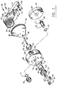
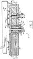
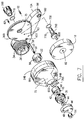
- the inking apparatus 10 of this invention shown in section in FIG. 3 has a mounting base 12, a print drum 14 rotatable on a shaft 16 supported by the base 12, an ink roll 18 rotatable on a shaft 80, an ink transfer roll 22 and a closely fitted top ink housing 24 and bottom ink housing 26 enclosing the ink roll 18 and transfer roll 22.
- the print drum 14 has a rubberized rail 28 around a top portion.
- the rail 28 engages a drive roll 38 and turns the drive roll as the drum 14 turns in response to frictional engagement to a moving print surface (not shown).
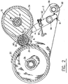
- Print die letters 30 seen in FIG. 2 are press fit into grooves 32 on the print drum 14.
- the transfer roll 22 coats the letters 30 with ink to make an impression on the required print surface.
- the print drum 14 has an interior annular wall 34 and spaced apart from the wall 14 is nut 36 on shaft 16 to hold the print drum 14 in position on base 12.
- the rubberized rail 28 of the print drum 14 turning drive roll 38 is seen in FIG. 3.
- a ball bearing hub 40 located below the drive roll 38 has three upwardly projecting pins 42 engaging with a bottom surface of the drive roll 38 as seen in FIG. 1.
- a washer 44 and a cover 46 are inserted over the drive roll 38.
- a bore 48 through cover 46 receives the top threads 50 from a stud 52 and a knurled knob 54 engages the threads 50 to tighten the drive assembly through the central opening 56 in the transfer roll 22.
- the bottom threads 58 engage threads within a bore 60 in the back housing 26.
- the back housing 26 is held in place over the mounting base 12 on arm 92 by allen screws 62 engaging threads within bores 63.
- the threads on allen screws 62 pass through bore 65 on arm 92.
- Top housing 24 has three bores.
- the first 64 receives the ball bearing hub 40 connected to transfer roll 22 within housing 24.
- a small discontinuity 66 in side wall 68 provides a restricted opening for a small portion of transfer roll 22 to be exposed to the letters 30 on the print drum 14 as the drum moves past the transfer roll 22.
- the interior wall portion 70 of the top housing is spaced closely to the transfer roll 22 with no more than 0.080 of an inch clearance.
- An interior discontinuity 72 in wall surface 70 provides an opening for the transfer roll 22 to contact the ink roll 18.
- the limited exposure to the air of the transfer roll 22 provides a vapor escape route barrier for ink solvent evaporation from the saturated ink roll 18.
- the limited discontinuity 66 in the housing wall 68 and the close spacing between interior wall 70 of the housing 24 and roll 22 prevents evaporation of the volatile ink and dry out of ink roll 18 when not in use.
- the second bore 74 in housing 24 receives a shaft 76 engaged to an adjustment knob 78.
- O-ring 77 mounted on the bottom portion of the shaft 76 and DELRIN® washers 71 and 73 above and below housing 24 provide an air tight seal in bore 74.
- a smaller diameter shaft 80 descending downwardly from shaft 76 engages with a bore 82 in the center of ink roll 18.
- the ink roll 18 turns on shaft 80 and the bottom 19 of roll 18 is spaced apart from the housing back 26.
- the ink roll 18 is enclosed entirely by housing 24.
- a third threaded bore 84 is found in side wall 68 of the housing 24 and is used to thread an ink refill container 86 to housing 24.
- the ink flows by gravity into a ball type exit 88 which directly wets the ink roll 18 with ink on demand. This configuration is used for web printing.
- the bore 84 could be located adjacent bore 74 on a top surface of housing 24 for other types of printing.
- the pressure of the transfer roll 22 on the letters 30 of the print drum 14 is controlled by position adjusting screw 91.
- the tension apparatus 90 is supported by an arm 92, pivotally mounted on base 12 at pivot point 94.
- the inking apparatus 10 of this invention can be mounted to in line manufacturing equipment by a shaft 96 which can be clamped to the in line equipment at a proper height and distance to permit inking of the desired surfaces.
- Support housing 98 maintains alignment of shaft 96 in bore 100 within mounting base 12 as seen in FIG. 6.
- the adjustment knob 78 as shown in FIG. 5 can have an indicator pointer on a top surface to match with a desired tension adjustment reading set forth on a top surface of housing 24.
- a clockwise turning of knob 78 increases the tension on ink roll 18 and causes a heavier flow of ink to the transfer roll 22.
- the bottom ink housing 26A rather than top ink housing 24A, contains a bore 75 for receipt of shaft 76A.
- the bottom portion of the adjustment knob 78A engages shaft 76A projecting through bore 75 with O-ring seal 77A and washers 71A and 73A providing a gas tight seal.
- the side wall 68A, the first bore 64A, the interior wall 70A and the wall discontinuity 66A remain substantially the same. There are no additional bores in housing 24A in this configuration.
- An outside ink supply such as shown in FIG. 4 can be added by making an additional bore in housing 26A.
- Tension between transfer roll surface 22 and dye surface 30 is adjusted by loosening screws 62 and sliding base 26A forward and securing screws 62.
- the base 12A and base housing 26B have a different configuration with 24B, 64B, 66B, 70A, 71B, 73B, 76B, 77B and 80B corresponding to the same elements in FIG. 6.
- the ink used with the inking apparatus described above is a commercial grade of a fast drying volatile ink used for non-porous surfaces such as those on wax cartons.
- the ink roll is usually made from a reticulated neoprene foam and the transfer roll is made from "DELRIN”®, a high strength plastic made by E. I. du Pont de Nemours & Company, Inc.
- the print drum covering is made from a natural rubber with the parallel ridges configured to hold letters or numbers press fit into place.
- the spacing between the transfer roll 22 and the housing wall 70 or 70A is critical and should be in the range of 0,2 to 0,025 cm (0.080 to .010 inches) with about 0,076 cm (.030 inches) being preferred.
- the discontinuity 66 and 66A in the wall 68 or 68A should be about 1,9 cm (three quarters of an inch).
- the ink roll 18 is mounted eccentric to knob 78 and usually 0,158 cm (0.062 inch) from the axial center of housing 24.
- the ink roll 18 is located in a generally annular portion of the housing 24 or 26.
- the transfer roll 22 is located within a lateral projection from an axial centerline of the annular portion of the housing 24.
- the drive mechanism from the print drum to the drive roll is activated by friction to coincide with boxes or web materials moving along a conveyor line or web line in a manufacturing process.
- a neoprene seal can be inserted between the top housing 24 or 24A and the bottom housing 26 or 26A. Such a seal will enhance retention of the volatile inks within the cartridge formed by the housing 24/26, 24A/26A or 24B/26B.
Landscapes
- Impression-Transfer Materials And Handling Thereof (AREA)
- Inking, Control Or Cleaning Of Printing Machines (AREA)
Claims (22)
- Patroneneinheit für eine mit Tinte gefüllte Rolle und eine anliegende Übertragungsrolle, gekennzeichnet durch
ein erstes Gehäuseteil, das fest an einem zweiten Gehäuseteil zur Bildung einer Umschließung für die mit Tinte gefüllte Rolle und die Übertragungsrolle fest angesetzt ist,
entsprechende Bereiche des ersten und des zweiten Gehäuseteils mit einer im allgemeinen ringförmigen Konfiguration,
die die mit Tinte gefüllte Rolle umschließt, mit einer ersten Bohrung, die axial innerhalb der ringförmigen Konfiguration entweder des ersten oder des zweiten Gehäuseteils angeordnet ist, zur Aufnahme einer Welle, um die herum sich die mit Tinte gefüllte Rolle innerhalb der Umschließung aus erstem und zweitem Gehäuseteil dreht,
entsprechende Bereiche des ersten und des zweiten Gehäuseteils mit einem seitlichen, nach außen vorspringenden Bereich mit Hinblick auf die Achse der ersten Bohrung in dem ersten oder dem zweiten Gehäuseteil, wobei der vorspringende Bereich des ersten Gehäuseteils eine Innenwand aufweist, die den Außenumfang der Übertragungsrolle, die innerhalb des vorspringenden Bereichs des ersten Gehäuseteils drehbar angeordnet ist, umschließt und eng von diesem beabstandet ist,
eine Antriebsrolle, die außenseitig des vorspringenden Bereichs des ersten Gehäuseteils drehbar angeordnet ist und axial mit der Übertragungsrolle fluchtet, wobei sich die Übertragungsrolle in Reaktion auf die Drehung der Antriebsrolle dreht,
eine Unterbrechung in der äußeren Seitenwand des vorspringenden Bereichs des ersten Gehäuseteils in der Nähe der Übertragungsrolle und von der Tintenrolle aus distal angeordnet, um eine Freilegung von weniger als 90° des Übertragungsrollenumfangs zu gestatten,
eine Unterbrechung in einer inneren Seitenwand des ersten Gehäuseteils, die von der Unterbrechung in der äußeren Seitenwand distal angeordnet ist, um ein Anliegen der Übertragungsrolle und der mit Tinte gefüllten Rolle innerhalb der Gehäuseumschließung zu gestatten, und
wobei sich die Antriebsrolle in Reaktion auf die Berührung mit einer sich bewegenden Druckrollentrommel dreht. - Patroneneinheit nach Anspruch 1, dadurch gekennzeichnet, daß die erste Bohrung durch eine obere Flächenwand des ersten Gehäuseteils hindurchgehend angeordnet ist.
- Patroneneinheit nach Anspruch 1, dadurch gekennzeichnet, daß die erste Bohrung durch eine Basisflächenwand des zweiten Gehäuseteils hindurchgehend angeordnet ist.
- Patroneneinheit nach Anspruch 1, gekennzeichnet durch eine innerhalb des Zentrums der Übertragungsrolle angeordnete Nabe, wobei die Nabe mittels der Antriebsrolle drehbar ist, und eine in der oberen Fläche des ersten Gehäuseteils innerhalb des vorspringenden Bereichs angeordnete zweite Bohrung, wobei die Übertragungsrolle in der zweiten Bohrung angeordnet ist.
- Patroneneinheit nach Anspruch 4, gekennzeichnet durch einen am ersten und am zweiten Ende mit Gewinde ausgestatteten Zapfen, wobei das erste Ende mit dem zweiten Gehäuseteil verschraubt ist, der Zapfen durch die zweite Bohrung im ersten Gehäuseteil hindurch und durch den Mittelpunkt in der Übertragungsrolle und der Antriebsrolle hindurch angeordnet ist und das zweite Ende des Zapfens mit einem mit Gewinde ausgestatteten Knauf außerhalb der Antriebsrolle in Verbindung steht.
- Patroneneinheit nach Anspruch 5, gekennzeichnet durch einen rund um eine Drucktrommel herum ringförmig angeordneten Steg, wobei die Drucktrommel eine Druckfläche aufweist, die in anliegender Berührung mit dem Bereich der Übertragungsrolle steht, der an der Außenwandunterbrechung freigelegt ist, wobei sich die Antriebsrolle in Reaktion auf die Reibungsberührung mit dem Steg dreht.
- Patroneneinheit nach Anspruch 4, gekennzeichnet durch einen Tintenlieferbehälter zur Ausbildung einer bedarfsweisen Tintenströmung zu der Tintenrolle hin, wobei der Tintenlieferbehälter außenseitige Gewindegänge in einem Basisbereich aufweist, die mit Gewindegängen innerhalb einer im oberen Gehäuse angeordneten dritten Bohrung im Eingriff stehen.
- Patroneneinheit nach Anspruch 1, gekennzeichnet durch Basisteil, das die Drucktrommel abstützt, eine Spanneinrichtung mit einem Spannungseinstellmittel angeordnet am Basisteil und zur Steuerung der Größe des durch die Übertragungsrolle auf einer Druckfläche der Drucktrommel ausgeübten Drucks.
- Patroneneinheit nach Anspruch 1, gekennzeichnet durch ein Basisteil, wobei die Drucktrommel axial an dem Basisteil angebracht ist, und einen Spannungsanbringungsarm, der an dem Basisteil befestigt ist, das die beiden Gehäuseteile trägt.
- Patroneneinheit nach Anspruch 1, dadurch gekennzeichnet, daß der Abstand zwischen dem Außenumfang der Übertragungsrolle und der Innenwand des vorspringenden Bereichs des ersten Gehäuseteils 0,2 bis 0,025 cm (0,080 bis 0,010 Zoll) mißt.
- Patroneneinheit nach Anspruch 10, dadurch gekennzeichnet, daß der Abstand etwa 0,076 cm (0,030 Zoll) mißt.
- Einfärbevorrichtung gekennzeichnet durch
ein eine Drucktrommel an einer vertikalen Welle tragendes Basisteil,
eine an einem an dem Basisteil schwenkbar abgestützten Arm angeordnete Spanneinrichtung,
eine eine mit Tinte gefüllte Rolle und eine anliegende Übertragungsrolle umschließende Patroneneinheit, wobei die Übertragungsrolle an dem Arm angebracht ist,
wobei die Patroneneinheit ein erstes Gehäuseteil aufweist, das an einem zweiten Gehäuseteil zur Bildung einer Umschließung für die mit Tinte gefüllte Rolle und die Übertragungsrolle fest angesetzt ist,
entsprechende Bereiche des ersten und des zweites Gehäuseteils eine im allgemeinen ringförmige Konfiguration, die die mit Tinte gefüllte Rolle umschließt, aufweisen, wobei eine erste Bohrung innerhalb der ringförmigen Konfiguration entweder des ersten oder des zweiten Gehäuseteils zur Aufnahme einer Welle axial angeordnet ist, die die mit Tinte gefüllte Rolle innerhalb der Patroneneinheit drehbeweglich abstützt, entsprechende seitliche, vorspringende Bereiche des ersten und des zweiten Gehäuseteils in der Nähe der ringförmigen Konfiguration, wobei der vorspringende Bereich des ersten Gehäuseteils eine innere Wand aufweist, die in einem engen Abstand von dem Außenumfang der Übertragungsrolle angeordnet ist, die innerhalb des ersten Gehäuseteils drehbar angeordnet ist,
eine Antriebsrolle, die außerhalb des ersten Gehäuseteils angeordnet ist und axial mit der Übertragungsrolle fluchtet, wobei sich die Übertragungsrolle in Reaktion auf die Drehung der Antriebsrolle dreht,
eine Unterbrechung in der äußeren Seitenwand des ersten Gehäuseteils in der Nähe der Übertragungsrolle und von der mit Tinte gefüllten Rolle aus distal angeordnet, um eine Freilegung von weniger als 90° des Übertragungsrollenumfangs zu gestatten,
eine Unterbrechung in der inneren Seitenwand des ersten Gehäuseteils von der Unterbrechung in der äußeren Seitenwand aus distal angeordnet, um eine Anlage der Übertragungsrolle und der mit Tinte gefüllten Rolle innerhalb der Gehäuseumschließung zu gestatten, und wobei sich die Antriebsrolle in Reaktion auf die Berührung mit der sich in einem Bewegungszustand befindenden Drucktrommel dreht. - Einfärbevorrichtung nach Anspruch 12, dadurch gekennzeichnet, daß in der Patroneneinheit die erste Bohrung in einer oberen Flächenwand des ersten Gehäuseteils angeordnet ist.
- Einfärbevorrichtung nach Anspruch 12, dadurch gekennzeichnet, daß in der Patroneneinheit die erste Bohrung durch eine Basisflächenwand des zweiten Gehäuseteils hindurchgehend angeordnet ist.
- Einfärbevorrichtung nach Anspruch 12, gekennzeichnet durch eine innerhalb des Zentrum der Übertragungsrolle angeordneten Nabe, wobei die Übertragungsrolle unter einer zweiten Bohrung in der oberen Fläche des ersten Gehäuseteils innerhalb des seitlichen, vorspringenden Bereichs des oberen Gehäuseteils angeordnet ist und die Nabe durch die Antriebsrolle gedreht wird.
- Einfärbevorrichtung nach Anspruch 15, gekennzeichnet durch eine am ersten und am zweiten Ende mit Gewinde ausgestatteten Zapfen, der an dem ersten Ende mit dem zweiten Gehäuseteil in Verbindung steht, wobei der Zapfen durch die zweite Bohrung in dem ersten Gehäuseteil und durch den Mittelpunkt in der Übertragungsrolle und der Antriebsrolle hindurchgehend angeordnet ist und der Zapfen an dem zweiten Ende mit einem mit Gewinde ausgestatteten Knauf außerhalb der Antriebsrolle in Verbindung steht.
- Einfärbevorrichtung nach Anspruch 16, gekennzeichnet durch eine ringförmig um die Drucktrommel herum angeordneten Steg, wobei die Drucktrommel eine Druckfläche in anliegender Berührung mit dem Bereich der Übergaberolle aufweist, der an der Unterbrechung der äußeren Wand freigelegt ist, wobei sich die Antriebsrolle in Reaktion auf die reibende Berührung mit dem Steg dreht.
- Einfärbevorrichtung nach Anspruch 12, gekennzeichnet durch einen Tintenspeicher, der mit dem ersten Gehäuseteil über eine Gewindebohrung in der Nähe der Tintenrolle in Verbindung steht.
- Einfärbevorrichtung nach Anspruch 12, gekennzeichnet durch einen Tintenspeicher, der mit dem zweiten Gehäuseteil über eine Gewindebohrung in der Nähe der Tintenrolle in Verbindung steht.
- Einfärbevorrichtung nach Anspruch 12, gekennzeichnet durch eine Bohrung in dem Basisteil, die von der die Drucktrommel tragenden Welle aus distal angeordnet ist, wobei die Bohrung eine Anbauwelle enthält, die Anbauwelle mit einer Herstellungsversorgungslinie in Verbindung steht, die Schachteln oder Gewebeflächen enthält, die mittels der Patroneneinheit zu bedrucken sind.
- Einfärbevorrichtung nach Anspruch 12, dadurch gekennzeichnet, daß der Abstand zwischen dem Außenumfang der Übertragungsrolle und der Innenwand des vorspringenden Bereichs des ersten Gehäuseteils 0,2 bis 0,025 cm (0,080 bis 0,010 Zoll) mißt.
- Einfärbevorrichtung nach Anspruch 21, dadurch gekennzeichnet, daß der Abstand etwa 0,076 cm (0,030 Zoll) mißt.
Applications Claiming Priority (2)
| Application Number | Priority Date | Filing Date | Title |
|---|---|---|---|
| US684669 | 1991-04-12 | ||
| US07/684,669 US5109769A (en) | 1991-04-12 | 1991-04-12 | Inking apparatus for printing on non porous surfaces |
Publications (3)
| Publication Number | Publication Date |
|---|---|
| EP0508971A2 EP0508971A2 (de) | 1992-10-14 |
| EP0508971A3 EP0508971A3 (en) | 1993-05-05 |
| EP0508971B1 true EP0508971B1 (de) | 1996-07-03 |
Family
ID=24749058
Family Applications (1)
| Application Number | Title | Priority Date | Filing Date |
|---|---|---|---|
| EP92850078A Expired - Lifetime EP0508971B1 (de) | 1991-04-12 | 1992-04-09 | Einfärbevorrichtung zum Drucken auf nichtporösen Oberflächen |
Country Status (4)
| Country | Link |
|---|---|
| US (1) | US5109769A (de) |
| EP (1) | EP0508971B1 (de) |
| DE (1) | DE69211889T2 (de) |
| ES (1) | ES2089480T3 (de) |
Families Citing this family (5)
| Publication number | Priority date | Publication date | Assignee | Title |
|---|---|---|---|---|
| US5427023A (en) * | 1991-05-20 | 1995-06-27 | Pitney Bowes Inc. | Mailing machine having a disposable inking cartridge |
| US5353700A (en) * | 1991-05-20 | 1994-10-11 | Pitney Bowes Inc. | Mailing machine including movable inking cartridge |
| USD339819S (en) | 1991-11-13 | 1993-09-28 | Jianq Shuay Rubber Exploit Inc. | Rollable stamp |
| DE9315606U1 (de) * | 1993-10-08 | 1993-12-23 | Bär, Edeltraud, 74821 Mosbach | Druckvorrichtung, insbesondere Kodier- oder Prägevorrichtung zum Bedrucken eines Mediums |
| JP4745992B2 (ja) * | 2007-02-23 | 2011-08-10 | 株式会社サトー | 携帯式ラベル印字貼付機のインキローラーカバー装置 |
Family Cites Families (19)
| Publication number | Priority date | Publication date | Assignee | Title |
|---|---|---|---|---|
| US321223A (en) * | 1885-06-30 | William h | ||
| US1025137A (en) * | 1911-09-01 | 1912-05-07 | William Wallace Hesson | Device for printing on wrapping-paper. |
| US1864411A (en) * | 1929-11-20 | 1932-06-21 | George D Crotty | Marking device |
| US2963962A (en) * | 1959-12-24 | 1960-12-13 | Gottscho Inc Adolph | Marking apparatus |
| US3021783A (en) * | 1960-07-01 | 1962-02-20 | Thomas Engineering Co Inc | Marking machine for marking successive conveyed articles |
| US3361062A (en) * | 1965-10-05 | 1968-01-02 | Proctor Hal Arthur | Printing head ink roller |
| US3662682A (en) * | 1970-06-12 | 1972-05-16 | Alfred A Marozzi | Replaceable cartridge type of inking apparatus |
| US3785288A (en) * | 1971-07-06 | 1974-01-15 | Decision Data Corp | Ink roll cartridge |
| US3901150A (en) * | 1973-10-31 | 1975-08-26 | Monarch Marking Systems Inc | Ink fountain and supply system for a printing press |
| JPS51141014A (en) * | 1975-05-28 | 1976-12-04 | Canon Kk | Ink roller cartridge |
| US4152980A (en) * | 1977-02-10 | 1979-05-08 | Kiwi Coders Corporation | Rotary marking device for successively imprinting information upon conveyed articles |
| JPS5722080A (en) * | 1980-07-15 | 1982-02-04 | Sato :Kk | Printing device for bar code |
| US4478146A (en) * | 1982-02-17 | 1984-10-23 | Monarch Marking Systems, Inc. | Ink roller support with pivotable cover |
| US4440083A (en) * | 1983-01-17 | 1984-04-03 | Pitney Bowes Inc. | Disposable inking cartridge |
| DE3316558C2 (de) * | 1983-05-06 | 1987-03-19 | Francotyp - Postalia GmbH, 1000 Berlin | Farbwerk für Frankier- und Wertstempelmaschinen |
| US4566382A (en) * | 1985-02-13 | 1986-01-28 | Lakeland Rubber Stamp Company, Inc. | Line coder system for use on either side of conveyor line |
| US4699054A (en) * | 1985-05-28 | 1987-10-13 | Finest Marking Supplies, Inc. | Printing device with disposable cartridge and filling means |
| DE3816548A1 (de) * | 1988-05-11 | 1989-11-23 | Francotyp Postalia Gmbh | Farbwerk fuer frankier- und wertstempelmaschinen |
| US4860648A (en) * | 1988-05-24 | 1989-08-29 | Lincoln Logotype Company, Inc. | Printing apparatus for marking indicia on articles being successively conveyed |
-
1991
- 1991-04-12 US US07/684,669 patent/US5109769A/en not_active Expired - Lifetime
-
1992
- 1992-04-09 ES ES92850078T patent/ES2089480T3/es not_active Expired - Lifetime
- 1992-04-09 EP EP92850078A patent/EP0508971B1/de not_active Expired - Lifetime
- 1992-04-09 DE DE69211889T patent/DE69211889T2/de not_active Expired - Fee Related
Also Published As
| Publication number | Publication date |
|---|---|
| EP0508971A2 (de) | 1992-10-14 |
| US5109769A (en) | 1992-05-05 |
| DE69211889T2 (de) | 1996-10-31 |
| ES2089480T3 (es) | 1996-10-01 |
| DE69211889D1 (de) | 1996-08-08 |
| EP0508971A3 (en) | 1993-05-05 |
Similar Documents
| Publication | Publication Date | Title |
|---|---|---|
| US4653947A (en) | Reinking device for ribbon cartridge | |
| DE2850971C2 (de) | Markiervorrichtung mit auswechselbarer Farbpatrone | |
| JPS6328679A (ja) | インクリボン・カートリッジ | |
| EP0508971B1 (de) | Einfärbevorrichtung zum Drucken auf nichtporösen Oberflächen | |
| US5495800A (en) | Enhanced application printing ink hand proofing device | |
| EP0919503B1 (de) | Vorrichtung zum Aufbringen eines Klebebandes mit Drucksysteme zum Drucken auf der Aussenseite des Bandes | |
| AU614171B2 (en) | Re-inking roller and transfer roller assembly | |
| JPH07106628B2 (ja) | コ−タ−機能を兼備する印刷機 | |
| US722160A (en) | Ruling and erasing implement. | |
| US4109790A (en) | Supporting cover for an ink roll means | |
| US6810802B2 (en) | Tape dispenser having printing means for printing the tape being dispensed | |
| US3662682A (en) | Replaceable cartridge type of inking apparatus | |
| CA2068621A1 (en) | Inking cartridge | |
| US5947025A (en) | Tape dispenser capable of printing patterns and words on tape dispensed thereby | |
| US4699054A (en) | Printing device with disposable cartridge and filling means | |
| US7194954B2 (en) | Continuous ink stamping systems and methods | |
| US4414899A (en) | Ink roller assembly attachment | |
| US4267772A (en) | Ink supply cartridge | |
| JP2001105571A (ja) | インキストック収容装置 | |
| US4580495A (en) | Printing device with disposable cartridge | |
| US1229476A (en) | Roll-printing device. | |
| JP3633966B2 (ja) | マーカー付きトルクレンチ | |
| JP2759792B2 (ja) | 印刷インキ供給装置および印刷インキ容器 | |
| US4552063A (en) | Line coder self-inking system with disposable ink supply reservoir | |
| JPS58173662A (ja) | 印刷機のインキ壷装置 |
Legal Events
| Date | Code | Title | Description |
|---|---|---|---|
| PUAI | Public reference made under article 153(3) epc to a published international application that has entered the european phase |
Free format text: ORIGINAL CODE: 0009012 |
|
| AK | Designated contracting states |
Kind code of ref document: A2 Designated state(s): DE ES FR GB IT NL SE |
|
| PUAL | Search report despatched |
Free format text: ORIGINAL CODE: 0009013 |
|
| AK | Designated contracting states |
Kind code of ref document: A3 Designated state(s): DE ES FR GB IT NL SE |
|
| 17P | Request for examination filed |
Effective date: 19930604 |
|
| 17Q | First examination report despatched |
Effective date: 19950424 |
|
| GRAA | (expected) grant |
Free format text: ORIGINAL CODE: 0009210 |
|
| AK | Designated contracting states |
Kind code of ref document: B1 Designated state(s): DE ES FR GB IT NL SE |
|
| ET | Fr: translation filed | ||
| ITF | It: translation for a ep patent filed | ||
| REF | Corresponds to: |
Ref document number: 69211889 Country of ref document: DE Date of ref document: 19960808 |
|
| REG | Reference to a national code |
Ref country code: ES Ref legal event code: FG2A Ref document number: 2089480 Country of ref document: ES Kind code of ref document: T3 |
|
| REG | Reference to a national code |
Ref country code: ES Ref legal event code: FG2A Ref document number: 2089480 Country of ref document: ES Kind code of ref document: T3 |
|
| PLBE | No opposition filed within time limit |
Free format text: ORIGINAL CODE: 0009261 |
|
| 26N | No opposition filed | ||
| REG | Reference to a national code |
Ref country code: GB Ref legal event code: IF02 |
|
| PGFP | Annual fee paid to national office [announced via postgrant information from national office to epo] |
Ref country code: SE Payment date: 20040406 Year of fee payment: 13 |
|
| PGFP | Annual fee paid to national office [announced via postgrant information from national office to epo] |
Ref country code: FR Payment date: 20040408 Year of fee payment: 13 |
|
| PGFP | Annual fee paid to national office [announced via postgrant information from national office to epo] |
Ref country code: ES Payment date: 20040420 Year of fee payment: 13 |
|
| PGFP | Annual fee paid to national office [announced via postgrant information from national office to epo] |
Ref country code: DE Payment date: 20040422 Year of fee payment: 13 |
|
| PG25 | Lapsed in a contracting state [announced via postgrant information from national office to epo] |
Ref country code: IT Free format text: LAPSE BECAUSE OF NON-PAYMENT OF DUE FEES;WARNING: LAPSES OF ITALIAN PATENTS WITH EFFECTIVE DATE BEFORE 2007 MAY HAVE OCCURRED AT ANY TIME BEFORE 2007. THE CORRECT EFFECTIVE DATE MAY BE DIFFERENT FROM THE ONE RECORDED. Effective date: 20050409 |
|
| PG25 | Lapsed in a contracting state [announced via postgrant information from national office to epo] |
Ref country code: SE Free format text: LAPSE BECAUSE OF NON-PAYMENT OF DUE FEES Effective date: 20050410 |
|
| PG25 | Lapsed in a contracting state [announced via postgrant information from national office to epo] |
Ref country code: ES Free format text: LAPSE BECAUSE OF NON-PAYMENT OF DUE FEES Effective date: 20050411 |
|
| PG25 | Lapsed in a contracting state [announced via postgrant information from national office to epo] |
Ref country code: DE Free format text: LAPSE BECAUSE OF NON-PAYMENT OF DUE FEES Effective date: 20051101 |
|
| EUG | Se: european patent has lapsed | ||
| PG25 | Lapsed in a contracting state [announced via postgrant information from national office to epo] |
Ref country code: FR Free format text: LAPSE BECAUSE OF NON-PAYMENT OF DUE FEES Effective date: 20051230 |
|
| REG | Reference to a national code |
Ref country code: FR Ref legal event code: ST Effective date: 20051230 |
|
| REG | Reference to a national code |
Ref country code: ES Ref legal event code: FD2A Effective date: 20050411 |
|
| PGFP | Annual fee paid to national office [announced via postgrant information from national office to epo] |
Ref country code: NL Payment date: 20110420 Year of fee payment: 20 Ref country code: GB Payment date: 20110406 Year of fee payment: 20 |
|
| REG | Reference to a national code |
Ref country code: NL Ref legal event code: V4 Effective date: 20120409 |
|
| REG | Reference to a national code |
Ref country code: GB Ref legal event code: PE20 Expiry date: 20120408 |
|
| PG25 | Lapsed in a contracting state [announced via postgrant information from national office to epo] |
Ref country code: GB Free format text: LAPSE BECAUSE OF EXPIRATION OF PROTECTION Effective date: 20120408 |