EP0508936A1 - Supraleitender Motor mit festgehaltenem Fluss und Verfahren dazu - Google Patents
Supraleitender Motor mit festgehaltenem Fluss und Verfahren dazu Download PDFInfo
- Publication number
- EP0508936A1 EP0508936A1 EP92630038A EP92630038A EP0508936A1 EP 0508936 A1 EP0508936 A1 EP 0508936A1 EP 92630038 A EP92630038 A EP 92630038A EP 92630038 A EP92630038 A EP 92630038A EP 0508936 A1 EP0508936 A1 EP 0508936A1
- Authority
- EP
- European Patent Office
- Prior art keywords
- rotor
- stator
- temperature
- motor
- htsc
- Prior art date
- Legal status (The legal status is an assumption and is not a legal conclusion. Google has not performed a legal analysis and makes no representation as to the accuracy of the status listed.)
- Granted
Links
Images


Classifications
-
- H—ELECTRICITY
- H02—GENERATION; CONVERSION OR DISTRIBUTION OF ELECTRIC POWER
- H02K—DYNAMO-ELECTRIC MACHINES
- H02K15/00—Processes or apparatus specially adapted for manufacturing, assembling, maintaining or repairing of dynamo-electric machines
- H02K15/02—Processes or apparatus specially adapted for manufacturing, assembling, maintaining or repairing of dynamo-electric machines of stator or rotor bodies
- H02K15/03—Processes or apparatus specially adapted for manufacturing, assembling, maintaining or repairing of dynamo-electric machines of stator or rotor bodies having permanent magnets
-
- H—ELECTRICITY
- H02—GENERATION; CONVERSION OR DISTRIBUTION OF ELECTRIC POWER
- H02N—ELECTRIC MACHINES NOT OTHERWISE PROVIDED FOR
- H02N15/00—Holding or levitation devices using magnetic attraction or repulsion, not otherwise provided for
-
- H—ELECTRICITY
- H02—GENERATION; CONVERSION OR DISTRIBUTION OF ELECTRIC POWER
- H02K—DYNAMO-ELECTRIC MACHINES
- H02K55/00—Dynamo-electric machines having windings operating at cryogenic temperatures
- H02K55/02—Dynamo-electric machines having windings operating at cryogenic temperatures of the synchronous type
- H02K55/04—Dynamo-electric machines having windings operating at cryogenic temperatures of the synchronous type with rotating field windings
-
- Y—GENERAL TAGGING OF NEW TECHNOLOGICAL DEVELOPMENTS; GENERAL TAGGING OF CROSS-SECTIONAL TECHNOLOGIES SPANNING OVER SEVERAL SECTIONS OF THE IPC; TECHNICAL SUBJECTS COVERED BY FORMER USPC CROSS-REFERENCE ART COLLECTIONS [XRACs] AND DIGESTS
- Y02—TECHNOLOGIES OR APPLICATIONS FOR MITIGATION OR ADAPTATION AGAINST CLIMATE CHANGE
- Y02E—REDUCTION OF GREENHOUSE GAS [GHG] EMISSIONS, RELATED TO ENERGY GENERATION, TRANSMISSION OR DISTRIBUTION
- Y02E40/00—Technologies for an efficient electrical power generation, transmission or distribution
- Y02E40/60—Superconducting electric elements or equipment; Power systems integrating superconducting elements or equipment
Definitions
- This invention relates to brushless D.C. motors fabricated using superconductive materials and, more particularly, to such a motor in which the rotor temperature is controllable to a temperature below a critical temperature, while a stator winding is energized thereby to trap flux within the rotor portion of the motor so the rotor acts as a permanent magnet.
- HTSC high temperature superconducting
- the HTSC materials referred to include the families of ceramic based materials currently being developed.
- the high temperature referred to is a temperature above that of liquid helium (He) which is 4.2 degrees Kelvin (K).
- He liquid helium
- K Kelvin
- magnets made of HTSC materials will have five-to-ten times higher energy than magnets currently in use, for example, those made of rare earth.
- HTSC coils or the bulk material used in the new motors will need to be "charged” or magnetized just as conventional permanent magnets must be.
- the rotor can be magnetized to one level for one application, and to a different level for the next.
- a motor comprised of superconductive material including superconducting coils; the provision of such a motor which is a brushless D.C. motor; the provision of such a motor in which lines of flux are trapped in the rotor portion thereof so the rotor acts as a permanent magnet; the provision of such a motor in which the rotor material is magnetizable to different levels of magnetization depending upon the particular application for the motor; and, the provision of such a motor in the temperature of the stator and the rotor are separately controllable to facilitate the trapping of flux in the rotor.
- a motor comprises a stator having an associated stator winding.
- This winding may be of a conventional conductor material such as copper, or it may be of a superconductive material.
- a rotor for the motor is also formed of a superconductive material. The rotor is placed in a cryostat and cooled from a first temperature which is above a critical level to a second temperature which is below the level.
- the stator is placed in a second and separate cryostat and the stator winding is energized while the the rotor temperature is being lowered to below the critical level. Once the superconductive material of the rotor has been cooled to a temperature level below the critical level, the stator winding is de-energized.
- a trapped flux superconductor brushless D.C. motor of the present invention is indicated generally 10.
- Motor 10 has a rotor assembly indicated generally 12, and a stator assembly indicated generally 14. As seen in Fig. 1, the rotor assembly is installed and maintained in a first and single walled cryostat 16; while, the stator assembly is installed and maintained in a separate and dual walled cryostat 17.
- Motor 10 is a radial gap motor in which the rotor and stator assemblies are concentrically oriented with the stator assembly surrounding the rotor assembly.
- the single wall cryostat 12 in which the rotor assembly is mounted is sized to fit within the dual walled cryostat 17.
- Cryostat 17 has an inner wall 18a inside of which cryostat 16 fits, and an outer wall 18b. Each cryostat is separately controlled by respective control means, 20 and 21 respectively. With the rotor and stator assemblies are maintained in separate cryostats, an air gap A is maintained between the two concentric assemblies. It will be understood that the motor 10 configuration shown in Fig. 1 is illustrative only and not to any scale; and that in practicing the invention other suitable configurations are possible.
- the rotor is comprised of a high temperature ceramic superconductive (HTSC) material which may, for example, comprise a cylinder or disk of HTSC material 22 installed on a rotor shaft 23.
- the stator may be of any appropriate material.
- the stator windings 24 may be either of a conventional electrical conductor material such as copper (for motor applications where a lower stator current is required), or also of a HTSC superconductor material. It is a feature of high temperature ceramic superconducting materials that they have the ability to trap magnetic fields. Because of this feature, it is possible to produce a brushless D.C. motor 10 which has a substantially lower weight and size for a given horsepower rating than conventional motors.
- the superconductor material can trap flux in the rotor, the rotor can become, in effect, a permanent magnet.
- the magnetization level of magnetization the rotor can be much higher than for conventional magnets. Theoretically, the level of magnetization could be five-to-ten times that of conventional rare earth magnets. Further, the superconductor can be magnetized at different times to different levels of magnetization depending upon the motor application.
- the superconductive material of rotor assembly 12 needs to be "charged” or magnetized, just as with conventional permanent magnets. That is, a magnetic field is applied to the rotor while its temperature is above a critical temperature Tc. The rotor temperature is then lowered below this critical level while the magnetic field is still being applied. When the field excitation is subsequently removed, currents will circulate through the superconductor material to maintain the field and keep it from decaying.
- the rotor and stator assemblies are maintained in the respective separate cryostats 16 and 17. Initially, both assemblies are maintained at approximately the same temperature, which temperature is above a critical temperature Tc. If the stator windings are of a conventional electrical conductor material, the stator assembly temperature can be kept at this level. If, however, the stator windings are of a HTSC material, the stator assembly is cooled to below the critical temperature as shown in Fig. 10. Next, a current control 25 causes a high amperage D.C. current to flow through the stator windings 24. This flow of current will induce magnetic flux into the rotor assembly.
- cryostat control 20 acts to lower the rotor assembly temperature to below the critical temperature.
- the stator winding is de-energized.
- Currents are now induced in the rotor superconductive material to maintain or trap magnetic flux in the rotor.
- the cryostat temperature control for the rotor allows the temperatures to rise above the critical temperature.
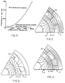
- Figs. 2-4 illustrate the above described phenomenon for a six-pole motor.
- the Figs. illustrate one-sixth of the motor rotor and stator assemblies.
- stator 14 is supplying flux to rotor 12, while the rotor is cooled to below the critical temperature.
- the coil space of stator windings 24 is, for example, twenty percent (20%) comprised of an HTSC material. If the winding is, for example, operating at a current density of 100,000 amperes/cm2 in a 2.0 Tesla field, a rotor surface flux density is produced having a peak field of 1.0 Tesla.
- Fig. 1 illustrates the above described phenomenon for a six-pole motor.
- the Figs. illustrate one-sixth of the motor rotor and stator assemblies.
- stator 14 is supplying flux to rotor 12
- the coil space of stator windings 24 is, for example, twenty percent (20%) comprised of an HTSC material. If the winding is, for example, operating at a
- the peak flux density in air gap A is, for example, 2.4 Tesla.
- the torque produced is 2439 newton-meters. If the motor were operated at, for example, 1800 rpm, it could theoretically produce 616 hp. As a practical matter, design limitations would probably limit the actual motor hp output to a maximum of approximately 100hp. It will be understood that the torque of motor 10 varies.
- a standard induction motor of comparable size and operating in a fan cooled enclosure produces approximately 15 hp when operating at 1775 rpm.
- Such a motor has a service factor of 1.25, and a maximum continuous hp rating of 18.75 hp.
- a brushless rare earth permanent magnet motor using samarium cobalt or neodymium-iron-boron magnets in a similar size package can produce 180 newton-meters of torque at 1800 rpm. Such a motor will produce approximately 45 hp.
- Fig. 5 a graph of horsepower versus density is presented for motor 10, a conventional induction motor, and a rare earth permanent magnet brushless D.C. motor. As is seen therein, at low current densities, the power output of motor 10 is low. However, as current density increases, the horsepower output of the motor increases rapidly.
- a second embodiment of the present invention comprises an axial gap motor 30 which includes a rotor assembly 32 and a stator assembly 34.
- the motor is shown installed in a single cryostat 36.
- the rotor and stator assemblies are either kept in separate cryostats, or the single cryostat is filled with a liquid Helium in such a way as to produce the same effect as if the assemblies were in separate cryostats.
- a cryostat temperature control (not shown) controls the temperature within the cryostat.
- stator assembly 34 comprises a mounting plate 38 of an appropriate material which is sized to fit within the cryostat.
- a stator 40 comprising a plurality of teeth 42, with associated stator windings 44a, 44b is mounted on the upperside of plate 38, as viewed in the drawings. It will be understood that the number of stator windings can vary.
- the stator teeth are formed, for example, of a steel material; while, again, the stator windings may be of a conventional electrical conducting material such as copper, or of a HTSC material.
- Projecting upwardly from the center of plate 38 is a cylindrical support 46 for supporting a shaft 48 of rotor assembly 32.
- the rotor assembly comprises a circular mounting plate 50 affixed on shaft 48 so when the end of the shaft is installed in support 46, the rotor assembly is in an axial, spaced relationship with respect to the stator assembly. As seen in Fig. 6, an air gap A' is thus created between the two assemblies.
- a plurality (8) of posts 52 which are of a metallic material, preferably steel.
- the posts are equidistantly spaced about the circumference of plate 50, the spacing between the posts being a function of the number of poles mounted on plate 50.
- the posts are positioned so they are aligned with the stator.
- the height of the posts is equal.
- Fitted adjacent the distal end of each post is a ring 54 of HTSC material.
- the ring is not of an HTSC material; but rather, a disk 56 of HTSC material is attached to the free end of the post. In either event, the purpose of the ring or disk is to trap magnetic fields.
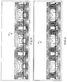
- Figs. 8 and 9 illustrate unwrapped side views of the rotor assembly shown in Figs. 6 and 7.
- Fig. 8 illustrates the condition in which the rotor assembly 12 temperature is above the critical temperature and current flowing through the stator windings impresses a field on the rotor.
- the temperature of rotor assembly is below the critical temperature Tc.
- the stator windings are not energized.
- flux trapping method described above flux is trapped in the rotor assembly. This trapped flux produces, for example, a current density of aproximately 5,000 amperes/cm2, and a 0.7 Tesla field.
- motor 30 operation of motor 30 is the same as that of motor 10.
- the sequence of lowering the temperatures in the respective cryostats is the same as described with respect to motor 10.
- the same effect is obtained by first filling the cryostat with a liquid cooling medium until the stator assembly is covered. The stator temperature falls below the critical temperature and the stator windings are then energized. At this time, the rotor temperature remains above the critical temperature. Now, more liquid coolant is added to the cryostat until the rotor assembly is also covered. This cause the rotor temperature to fall below the critical level.
- stator and rotor assembly temperatures follow the profile shown in Fig. 10, and operation of the motor is as described with respect to motor 10. That is, the stator windings are energized prior to the rotor assembly temperature falling below the critical temperature. Afterwards, the stator windings are de-energized and flux trapping occurs for the rotor to act as a permanent magnet so long as the rotor temperature is maintained below the critical level.
Landscapes
- Engineering & Computer Science (AREA)
- Power Engineering (AREA)
- Manufacturing & Machinery (AREA)
- Chemical & Material Sciences (AREA)
- Combustion & Propulsion (AREA)
- Superconductive Dynamoelectric Machines (AREA)
- Motor Or Generator Cooling System (AREA)
- Windings For Motors And Generators (AREA)
- Dc Machiner (AREA)
Applications Claiming Priority (2)
| Application Number | Priority Date | Filing Date | Title |
|---|---|---|---|
| US682447 | 1991-04-08 | ||
| US07/682,447 US5177054A (en) | 1991-04-08 | 1991-04-08 | Flux trapped superconductor motor and method therefor |
Publications (2)
| Publication Number | Publication Date |
|---|---|
| EP0508936A1 true EP0508936A1 (de) | 1992-10-14 |
| EP0508936B1 EP0508936B1 (de) | 1996-09-25 |
Family
ID=24739747
Family Applications (1)
| Application Number | Title | Priority Date | Filing Date |
|---|---|---|---|
| EP92630038A Expired - Lifetime EP0508936B1 (de) | 1991-04-08 | 1992-04-02 | Supraleitender Motor mit festgehaltenem Fluss und Verfahren dazu |
Country Status (7)
| Country | Link |
|---|---|
| US (1) | US5177054A (de) |
| EP (1) | EP0508936B1 (de) |
| JP (1) | JPH05276734A (de) |
| KR (1) | KR920020824A (de) |
| CA (1) | CA2059467C (de) |
| DE (1) | DE69213990T2 (de) |
| MX (1) | MX9201576A (de) |
Cited By (9)
| Publication number | Priority date | Publication date | Assignee | Title |
|---|---|---|---|---|
| EP1583209A4 (de) * | 2003-01-09 | 2009-11-11 | Univ Fukui | Supraleiter-magnetisierungseinrichtung undsupraleiter-synchronisationseinrichtung |
| WO2013014100A3 (de) * | 2011-07-25 | 2014-10-09 | Siemens Aktiengesellschaft | Elektrische maschine |
| US9577503B2 (en) | 2010-05-03 | 2017-02-21 | The Board Of Regents Of The University Of Texas System | Rotating machines using trapped field magnets and related methods |
| EP3627674A1 (de) * | 2018-09-18 | 2020-03-25 | Rolls-Royce plc | Elektrische maschine |
| EP3758215A1 (de) * | 2019-06-27 | 2020-12-30 | The Boeing Company | Hybridmotor mit gewickeltem läufer und generator mit induktionsspeisung und dauerstrom |
| US11056963B2 (en) | 2019-06-27 | 2021-07-06 | The Boeing Company | Hybrid wound-rotor motor and generator with induction feed and persistent current |
| US11069463B2 (en) | 2019-06-27 | 2021-07-20 | The Boeing Company | Hybrid wound-rotor motor and generator with induction feed and persistent current |
| WO2024110756A1 (en) * | 2022-11-24 | 2024-05-30 | Gkn Aerospace Services Limited | Electric motor having cryocooled armature litz windings |
| US12374981B2 (en) | 2023-03-30 | 2025-07-29 | The Boeing Company | Superconductor joining and joints |
Families Citing this family (39)
| Publication number | Priority date | Publication date | Assignee | Title |
|---|---|---|---|---|
| US5191618A (en) * | 1990-12-20 | 1993-03-02 | Hisey Bradner L | Rotary low-frequency sound reproducing apparatus and method |
| US5325002A (en) * | 1992-02-18 | 1994-06-28 | Electric Power Research Institute | Trapped-field, superconducting, induction-synchronous motor/generator having improved startup torque |
| US5256924A (en) * | 1992-08-10 | 1993-10-26 | Allied-Signal Inc. | Superconducting commutator for DC machines |
| US5581135A (en) * | 1993-09-15 | 1996-12-03 | Imra Material R & D Co., Ltd. | Superconducting motor |
| US5397953A (en) * | 1993-11-17 | 1995-03-14 | The United States Of America As Represented By The Secretary Of The Navy | Stator for disc type electric motor |
| US5841211A (en) * | 1994-07-15 | 1998-11-24 | Boyes; Thomas G. | Superconducting generator and system therefor |
| US5818097A (en) * | 1995-01-05 | 1998-10-06 | Superconductor Technologies, Inc. | Temperature controlling cryogenic package system |
| US6169354B1 (en) | 1996-05-24 | 2001-01-02 | Halo Data Devices, Inc. | Thin film electric motors |
| US5857342A (en) * | 1998-02-10 | 1999-01-12 | Superconductor Technologies, Inc. | Temperature controlling cryogenic package system |
| US6416215B1 (en) * | 1999-12-14 | 2002-07-09 | University Of Kentucky Research Foundation | Pumping or mixing system using a levitating magnetic element |
| US6204588B1 (en) | 1999-05-27 | 2001-03-20 | Halo Data Devices, Inc. | Rotor capable of being used as a recording media |
| US6758593B1 (en) | 2000-10-09 | 2004-07-06 | Levtech, Inc. | Pumping or mixing system using a levitating magnetic element, related system components, and related methods |
| US6392370B1 (en) | 2000-01-13 | 2002-05-21 | Bedini Technology, Inc. | Device and method of a back EMF permanent electromagnetic motor generator |
| US6768244B2 (en) * | 2000-04-25 | 2004-07-27 | General Electric Canada Inc. | Stator, dynamoelectric machine, and methods for fabricating same |
| US6608417B1 (en) * | 2000-09-05 | 2003-08-19 | Global Trading & Technology, Inc. | Super conductive bearing |
| RU2180156C1 (ru) * | 2001-03-30 | 2002-02-27 | Московский государственный авиационный институт (технический университет) | Сверхпроводниковая синхронная машина |
| ITMI20010978A1 (it) * | 2001-05-11 | 2002-11-11 | Edison Spa | Metodo per la preparazione di corpi massivi superconduttori di mgb2 altamente densificati relativi manufatti solidi e loro uso |
| US6711422B2 (en) * | 2001-09-17 | 2004-03-23 | Osman K. Mawardi | Thin film superconducting synchronous motor |
| DE10158757A1 (de) * | 2001-11-29 | 2003-06-18 | Siemens Ag | Schiffsantrieb |
| DE10158805A1 (de) * | 2001-11-30 | 2003-06-18 | Siemens Ag | Schiffsantrieb |
| US6707221B2 (en) * | 2002-04-08 | 2004-03-16 | General Electric Company | Axial flux machine, stator and fabrication method |
| JP2006204085A (ja) * | 2004-12-24 | 2006-08-03 | Sumitomo Electric Ind Ltd | アキシャルギャップ型超電導モータ |
| JP4706351B2 (ja) * | 2005-06-20 | 2011-06-22 | 住友電気工業株式会社 | 誘導子型モータ |
| WO2008141245A2 (en) * | 2007-05-09 | 2008-11-20 | Motor Excellence, Llc | Electrical output generating devices and driven electrical devices having tape wound core laminate rotor or stator elements, and methods of making and use thereof |
| US7868511B2 (en) * | 2007-05-09 | 2011-01-11 | Motor Excellence, Llc | Electrical devices using disk and non-disk shaped rotors |
| US7923886B2 (en) | 2008-11-03 | 2011-04-12 | Motor Excellence, Llc | Transverse and/or commutated flux system rotor concepts |
| DK2548289T3 (da) * | 2010-03-15 | 2020-02-17 | Motor Excellence Llc | Tværgående og/eller kommuterede strømningssystemer med faseforskydning |
| WO2011115632A1 (en) | 2010-03-15 | 2011-09-22 | Motor Excellence Llc | Transverse and/or commutated flux systems configured to provide reduced flux leakage, hysteresis loss reduction, and phase matching |
| CN102986115A (zh) * | 2010-03-15 | 2013-03-20 | 电扭矩机器股份有限公司 | 用于电动自行车的横向和/或换向通量系统 |
| EP2641316B1 (de) | 2010-11-17 | 2019-02-13 | Motor Excellence, LLC | Quer- oder mischflusssysteme mit segmentierten statorlamellen |
| WO2012067896A2 (en) | 2010-11-17 | 2012-05-24 | Motor Excellence, Llc | Transverse and/or commutated flux systems having laminated and powdered metal portions |
| WO2012067895A2 (en) | 2010-11-17 | 2012-05-24 | Motor Excellence, Llc | Transverse and/or commutated flux system coil concepts |
| US20150133303A1 (en) * | 2012-12-31 | 2015-05-14 | TransLife Energy Solutions, Inc. | Electrical Generator |
| AU2014360790A1 (en) * | 2013-09-26 | 2016-05-12 | Dominion Alternative Energy, Llc | Superconductive electric motor and generator |
| JP6566483B2 (ja) * | 2014-03-28 | 2019-08-28 | 国立大学法人東京海洋大学 | ラジアルギャップ型超電導同期機、着磁装置、及び着磁方法 |
| EP3573619A4 (de) | 2017-01-27 | 2020-10-28 | SignalRX Pharmaceuticals, Inc. | Thienopyranone und furanopyranone als kinase-, bromodomänen- und checkpoint-inhibitoren |
| CN107294353A (zh) * | 2017-07-18 | 2017-10-24 | 四川大学 | 一种永磁式超导磁体无线充能电源 |
| DE102018216896A1 (de) * | 2018-10-02 | 2020-04-02 | Siemens Aktiengesellschaft | Rotor und Maschine mit supraleitendem Permanentmagneten für hohe magnetische Flussdichten |
| JP6899022B1 (ja) * | 2020-04-27 | 2021-07-07 | 大倉 健吾 | モータ装置 |
Citations (5)
| Publication number | Priority date | Publication date | Assignee | Title |
|---|---|---|---|---|
| US3005117A (en) * | 1959-03-20 | 1961-10-17 | Gen Electric | Electro-mechanical device |
| US3242418A (en) * | 1962-08-31 | 1966-03-22 | Dynatech Corp | Low temperature electromechanical transducer |
| US3427482A (en) * | 1965-03-24 | 1969-02-11 | Siemens Ag | Apparatus for generating an electric current in a superconductive coil |
| EP0261635A1 (de) * | 1986-09-25 | 1988-03-30 | Gec Alsthom Sa | Supraleitende elektrische Drehmaschine und ihre thermische Isolierung |
| WO1991003860A1 (en) * | 1989-09-01 | 1991-03-21 | Allied-Signal Inc. | Dynamoelectric machine with superconducting magnet rotor |
Family Cites Families (10)
| Publication number | Priority date | Publication date | Assignee | Title |
|---|---|---|---|---|
| US490280A (en) * | 1893-01-24 | hansen | ||
| DE1488065B2 (de) * | 1964-12-18 | 1972-05-04 | Siemens AG, 1000 Berlin u. 8000 München | Gleichstrommaschine in gleichpolbauart mit supraleitender ankerwicklung |
| US3405290A (en) * | 1965-07-21 | 1968-10-08 | Halas Edward | Superconducting generator |
| US3564307A (en) * | 1968-07-24 | 1971-02-16 | Hitachi Ltd | Rotary electric ac generator utilizing the magnetic shielding and trapping by superconducting plates |
| US3584246A (en) * | 1968-12-20 | 1971-06-08 | Edward Halas | Magnetic field producing means |
| US3609418A (en) * | 1969-09-30 | 1971-09-28 | Edward Halas | Mechanical power transmission systems |
| JPS5142285B1 (de) * | 1969-10-09 | 1976-11-15 | ||
| US3762042A (en) * | 1971-06-17 | 1973-10-02 | Tokai Cold Forming Co Ltd | Method of manufacturing a core segment for a disc type induction motor rotor |
| JPS6417648A (en) * | 1987-07-08 | 1989-01-20 | Ii Andaason Jiyatsuku | Speed variable propelling wheelchair |
| US4870838A (en) * | 1988-03-21 | 1989-10-03 | Zeamer Geoffrey H | Cryostat |
-
1991
- 1991-04-08 US US07/682,447 patent/US5177054A/en not_active Expired - Fee Related
-
1992
- 1992-01-16 CA CA002059467A patent/CA2059467C/en not_active Expired - Fee Related
- 1992-04-02 DE DE69213990T patent/DE69213990T2/de not_active Expired - Fee Related
- 1992-04-02 EP EP92630038A patent/EP0508936B1/de not_active Expired - Lifetime
- 1992-04-06 MX MX9201576A patent/MX9201576A/es not_active IP Right Cessation
- 1992-04-07 KR KR1019920005741A patent/KR920020824A/ko not_active Withdrawn
- 1992-04-08 JP JP4115543A patent/JPH05276734A/ja active Pending
Patent Citations (5)
| Publication number | Priority date | Publication date | Assignee | Title |
|---|---|---|---|---|
| US3005117A (en) * | 1959-03-20 | 1961-10-17 | Gen Electric | Electro-mechanical device |
| US3242418A (en) * | 1962-08-31 | 1966-03-22 | Dynatech Corp | Low temperature electromechanical transducer |
| US3427482A (en) * | 1965-03-24 | 1969-02-11 | Siemens Ag | Apparatus for generating an electric current in a superconductive coil |
| EP0261635A1 (de) * | 1986-09-25 | 1988-03-30 | Gec Alsthom Sa | Supraleitende elektrische Drehmaschine und ihre thermische Isolierung |
| WO1991003860A1 (en) * | 1989-09-01 | 1991-03-21 | Allied-Signal Inc. | Dynamoelectric machine with superconducting magnet rotor |
Cited By (13)
| Publication number | Priority date | Publication date | Assignee | Title |
|---|---|---|---|---|
| EP1583209A4 (de) * | 2003-01-09 | 2009-11-11 | Univ Fukui | Supraleiter-magnetisierungseinrichtung undsupraleiter-synchronisationseinrichtung |
| US9577503B2 (en) | 2010-05-03 | 2017-02-21 | The Board Of Regents Of The University Of Texas System | Rotating machines using trapped field magnets and related methods |
| WO2013014100A3 (de) * | 2011-07-25 | 2014-10-09 | Siemens Aktiengesellschaft | Elektrische maschine |
| US9306441B2 (en) | 2011-07-25 | 2016-04-05 | Siemens Aktiengesellschaft | Electric machine |
| RU2611067C2 (ru) * | 2011-07-25 | 2017-02-21 | Сименс Акциенгезелльшафт | Электрическая машина |
| US11152844B2 (en) | 2018-09-18 | 2021-10-19 | Rolls-Royce Plc | Electric machine |
| EP3627674A1 (de) * | 2018-09-18 | 2020-03-25 | Rolls-Royce plc | Elektrische maschine |
| EP3982524A1 (de) * | 2018-09-18 | 2022-04-13 | Rolls-Royce plc | Elektrische maschine |
| EP3758215A1 (de) * | 2019-06-27 | 2020-12-30 | The Boeing Company | Hybridmotor mit gewickeltem läufer und generator mit induktionsspeisung und dauerstrom |
| US11056963B2 (en) | 2019-06-27 | 2021-07-06 | The Boeing Company | Hybrid wound-rotor motor and generator with induction feed and persistent current |
| US11069463B2 (en) | 2019-06-27 | 2021-07-20 | The Boeing Company | Hybrid wound-rotor motor and generator with induction feed and persistent current |
| WO2024110756A1 (en) * | 2022-11-24 | 2024-05-30 | Gkn Aerospace Services Limited | Electric motor having cryocooled armature litz windings |
| US12374981B2 (en) | 2023-03-30 | 2025-07-29 | The Boeing Company | Superconductor joining and joints |
Also Published As
| Publication number | Publication date |
|---|---|
| DE69213990T2 (de) | 1997-02-06 |
| CA2059467A1 (en) | 1992-10-09 |
| JPH05276734A (ja) | 1993-10-22 |
| MX9201576A (es) | 1993-08-01 |
| CA2059467C (en) | 1997-03-04 |
| KR920020824A (ko) | 1992-11-21 |
| DE69213990D1 (de) | 1996-10-31 |
| EP0508936B1 (de) | 1996-09-25 |
| US5177054A (en) | 1993-01-05 |
Similar Documents
| Publication | Publication Date | Title |
|---|---|---|
| US5177054A (en) | Flux trapped superconductor motor and method therefor | |
| US4679313A (en) | Method of making a servo motor with high energy product magnets | |
| US4176291A (en) | Stored field superconducting electrical machine and method | |
| US4954739A (en) | Servo motor with high energy product magnets | |
| US4908347A (en) | Dynamoelectric machine with diamagnetic flux shield | |
| US7453174B1 (en) | Superconducting electric motor | |
| US6603231B2 (en) | Hybrid superconducting motor/generator | |
| CN102610360B (zh) | 用于磁化稀土永磁体的系统和方法 | |
| WO1999009638A1 (en) | Compact hybrid electrical machine | |
| EP0580854A1 (de) | Supraleitender synchroner induktionsmotor/-generator mit eingefangenem feld und verbessertem anlaufmoment | |
| WO2000046905A1 (en) | High efficiency electro-mechanical energy conversion device | |
| US4987674A (en) | Method of making a dynamoelectric machine with superconducting magnet rotor | |
| US4843268A (en) | Asymmetric field electromagnetic motor | |
| US5138207A (en) | Flux trapped superconductor sychronous motor with creep compensation | |
| US5144179A (en) | Superconducting brushless homopolar motor with multiple winding rotor | |
| US7291958B2 (en) | Rotating back iron for synchronous motors/generators | |
| US6359365B1 (en) | Superconducting synchronous machine field winding protection | |
| Hirakawa et al. | Developments of superconducting motor with YBCO bulk magnets | |
| US6791229B2 (en) | Thin film superconducting motor with magnetically-quenched rotor | |
| Tixador et al. | 150-kW experimental superconducting permanent-magnet motor | |
| US9231444B2 (en) | Superconductor winding | |
| JP3365534B2 (ja) | 磁石同期回転機の永久磁石付回転子 | |
| EP4672575A1 (de) | Bürstenloser synchronmotor mit axialem fluss, kryogene anlage mit dem motor und zugehöriges betriebsverfahren der anlage | |
| GLEBOV et al. | DEVELOPMENT OF SUPERCONDUCTING GENERATORS AND MOTORS IN THE USSR |
Legal Events
| Date | Code | Title | Description |
|---|---|---|---|
| PUAI | Public reference made under article 153(3) epc to a published international application that has entered the european phase |
Free format text: ORIGINAL CODE: 0009012 |
|
| AK | Designated contracting states |
Kind code of ref document: A1 Designated state(s): DE FR GB IT |
|
| 17P | Request for examination filed |
Effective date: 19921212 |
|
| 17Q | First examination report despatched |
Effective date: 19940711 |
|
| GRAG | Despatch of communication of intention to grant |
Free format text: ORIGINAL CODE: EPIDOS AGRA |
|
| GRAH | Despatch of communication of intention to grant a patent |
Free format text: ORIGINAL CODE: EPIDOS IGRA |
|
| GRAH | Despatch of communication of intention to grant a patent |
Free format text: ORIGINAL CODE: EPIDOS IGRA |
|
| GRAA | (expected) grant |
Free format text: ORIGINAL CODE: 0009210 |
|
| AK | Designated contracting states |
Kind code of ref document: B1 Designated state(s): DE FR GB IT |
|
| ET | Fr: translation filed | ||
| REF | Corresponds to: |
Ref document number: 69213990 Country of ref document: DE Date of ref document: 19961031 |
|
| ITF | It: translation for a ep patent filed | ||
| PGFP | Annual fee paid to national office [announced via postgrant information from national office to epo] |
Ref country code: FR Payment date: 19970307 Year of fee payment: 6 |
|
| PGFP | Annual fee paid to national office [announced via postgrant information from national office to epo] |
Ref country code: GB Payment date: 19970319 Year of fee payment: 6 |
|
| PGFP | Annual fee paid to national office [announced via postgrant information from national office to epo] |
Ref country code: DE Payment date: 19970321 Year of fee payment: 6 |
|
| PLBE | No opposition filed within time limit |
Free format text: ORIGINAL CODE: 0009261 |
|
| 26N | No opposition filed | ||
| PG25 | Lapsed in a contracting state [announced via postgrant information from national office to epo] |
Ref country code: GB Free format text: LAPSE BECAUSE OF NON-PAYMENT OF DUE FEES Effective date: 19980402 |
|
| PG25 | Lapsed in a contracting state [announced via postgrant information from national office to epo] |
Ref country code: FR Free format text: THE PATENT HAS BEEN ANNULLED BY A DECISION OF A NATIONAL AUTHORITY Effective date: 19980430 |
|
| GBPC | Gb: european patent ceased through non-payment of renewal fee |
Effective date: 19980402 |
|
| PG25 | Lapsed in a contracting state [announced via postgrant information from national office to epo] |
Ref country code: DE Free format text: LAPSE BECAUSE OF NON-PAYMENT OF DUE FEES Effective date: 19990202 |
|
| REG | Reference to a national code |
Ref country code: FR Ref legal event code: ST |
|
| PG25 | Lapsed in a contracting state [announced via postgrant information from national office to epo] |
Ref country code: IT Free format text: LAPSE BECAUSE OF NON-PAYMENT OF DUE FEES;WARNING: LAPSES OF ITALIAN PATENTS WITH EFFECTIVE DATE BEFORE 2007 MAY HAVE OCCURRED AT ANY TIME BEFORE 2007. THE CORRECT EFFECTIVE DATE MAY BE DIFFERENT FROM THE ONE RECORDED. Effective date: 20050402 |