EP0508739A2 - Einrichtung zum Erfassen der Änderung im Innendruck eines Zylinders - Google Patents
Einrichtung zum Erfassen der Änderung im Innendruck eines Zylinders Download PDFInfo
- Publication number
- EP0508739A2 EP0508739A2 EP92303098A EP92303098A EP0508739A2 EP 0508739 A2 EP0508739 A2 EP 0508739A2 EP 92303098 A EP92303098 A EP 92303098A EP 92303098 A EP92303098 A EP 92303098A EP 0508739 A2 EP0508739 A2 EP 0508739A2
- Authority
- EP
- European Patent Office
- Prior art keywords
- plug
- insertion hole
- sensor
- annular
- shell
- Prior art date
- Legal status (The legal status is an assumption and is not a legal conclusion. Google has not performed a legal analysis and makes no representation as to the accuracy of the status listed.)
- Granted
Links
- 238000003780 insertion Methods 0.000 claims abstract description 75
- 230000037431 insertion Effects 0.000 claims abstract description 74
- 230000002093 peripheral effect Effects 0.000 claims description 29
- WABPQHHGFIMREM-UHFFFAOYSA-N lead(0) Chemical compound [Pb] WABPQHHGFIMREM-UHFFFAOYSA-N 0.000 claims description 11
- 238000005452 bending Methods 0.000 claims description 9
- 238000000034 method Methods 0.000 claims description 9
- 239000002131 composite material Substances 0.000 claims description 8
- 238000004519 manufacturing process Methods 0.000 claims description 6
- 239000007788 liquid Substances 0.000 claims description 5
- 239000011342 resin composition Substances 0.000 claims description 3
- 239000000203 mixture Substances 0.000 claims description 2
- 229920005989 resin Polymers 0.000 description 7
- 239000011347 resin Substances 0.000 description 7
- 229910052751 metal Inorganic materials 0.000 description 4
- 239000002184 metal Substances 0.000 description 4
- 230000006835 compression Effects 0.000 description 2
- 238000007906 compression Methods 0.000 description 2
- 238000010276 construction Methods 0.000 description 2
- 230000005484 gravity Effects 0.000 description 2
- 238000010008 shearing Methods 0.000 description 2
- RYGMFSIKBFXOCR-UHFFFAOYSA-N Copper Chemical compound [Cu] RYGMFSIKBFXOCR-UHFFFAOYSA-N 0.000 description 1
- 239000000853 adhesive Substances 0.000 description 1
- 230000001070 adhesive effect Effects 0.000 description 1
- 229910052782 aluminium Inorganic materials 0.000 description 1
- XAGFODPZIPBFFR-UHFFFAOYSA-N aluminium Chemical compound [Al] XAGFODPZIPBFFR-UHFFFAOYSA-N 0.000 description 1
- PNEYBMLMFCGWSK-UHFFFAOYSA-N aluminium oxide Inorganic materials [O-2].[O-2].[O-2].[Al+3].[Al+3] PNEYBMLMFCGWSK-UHFFFAOYSA-N 0.000 description 1
- 238000002485 combustion reaction Methods 0.000 description 1
- 238000004891 communication Methods 0.000 description 1
- 229910052802 copper Inorganic materials 0.000 description 1
- 239000010949 copper Substances 0.000 description 1
- 238000001514 detection method Methods 0.000 description 1
- 238000010292 electrical insulation Methods 0.000 description 1
- 239000012777 electrically insulating material Substances 0.000 description 1
- 239000003822 epoxy resin Substances 0.000 description 1
- 239000012530 fluid Substances 0.000 description 1
- 239000000446 fuel Substances 0.000 description 1
- 238000002347 injection Methods 0.000 description 1
- 239000007924 injection Substances 0.000 description 1
- 238000009413 insulation Methods 0.000 description 1
- 229920000647 polyepoxide Polymers 0.000 description 1
- 238000003825 pressing Methods 0.000 description 1
- 229910000679 solder Inorganic materials 0.000 description 1
- 238000005476 soldering Methods 0.000 description 1
- 229910001220 stainless steel Inorganic materials 0.000 description 1
- 239000010935 stainless steel Substances 0.000 description 1
Images


Classifications
-
- G—PHYSICS
- G01—MEASURING; TESTING
- G01L—MEASURING FORCE, STRESS, TORQUE, WORK, MECHANICAL POWER, MECHANICAL EFFICIENCY, OR FLUID PRESSURE
- G01L23/00—Devices or apparatus for measuring or indicating or recording rapid changes, such as oscillations, in the pressure of steam, gas, or liquid; Indicators for determining work or energy of steam, internal-combustion, or other fluid-pressure engines from the condition of the working fluid
- G01L23/08—Devices or apparatus for measuring or indicating or recording rapid changes, such as oscillations, in the pressure of steam, gas, or liquid; Indicators for determining work or energy of steam, internal-combustion, or other fluid-pressure engines from the condition of the working fluid operated electrically
- G01L23/10—Devices or apparatus for measuring or indicating or recording rapid changes, such as oscillations, in the pressure of steam, gas, or liquid; Indicators for determining work or energy of steam, internal-combustion, or other fluid-pressure engines from the condition of the working fluid operated electrically by pressure-sensitive members of the piezoelectric type
-
- G—PHYSICS
- G01—MEASURING; TESTING
- G01L—MEASURING FORCE, STRESS, TORQUE, WORK, MECHANICAL POWER, MECHANICAL EFFICIENCY, OR FLUID PRESSURE
- G01L23/00—Devices or apparatus for measuring or indicating or recording rapid changes, such as oscillations, in the pressure of steam, gas, or liquid; Indicators for determining work or energy of steam, internal-combustion, or other fluid-pressure engines from the condition of the working fluid
- G01L23/22—Devices or apparatus for measuring or indicating or recording rapid changes, such as oscillations, in the pressure of steam, gas, or liquid; Indicators for determining work or energy of steam, internal-combustion, or other fluid-pressure engines from the condition of the working fluid for detecting or indicating knocks in internal-combustion engines; Units comprising pressure-sensitive members combined with ignitors for firing internal-combustion engines
Definitions
- This invention relates generally to a device for detecting a change in internal pressure of a cylinder and, more specifically, to a mounting structure of a piezoelectric sensor mounted to a cylinder head of an internal combustion engine to detect a change in pressure within the cylinder caused by knocking or fuel injection.
- the present invention is also directed to a method of the manufacture of a piezoelectric sensor.
- Figs. 25 and 26 One known internal pressure detecting device is illustrated in Figs. 25 and 26.
- Designated as S is an annular piezoelectric sensor composed of a metal shell surrounding a laminate including an annular piezoelectric element and upper and lower cushioning rings.
- the sensor S is fixed on a plug seat r 2 by tightening with an ignition plug T so that the pressure change within the cylinder is transmitted to the sensor S as a mechanical strain to cause the sensor S to output a corresponding electrical.
- the cylinder head P is provided with a plug insertion hole r 1 having the plug seat r 2 and an internally threaded portion r 3 .
- the ignition plug T has a stepped portion t 2 engageable with the plug seat r 2 and an externally threaded tip end portion threadingly engageable with the internally threaded portion r 3 , so that when the plug T is screwed in the plug hole r 1 , the sensor S disposed on the plug seat r 2 , optionally through a gasket, is tightly fixed thereon.
- the shell 4 of the sensor S is composed of an outer ring plate 5a, an inner ring plate 5b and an annular bottom plate 5c by which an annular space 6 is defined. Disposed in the space 6 are a pair of annular piezoelectric elements 1 and 1, an annular electrode plate 2 interposed between the piezoelectric elements 1 and 1, and a top cushioning ring 3.
- the electrode ring 2 has a portion 2a which extends radially outwardly through the outer ring plate 5a and to which a lead wire 7 is electrically connected to send an electrical signal from the sensor S to a suitable signal detecting device (not shown).
- the sensor S is pressed between the plug seat r 2 of the plug insertion hole r 1 and the stepped portion t 2 of the plug T.
- the tightening torque of the plug T is acted on the sensor S directly or indirectly through a gasket. Since such a torque includes both axial compression stress and tortional or twisting stress, the sensor S which has relatively low shearing strength tends to be broken or damaged and is deteriorated in the piezoelectric characteristics thereof.
- a stopper is disposed for preventing the rotation of the sensor S at the time of the mounting on the cylinder head P.
- the use of such a stopper is disadvantageous from the standpoint of economy and productivity because the mounting structure becomes unavoidably complicated. Further, the use of a stopper results in the increase in distance between the top surface of the sensor S and the plug seat r 2 so that it becomes difficult to locate the tip end of the plug P, at which spark discharge takes place, at an appropriate position.
- Another object of the present invention is to provide a device of the above-mentioned type which does not use a specific stopper and which can prevent a twisting stress from acting on the piezoelectric sensor during the mounting thereof on the cylinder head.
- a device for detecting a change in internal pressure of a cylinder which comprises: a cylinder head; an axially extending ignition plug including a large diameter periphery portion, a small diameter periphery portion extending coaxially from an edge of the large diameter portion to form an annular stepped portion on the edge, and an externally threaded tip end portion coaxially extending from the small diameter periphery portion; a plug insertion hole formed in the cylinder head for receiving part of the ignition plug and having an internally threaded portion adapted to be in threading engagement with the externally threaded tip end portion of the ignition plug and a plug seat engageable with the annular stepped portion of the ignition plug; and an annular piezoelectric sensor disposed on the plug seat and having an opening whose diameter is greater than that of the small diameter periphery portion of the ignition plug but smaller than the large diameter periphery portion thereof, so that the ignition plug is capable of being
- the present invention provides a device for detecting a change in internal pressure of a cylinder, which comprises: a cylinder head; an axially extending ignition plug including a large diameter periphery portion, a small diameter periphery portion extending coaxially from an edge of the large diameter portion to form an annular stepped portion on the edge, and an externally threaded tip end portion coaxially extending from the small diameter periphery portion; a plug insertion hole formed in the cylinder head for receiving part of the ignition plug and having an internally threaded portion adapted to be in threading engagement with the externally threaded tip end portion of the ignition plug and a plug seat engageable with the annular stepped portion of the ignition plug, the plug insertion hole having a circular inside peripheral portion whose center is deviated from the axis of the internally threaded portion of the plug hole; an annular piezoelectric sensor disposed on the plug seat and having an opening whose diameter is greater than that of the small diameter periphery portion of the ignition plug
- the present invention also provides a method of the production of a piezoelectric sensor, which comprises the steps of: providing a shell in the form of a ring having an annular top plate and a pair of outer and inner tubular plates extending from the outer and inner peripheral edges of the top plate, respectively, in the direction perpendicular to the top plate, the outer and inner edges of the top plate being circular in shape with the center of the outer edge being deviated from that of the inner edge; providing an annular composite body including an annular layer of a piezoelectric element; providing an annular bottom plate which matches the annular space defined between the outer and inner tubular plates; fitting the composite body and the bottom plate in this order in the space between the outer and inner tubular plates with the openings of the composite body and the bottom plate being inserted into the inner tubular plate; radially outwardly folding an end portion of the inner tubular plate to cover an inner periphery of the bottom plate; and then radially inwardly folding an end portion of the outer tubular plate to cover an outer peripher
- Figs. 1 and 2 depict a first embodiment of a cylinder internal pressure detecting device according to the present invention.
- the same reference numerals refer to similar component parts.
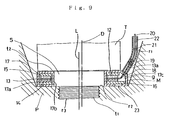
- designated as T is an axially extending ignition plug including a large diameter periphery portion, a small diameter periphery portion extending coaxially from an edge of the large diameter portion to form an annular stepped portion t 2 on the edge, and an externally threaded tip end portion coaxially extending from the small diameter periphery portion.
- the plug T is arranged to be attached to a plug insertion hole r 1 formed in a cylinder head P.
- the plug insertion hole r 1 has an internally threaded portion r 3 adapted to be in threading engagement with the externally threaded tip end portion of the ignition plug T and a plug seat r 2 engageable with the annular stepped portion t 2 of the ignition plug T.
- an annular piezoelectric sensor S Disposed on the plug seat r 2 is an annular piezoelectric sensor S having an opening whose diameter is greater than that of the small diameter periphery portion of the ignition plug T but smaller than the large diameter periphery portion thereof, so that when the ignition plug T is screwed into the plug insertion hole r 1 the piezoelectric sensor S is tightly pressed between the annular stepped portion t 2 of the ignition plug T and the plug seat r 2 of the plug insertion hole r 1 .
- the sensor S and the plug insertion hole r 1 are shaped so that when the ignition plug T is screwed for being fitted to the plug hole r 1 , part of the outer periphery of the sensor S placed on the plug seat r 2 is brought into engagement with an inside periphery of the plug hole r 1 and is thereby prevented from being further rotated in the screwing direction.
- the sensor S has such a portion M in the outer periphery 5a thereof that the distance between the portion M and the rotational axis L is greater than the shortest distance between the inside periphery of the insertion hole r 1 extending from the plug seat r 2 and the rotational axis L.
- the plug hole r 1 has a circular cross section and has a central axis D 2 which is deviated from the central axis D 1 of the internally threaded portion r 3 .
- the central axis D 1 serves as a rotational axis L of the ignition plug T.
- the sensor S has a circular outer ring plate 5a 1 whose center axis d 2 is deviated from the center axis d 1 of the inner ring plate 5b.
- the axes d 1 and d 2 coincide with the axes D 1 and D 2 , respectively.
- the diameter of the sensor S is smaller than that of the circular inside periphery r21 extending from the plug seat r 2 but is larger than the shortest distance between the rotation axis L and the inner periphery r21 so that the outer periphery 5a 1 of the sensor S has a portion M which is engageable with the inside peripheral portion r21 of the plug insertion hole r 1 upon rotation thereof about the axis L of the internally threaded portion r 3 of the plug insertion hole r 1 .
- the sensor S has a polygonal (hexagonal in the specific embodiment shown) outer periphery 5a 2 and the plug insertion hole r 1 has a polygonal (hexagonal in this embodiment) inside peripheral portion r22 extending the plug seat r 2 so that the outer periphery 5a 2 of the sensor S has a portion M which is engageable with the inside peripheral portion r22 of the plug insertion hole r 1 upon rotation thereof about the axis L of the internally threaded portion r 3 coaxially formed in the plug insertion hole r 1 .
- the sensor S has an ellipsoidal outer periphery 5a 3 and the plug insertion hole r 1 has an ellipsoidal inside peripheral portion r23 extending from the plug seat r 2 so that the outer periphery 5a 3 of the sensor S has a portion M which is engageable with the inside peripheral portion r23 of the plug insertion hole 1 upon rotation thereof about the axis L of the internally threaded portion r 3 of the plug insertion hole r 1 .
- the sensor S has a D-shaped outer periphery 5a 4 .
- the outer periphery of the sensor S is circular in shape with an arc portion being cut away therefrom.
- the plug insertion hole r 1 too has a D-shaped inside peripheral portion r24 so that the outer periphery 5a 4 of the sensor S has a portion M which is engageable with the inside peripheral portion r24 of the plug insertion hole r 1 upon rotation thereof about the axis L of the internally threaded portion r 3 of the plug insertion hole r 1 .
- the protruded portion is engageable with an inside peripheral portion r24 of the plug insertion hole r 1 upon rotation thereof about the axis L of the internally threaded portion r 3 of the plug insertion hole r 1 .
- the space between the metal shell 4 and the laminate including the piezoelectric elements 2 may be filled with a heat-resisting, electrically insulating material such as an epoxy resin composition, if desired.
- the senor S includes a ring-shaped shell 17 composed of a pair of parallel, top and bottom annular walls and a pair of outer and inner tubular walls 17a and 17b. Disposed within the shell 17 is a laminate 10 including an annular piezoelectric element 12, a ring electrode 13, an insulating ring plate 14 formed, for example, of alumina, an annular, top plate 15 formed of a metal such as aluminum or stainless steel, and an annular bottom plate 16 formed of a metal similar to the plate 15.
- the bottom wall of the shell 17 is formed by radially inwardly bending an end portion of the outer tubular wall and by radially outwardly bending an end portion of the inner tubular wall such that the laminate 10 is tightly held within the shell 17 with an abutting portion or aperture 23 being positioned in the bottom of the shell 17.
- the corner edges of the top and bottom plates 15 and 16 may be rounded so as to improve the close contact between the laminate 10 and the shell 17.
- the cylinder head P has a plug hole r 1 which has a circular cross section and whose central axis D is deviated from the central axis L of the internally threaded portion r 3 into which a plug T is to be threadingly fitted.
- the outer tubular wall 17a of the sensor S has a circular outer periphery whose center axis is deviated from the center axis of the inner tubular wall 17b.
- the central axes of the outer and inner walls 17a and 17b of the sensor S coincide with the axes D and L, respectively.
- the diameter of the outer tubular wall 17a of the sensor S is smaller than or equal to that of the circular inside periphery extending from the plug seat r 2 so that the outer periphery of the sensor S has a portion M which is engageable with the inside peripheral portion of the plug insertion hole r 1 upon rotation thereof about the axis L of the internally threaded portion r 3 of the plug insertion hole r 1 .
- the senor S has an annular shape whose radial width varies throughout.
- the bottom plate 16 is eccentric and extends throughout the inside bottom wall of the sensor S while the top plate 15 is concentric and has the same diameter as that of the laminate 10.
- a space g between the outer periphery of the laminate 10 and the outer tubular wall 17a of the shell.
- This space g is used to connect a lead wire 10 to the electrode plate 13.
- a portion of the edge defined by the top wall and the outer wall 17a of the shell 17 is tapered at a position adjacent to the space g to form a tapered surface 17c.
- the tapered surface 17c is provided with an opening 18 and with a guide pipe 19 fixed thereto, for example, by soldering.
- the guide pipe 19 is oriented in the direction normal to the tapered surface 17c which is oriented at an angle of 15° to 45° with respect to the top wall of the sensor S.
- the guide pipe 19 is bent and vertically extends in the end portion 22.
- the electrode ring 13 has an extended portion 13a extending through the space g, the opening 18 and the guide pipe 19 and is electrically connected to the lead wire 20 with a solder 21.
- the sensor S provided with the above wire leading structure is placed on the plug seat r 2 and is fixed there by screwing the plug T in the threaded portion r 3 .
- the guide pipe 19 is obliquely oriented, a sufficient space is available in the plug insertion hole r 1 to insert a tightening tool for the attachment of the plug T to the hole r 1 . Since the screwing of the plug T into the hole r 1 does not cause the sensor S to freely rotate, a shearing stress is not acted on the sensor S.
- the pressure within the cylinder is changed, this is transmitted to the sensor S through the plug T.
- the mechanical stress is thus transmitted to the piezoelectric element 12 through the upper and lower plates 15 and 16 so that an electrical signal corresponding to the mechanical stress is outputted from the sensor S and is fed through the electrode ring 13 and lead wire 20 to a suitable signal detector.
- the bottom wall of the sensor S is formed by bending end portions of the outer and inner tubular side walls.
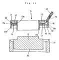
- Fig. 11 illustrates the fabrication of such a sensor S.
- the outer and inner ring plates 17a and 17b have extensions 17y and 17x, respectively. After the laminate 10 has been fitted into the shell 17, the extensions 17y and 17x are bent and pressed over the bottom plate 16. In this case, the length of the extension 17x is greater than that of the extension 17y and the extension 17x is bent prior to the extension 17y.
- the bent portion 17x can be tightly pressed against the bottom plate 16 because the space in the shell 17 is filled with the laminate 10.
- the laminate 10 can be held in a stable manner in the shell 17 by the bending of the extension 17x.
- the extension 17y is bent and pressed with the press member 31.
- the presence of the space g does not cause movement of the laminate 10 which has been already tightly secured in the shell 17.
- the bottom wall can be formed uniformly.
- an inner part 23a of the bottom wall formed by the extension 17x has a wider radial width than that of an outer part 23b formed by the extension 17y as shown in Fig. 12. This is advantage because the piezoelectric element 12 can be evenly supported by the inner part 23a so that the mechanical stress can be uniformly applied to the element 12, thereby ensuring satisfactory responsibility.
- bent portions 17x and 17y be present in the bottom of the sensor S, since the aperture 23 between the inner and outer parts 23a and 23b can be entirely faced to the plug seat r 2 and the entire bottom wall can be contacted with the plug seat r 2 , whereby the piezoelectric element 12 can uniformly receive the mechanical stress.
- Figs. 14 and 15 illustrate a suitable method for the fitting of the bottom plate 16.
- a shell 17 in the form of a ring having an annular plate and a pair of outer and inner tubular plates 17a and 17b extending from the outer and inner peripheral edges of the annular plate, respectively, in the direction perpendicular to the plate is provided.
- the outer and inner plates 17a and 17b are circular in cross section and the centers thereof are deviated from each other.
- the length of the inner plate 17a is greater than that of the outer plate 17b.
- the shell 17 constructed as above and bearing the laminate 10 is fitted to a vibrator 32 with the open end portion thereof being oriented upward.
- the vibrator 32 has a base portion 33 from which a circular guide 34 extends upward.
- the base portion 33 has a drive member 35 operable to cause the vibrator 32 to vibrate.
- the shell 17 is placed on the vibrator 32 with the guide 34 being inserted into the inner tubular plate 17b.
- an annular plate 16 which matches the annular space 17d defined between the outer and inner plates 17a and 17b is fitted on the guide 34.
- the drive means 35 is operated to vibrate the vibrator 32. This causes the annular plate 16 to rotate about the guide 34.
- the annular plate 16 is positioned so that the outer periphery thereof matches the shape of the annular space 17d of the shell, the plate 16 falls within the space 17d by gravity.
- the driving of the vibrator 32 may be effected by any other suitable means as long as the annular plate 16 placed on the shell 17 can be rotated about the guide 34.
- Fig. 15 depicts another type of drive means.
- Designated as 36 is a horn-type vibrator utilizing a piezoelectric element. The tip end portion of the vibrator 36 is contacted with the shell 17 to rotate the plate 16 and to position the plate 16 so as to fit into the annular space 17d of the shell 17.
- Fig. 16 illustrates another method for easily fitting the eccentric, annular plate 16 into the shell 17.
- Designated as 37 is a rod with a circular cross section supported in a horizontal position to a support wall 39.
- the rod 37 has a smaller diameter portion 37b and a coaxial, larger diameter portion 37a between which a stepped portion 37c is formed.
- the difference in diameter between the smaller and larger diameter portions 37b and 37a is made equal to the thickness of the inner tubular plate 17b.
- the shell 17 bearing the laminate 10 other than the eccentric, annular plate 16 is suspended from the smaller diameter portion 37b of the horizontal rod 37. Because of the eccentricity, the shell 17 and the annular plate 16 are spontaneously positioned with their centers of gravity being vertically aligned.
- At least one of the top and bottom annular plates 15 and 16 (the top plate 15 in the illustrated embodiment) is formed with a plurality (three in the illustrated embodiment) of angularly equally spaced apart, radially extending grooves 24.
- the grooves form passages together with the top wall of the shell 17, through which passages the space defined between the outer tubular plate 17a and the laminate 10 is in fluid communication with the space defined between the inner tubular plate 17b and the laminate 10.
- the resin can enter the space in the shell 17 through the guide pipe 19 and the grooves 24 into the gap around the inner tubular plate 17b. Since two or more grooves 24 are provided in the top plate 15, at lest one passage can be always feasible irrespective of the position of the top plate 15 so that the entire space within the shell can be surely filled with the resin.
- the liquid resin is subsequently hardened to provide desired electrical insulation.
- the number of the grooves is preferably 3 or more for reasons of facilitating replacement of the air with the liquid resin.
- the rotation of the sensor S is prevented by providing the outer periphery of the sensor S with such a portion M that the distance between the portion M and the axis L of rotation of the plug T is greater than the shortest distance between the axis L and the inside periphery of the plug insertion hole r 1 adjacent to the plug seat r 2 on which the sensor S is disposed.
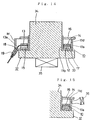
- the following embodiments utilize a gasket to achieve the above object.
- T is an ignition plug having the same structure as that of the foregoing embodiments.
- the plug T has an externally threaded tip end portion t 1 which is threadingly engageable with an internally threaded portion r 3 and.a stepped portion engageable with a plug seat r 2 provided in a plug insertion hole r 1 formed in a cylinder head P.
- the plug insertion hole r 1 has a circular inside peripheral portion whose center axis D is deviated from the axis L of the internally threaded portion r 3 .
- An annular piezoelectric sensor S has a shell 50 composed of concentrical outer side wall and inner side wall defining a hole 51 through which the plug T is inserted.
- Designated as 42 is a guide pipe through which a lead wire 41 extends.
- the shell 50 has such an outer diameter as to form a gap between the shell 50 and the inside periphery of the plug insertion hole r 1 through which gap the guide pipe 42 extends.
- An annular gasket 40 formed, for xample, of copper is interposed between the piezoelectric sensor S and the stepped portion of the ignition plug P.
- the gasket 40 has a center opening 40a through which the plug T is inserted.
- the gasket 40 has such a peripheral portion N that the distance between the portion N and the axis L is greater than the shortest distance R between the axis L and the inside periphery of the plug insertion hole r 1 .
- the gasket 40 has a radially outwardly extending, protruded portion 40b whose periphery N is located outside of a circle having a radius R as shown by a phantom line.
- the protruded portion 40b of the gasket 40 is brought into engagement with the circular inside periphery of the plug insertion hole r 1 upon rotation of thereof about the axis L of the internally threaded portion r 3 of the plug insertion hole r 1 .
- the gasket 40 is also provided with a cut-away portion 40c at such a position that the guide pipe 42 is not engaged by the gasket 40 upon rotation of the gasket 40 during the screwing of the ignition plug T for the attachment thereof to the plug hole r 1 .
- a cut-away portion 40c When a hole is provided in the cylinder head P for the passage of the lead wire 41, it is not necessary to form such a cut-away portion 40c.
- the gasket 40 on the sensor S is rotated by frictional contact with the stepped portion of the plug T to cause the portion N of the protruded portion 40b to be brought into engagement with an inside periphery of the plug hole r 1 so that the gasket 40 is prevented from being further rotated in the screwing direction.
- the sensor S provided below the gasket 40 receive only an axial, pressing force from the rotation of the plug T.
- the shape of the gasket 40 is not limited to that shown in Fig. 21 in which the outer periphery N is circular whose center coincides with the center axis L.
- the gasket 40 is shaped to have an outer periphery N similar to the inside periphery of the plug insertion hole.
- the outer periphery N of the gasket is circular whose center coincides with with the axis D of the plug insertion hole r 1 .
- the gasket of Fig. 24 has a portion N protruded from a circular periphery.
Priority Applications (1)
| Application Number | Priority Date | Filing Date | Title |
|---|---|---|---|
| EP95113826A EP0694773B1 (de) | 1991-04-09 | 1992-04-08 | Vorrichtung zur Erfassung von Zylinderinnendruckänderungen |
Applications Claiming Priority (8)
| Application Number | Priority Date | Filing Date | Title |
|---|---|---|---|
| JP16694191A JP2884200B2 (ja) | 1991-04-09 | 1991-04-09 | 内燃機関のシリンダ内圧力検出装置 |
| JP166941/91 | 1991-04-09 | ||
| JP1991039033U JP2535366Y2 (ja) | 1991-04-25 | 1991-04-25 | 圧力センサーの回り止め構造 |
| JP39033/91 | 1991-04-25 | ||
| JP305232/91 | 1991-10-23 | ||
| JP30523291A JPH05118946A (ja) | 1991-10-23 | 1991-10-23 | シリンダ内圧力検出装置 |
| JP03319907A JP3090515B2 (ja) | 1991-11-06 | 1991-11-06 | 環状圧電センサの組付け方法 |
| JP319907/91 | 1991-11-06 |
Related Child Applications (2)
| Application Number | Title | Priority Date | Filing Date |
|---|---|---|---|
| EP95113826.2 Division-Into | 1992-04-08 | ||
| EP95113826A Division EP0694773B1 (de) | 1991-04-09 | 1992-04-08 | Vorrichtung zur Erfassung von Zylinderinnendruckänderungen |
Publications (3)
| Publication Number | Publication Date |
|---|---|
| EP0508739A2 true EP0508739A2 (de) | 1992-10-14 |
| EP0508739A3 EP0508739A3 (en) | 1993-08-11 |
| EP0508739B1 EP0508739B1 (de) | 1996-12-04 |
Family
ID=27460693
Family Applications (2)
| Application Number | Title | Priority Date | Filing Date |
|---|---|---|---|
| EP92303098A Expired - Lifetime EP0508739B1 (de) | 1991-04-09 | 1992-04-08 | Einrichtung zum Erfassen der Änderung im Innendruck eines Zylinders |
| EP95113826A Expired - Lifetime EP0694773B1 (de) | 1991-04-09 | 1992-04-08 | Vorrichtung zur Erfassung von Zylinderinnendruckänderungen |
Family Applications After (1)
| Application Number | Title | Priority Date | Filing Date |
|---|---|---|---|
| EP95113826A Expired - Lifetime EP0694773B1 (de) | 1991-04-09 | 1992-04-08 | Vorrichtung zur Erfassung von Zylinderinnendruckänderungen |
Country Status (2)
| Country | Link |
|---|---|
| EP (2) | EP0508739B1 (de) |
| DE (1) | DE69215572T2 (de) |
Cited By (5)
| Publication number | Priority date | Publication date | Assignee | Title |
|---|---|---|---|---|
| EP0609787A1 (de) * | 1993-02-03 | 1994-08-10 | NGK Spark Plug Co. Ltd. | Zündkerze mit eingebautem Drucksensor |
| US5753798A (en) * | 1996-06-04 | 1998-05-19 | K. K. Holding Ag | Pressure sensor for gaseous and/or liquid media of internal combustion engines with improved temperature stability |
| EP2884093A1 (de) * | 2013-12-10 | 2015-06-17 | Robert Bosch GmbH | Sensoreinrichtung zur Kraft- oder Druckerfassung, Verfahren zum Herstellen einer Sensoreinrichtung und Kraftstoffinjektor mit einer Sensoreinrichtung |
| CN107152338A (zh) * | 2016-03-03 | 2017-09-12 | 丰田自动车株式会社 | 内燃机 |
| CN109813381A (zh) * | 2017-11-21 | 2019-05-28 | 代傲表计有限公司 | 用于确定测量体积中的压力的测量装置 |
Citations (3)
| Publication number | Priority date | Publication date | Assignee | Title |
|---|---|---|---|---|
| US4566316A (en) * | 1983-01-10 | 1986-01-28 | Nissan Motor Co., Ltd. | Washer type pressure sensor |
| US4602506A (en) * | 1984-06-29 | 1986-07-29 | Nissan Motor Co., Ltd. | Combustion pressure sensor arrangement |
| US4686861A (en) * | 1984-09-26 | 1987-08-18 | Ngk Spark Plug Co., Ltd. | Gasket type pressure sensor |
Family Cites Families (2)
| Publication number | Priority date | Publication date | Assignee | Title |
|---|---|---|---|---|
| DE3025808A1 (de) * | 1979-01-22 | 1982-02-11 | Robert Bosch Gmbh, 7000 Stuttgart | Sensor |
| DE69214498T2 (de) * | 1991-04-25 | 1997-02-20 | Ngk Spark Plug Co | Vorrichtung zur provisorischen Befestigung eines Drucksensors in die Zündkerzenbohrung des Zylinderkopfes |
-
1992
- 1992-04-08 EP EP92303098A patent/EP0508739B1/de not_active Expired - Lifetime
- 1992-04-08 DE DE69215572T patent/DE69215572T2/de not_active Expired - Fee Related
- 1992-04-08 EP EP95113826A patent/EP0694773B1/de not_active Expired - Lifetime
Patent Citations (3)
| Publication number | Priority date | Publication date | Assignee | Title |
|---|---|---|---|---|
| US4566316A (en) * | 1983-01-10 | 1986-01-28 | Nissan Motor Co., Ltd. | Washer type pressure sensor |
| US4602506A (en) * | 1984-06-29 | 1986-07-29 | Nissan Motor Co., Ltd. | Combustion pressure sensor arrangement |
| US4686861A (en) * | 1984-09-26 | 1987-08-18 | Ngk Spark Plug Co., Ltd. | Gasket type pressure sensor |
Cited By (6)
| Publication number | Priority date | Publication date | Assignee | Title |
|---|---|---|---|---|
| EP0609787A1 (de) * | 1993-02-03 | 1994-08-10 | NGK Spark Plug Co. Ltd. | Zündkerze mit eingebautem Drucksensor |
| US5753798A (en) * | 1996-06-04 | 1998-05-19 | K. K. Holding Ag | Pressure sensor for gaseous and/or liquid media of internal combustion engines with improved temperature stability |
| EP2884093A1 (de) * | 2013-12-10 | 2015-06-17 | Robert Bosch GmbH | Sensoreinrichtung zur Kraft- oder Druckerfassung, Verfahren zum Herstellen einer Sensoreinrichtung und Kraftstoffinjektor mit einer Sensoreinrichtung |
| CN107152338A (zh) * | 2016-03-03 | 2017-09-12 | 丰田自动车株式会社 | 内燃机 |
| CN107152338B (zh) * | 2016-03-03 | 2019-08-23 | 丰田自动车株式会社 | 内燃机 |
| CN109813381A (zh) * | 2017-11-21 | 2019-05-28 | 代傲表计有限公司 | 用于确定测量体积中的压力的测量装置 |
Also Published As
| Publication number | Publication date |
|---|---|
| DE69215572T2 (de) | 1997-03-27 |
| EP0508739B1 (de) | 1996-12-04 |
| EP0694773A2 (de) | 1996-01-31 |
| EP0694773A3 (de) | 1996-02-28 |
| EP0508739A3 (en) | 1993-08-11 |
| EP0694773B1 (de) | 1998-06-24 |
| DE69215572D1 (de) | 1997-01-16 |
Similar Documents
| Publication | Publication Date | Title |
|---|---|---|
| US5323643A (en) | Device for detecting change in internal pressure of cylinder | |
| JP4152438B2 (ja) | 測定検出子 | |
| US7614277B2 (en) | Knock sensor | |
| US4909071A (en) | Spark plug pressure sensor | |
| US6279381B1 (en) | Vibration pickup with pressure sheath | |
| EP1555519A1 (de) | Klopfsensor | |
| EP0508739A2 (de) | Einrichtung zum Erfassen der Änderung im Innendruck eines Zylinders | |
| JP2006112953A (ja) | ノックセンサ及びその製造方法 | |
| KR100602774B1 (ko) | 내연 기관의 노킹 센서 및 그 제조 방법 | |
| EP0637736A2 (de) | Piezoelektrischer Drucksensor und Verfahren zu seiner Herstellung | |
| US20030121312A1 (en) | Non-resonance type knock sensor | |
| US20040025854A1 (en) | Ignition device for an internal combustion engine | |
| KR920007413Y1 (ko) | 진동검출기 | |
| JP4706901B2 (ja) | バッテリーターミナル | |
| US5144837A (en) | Acceleration detector | |
| EP0047660A1 (de) | Beschleunigungsmesser | |
| JP3090515B2 (ja) | 環状圧電センサの組付け方法 | |
| JP3241048U (ja) | 共振レベルスイッチ構造 | |
| JPH06281524A (ja) | シリンダ内圧検出装置及びその高さ調整方法 | |
| JPH0631396Y2 (ja) | シリンダ内圧センサ | |
| JPH0631397Y2 (ja) | シリンダ内圧センサ | |
| JP2523239Y2 (ja) | 環状圧電センサ | |
| JPH05133834A (ja) | 環状圧電センサの組付け方法 | |
| US4679431A (en) | Probe assemblies including such mounts | |
| JPH05157652A (ja) | 環状圧電センサの組付け方法 |
Legal Events
| Date | Code | Title | Description |
|---|---|---|---|
| PUAI | Public reference made under article 153(3) epc to a published international application that has entered the european phase |
Free format text: ORIGINAL CODE: 0009012 |
|
| AK | Designated contracting states |
Kind code of ref document: A2 Designated state(s): DE FR GB |
|
| PUAL | Search report despatched |
Free format text: ORIGINAL CODE: 0009013 |
|
| AK | Designated contracting states |
Kind code of ref document: A3 Designated state(s): DE FR GB |
|
| 17P | Request for examination filed |
Effective date: 19940208 |
|
| 17Q | First examination report despatched |
Effective date: 19950224 |
|
| GRAG | Despatch of communication of intention to grant |
Free format text: ORIGINAL CODE: EPIDOS AGRA |
|
| GRAH | Despatch of communication of intention to grant a patent |
Free format text: ORIGINAL CODE: EPIDOS IGRA |
|
| GRAH | Despatch of communication of intention to grant a patent |
Free format text: ORIGINAL CODE: EPIDOS IGRA |
|
| GRAA | (expected) grant |
Free format text: ORIGINAL CODE: 0009210 |
|
| AK | Designated contracting states |
Kind code of ref document: B1 Designated state(s): DE FR GB |
|
| DX | Miscellaneous (deleted) | ||
| REF | Corresponds to: |
Ref document number: 69215572 Country of ref document: DE Date of ref document: 19970116 |
|
| ET | Fr: translation filed | ||
| PLBE | No opposition filed within time limit |
Free format text: ORIGINAL CODE: 0009261 |
|
| STAA | Information on the status of an ep patent application or granted ep patent |
Free format text: STATUS: NO OPPOSITION FILED WITHIN TIME LIMIT |
|
| 26N | No opposition filed | ||
| PGFP | Annual fee paid to national office [announced via postgrant information from national office to epo] |
Ref country code: GB Payment date: 19990408 Year of fee payment: 8 |
|
| PGFP | Annual fee paid to national office [announced via postgrant information from national office to epo] |
Ref country code: FR Payment date: 19990409 Year of fee payment: 8 |
|
| PGFP | Annual fee paid to national office [announced via postgrant information from national office to epo] |
Ref country code: DE Payment date: 19990419 Year of fee payment: 8 |
|
| PG25 | Lapsed in a contracting state [announced via postgrant information from national office to epo] |
Ref country code: GB Free format text: LAPSE BECAUSE OF NON-PAYMENT OF DUE FEES Effective date: 20000408 |
|
| GBPC | Gb: european patent ceased through non-payment of renewal fee |
Effective date: 20000408 |
|
| PG25 | Lapsed in a contracting state [announced via postgrant information from national office to epo] |
Ref country code: FR Free format text: LAPSE BECAUSE OF NON-PAYMENT OF DUE FEES Effective date: 20001229 |
|
| PG25 | Lapsed in a contracting state [announced via postgrant information from national office to epo] |
Ref country code: DE Free format text: LAPSE BECAUSE OF NON-PAYMENT OF DUE FEES Effective date: 20010201 |
|
| REG | Reference to a national code |
Ref country code: FR Ref legal event code: ST |