EP0508732A2 - Injection molding method - Google Patents
Injection molding method Download PDFInfo
- Publication number
- EP0508732A2 EP0508732A2 EP92303089A EP92303089A EP0508732A2 EP 0508732 A2 EP0508732 A2 EP 0508732A2 EP 92303089 A EP92303089 A EP 92303089A EP 92303089 A EP92303089 A EP 92303089A EP 0508732 A2 EP0508732 A2 EP 0508732A2
- Authority
- EP
- European Patent Office
- Prior art keywords
- resin
- weld
- valve
- well
- cavity
- Prior art date
- Legal status (The legal status is an assumption and is not a legal conclusion. Google has not performed a legal analysis and makes no representation as to the accuracy of the status listed.)
- Granted
Links
Images


Classifications
-
- B—PERFORMING OPERATIONS; TRANSPORTING
- B29—WORKING OF PLASTICS; WORKING OF SUBSTANCES IN A PLASTIC STATE IN GENERAL
- B29C—SHAPING OR JOINING OF PLASTICS; SHAPING OF MATERIAL IN A PLASTIC STATE, NOT OTHERWISE PROVIDED FOR; AFTER-TREATMENT OF THE SHAPED PRODUCTS, e.g. REPAIRING
- B29C45/00—Injection moulding, i.e. forcing the required volume of moulding material through a nozzle into a closed mould; Apparatus therefor
- B29C45/17—Component parts, details or accessories; Auxiliary operations
- B29C45/76—Measuring, controlling or regulating
-
- B—PERFORMING OPERATIONS; TRANSPORTING
- B29—WORKING OF PLASTICS; WORKING OF SUBSTANCES IN A PLASTIC STATE IN GENERAL
- B29C—SHAPING OR JOINING OF PLASTICS; SHAPING OF MATERIAL IN A PLASTIC STATE, NOT OTHERWISE PROVIDED FOR; AFTER-TREATMENT OF THE SHAPED PRODUCTS, e.g. REPAIRING
- B29C45/00—Injection moulding, i.e. forcing the required volume of moulding material through a nozzle into a closed mould; Apparatus therefor
- B29C45/0025—Preventing defects on the moulded article, e.g. weld lines, shrinkage marks
- B29C2045/0039—Preventing defects on the moulded article, e.g. weld lines, shrinkage marks intermixing the injected material front at the weld line, e.g. by applying vibrations to the melt front
-
- B—PERFORMING OPERATIONS; TRANSPORTING
- B29—WORKING OF PLASTICS; WORKING OF SUBSTANCES IN A PLASTIC STATE IN GENERAL
- B29C—SHAPING OR JOINING OF PLASTICS; SHAPING OF MATERIAL IN A PLASTIC STATE, NOT OTHERWISE PROVIDED FOR; AFTER-TREATMENT OF THE SHAPED PRODUCTS, e.g. REPAIRING
- B29C45/00—Injection moulding, i.e. forcing the required volume of moulding material through a nozzle into a closed mould; Apparatus therefor
- B29C45/17—Component parts, details or accessories; Auxiliary operations
- B29C45/26—Moulds
- B29C45/2628—Moulds with mould parts forming holes in or through the moulded article, e.g. for bearing cages
-
- B—PERFORMING OPERATIONS; TRANSPORTING
- B29—WORKING OF PLASTICS; WORKING OF SUBSTANCES IN A PLASTIC STATE IN GENERAL
- B29C—SHAPING OR JOINING OF PLASTICS; SHAPING OF MATERIAL IN A PLASTIC STATE, NOT OTHERWISE PROVIDED FOR; AFTER-TREATMENT OF THE SHAPED PRODUCTS, e.g. REPAIRING
- B29C45/00—Injection moulding, i.e. forcing the required volume of moulding material through a nozzle into a closed mould; Apparatus therefor
- B29C45/17—Component parts, details or accessories; Auxiliary operations
- B29C45/26—Moulds
- B29C45/2669—Moulds with means for removing excess material, e.g. with overflow cavities
Definitions
- the present invention relates to an injection molding method, an injection mold, and an injection molded article of a thermoplastic resin. More particularly, the present invention is concerned with an injection molding method and an injection mold which can remarkably improve the strength around a weld of a molded article as opposed to the conventional method which inherently gives rise to a weld having a very low strength, and can improve the appearance of the weld, and an injection molded article having an improved weld strength, etc.
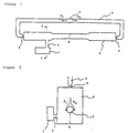
- Fig. 1 is a schematic plan view of one embodiment of the mold of the present invention wherein a resin well is provided on a typical mold (molded article) shown in Fig. 12 which gives rise to a weld.
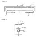
- Fig. 2 is a schematic plan view of one embodiment of the mold of the present invention wherein a resin well is provided on a typical mold (molded article) shown in Fig. 13 which gives rise to a weld.
- Fig. 3 is a schematic cross-sectional view of one embodiment of a structure of a valve to be provided at the inlet of the resin well, and corresponds to a cross section taken along line I-I of Fig. 1 when the valve is provided.
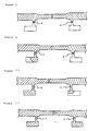
- Fig. 4 is a schematic diagram of a principal part of a mold showing the process of filling a resin in the case where a valve is provided at the inlet of the resin well of the mold shown in Fig. 1 and molding is conducted while controlling the pouring of the resin in the resin well.
- X represents a closed state of the valve
- Y represents an opened state of the valve.
- Fig. 5 is a schematic diagram of a principal part of a mold showing the process of filling a resin in the case where a valve is provided at the inlet of the resin well of the mold shown in Fig. 1 and molding is conducted while controlling the pouring of the resin in the resin well.
- X represents a closed state of the valve
- Y represents an opened state of the valve.
- Fig. 6 is a schematic diagram of a principal part of a mold showing the process of filling a resin in the case where a valve is provided at the inlet of the resin well of the mold shown in Fig. 1 and molding is conducted while controlling the pouring of the resin in the resin well.
- X represents a closed state of the valve
- Y represents an opened state of the valve.
- Fig. 7 is a schematic diagram of a principal part of a mold showing the process of filling a resin in the case where a switching valve is provided at the inlet of the resin well of the mold shown in Fig. 1 and molding is conducted while controlling the pouring of the resin in the resin well.
- X represents a closed state of the valve
- Y represents an opened state of the valve.
- Fig. 8 is a schematic diagram of a principal part of a mold showing the process of filling a resin in the case where two resin wells each provided with a valve at the inlet are provided on the mold shown in Fig. 1 and molding is conducted while controlling alternate pouring of the resin in each resin well.
- X represents a closed state of each valve
- Y represents an opened state of each valve.
- Fig. 9 is a schematic diagram of a principal part of a mold showing the process of filling a resin in the case where two resin wells each provided with a valve at the inlet are provided on the mold shown in Fig. 1 and molding is conducted while controlling alternate pouring of the resin in each resin well.
- X represents a closed state of each valve
- Y represents an opened state of each valve.
- Fig. 10 is a schematic diagram of a principal part of a mold showing the process of filling a resin in the case where two resin wells each provided with a valve at the inlet are provided on the mold shown in Fig. 1 and molding is conducted while controlling alternate pouring of the resin in each resin well.
- X represents a closed state of each valve
- Y represents an opened state of each valve.
- Fig. 11 is a schematic diagram of a principal part of a mold showing the process of filling a resin in the case where two resin wells each provided with a valve at the inlet are provided on the mold shown in Fig. 1 and molding is conducted while controlling alternate pouring of the resin in each resin well.
- X represents a closed state of each valve
- Y represents an opened state of each valve.
- Fig. 12 is a schematic plan view of a typical embodiment of a mold (a molded article) which gives rise to a weld.
- Fig. 13 is a schematic plan view of a typical embodiment of a mold (a molded article) which gives rise to a weld.
- the molten resin injected and filled into the cavity is separated into streams due to a difference in the filling rate of the resin between the portion having a larger thickness and the portion having a smaller thickness, so that a weld often forms at a portion where the separated resin streams are united into a single stream.
- the weld of the molded article is formed due to a combination of the above-described various factors, so that it is very difficult to produce a practical molded article having a complicated shape but being free from a weld.
- Such a weld poses a very serious problem that not only a linear pattern called weld mark occurs to thereby deteriorates the appearance, but also the strength of the formed molded article is much lower than the inherent strength of the resin, because the molten resin streams are merely united and fused with each other to fail in achieving homogeneous mixing of the resin.
- Japanese Patent Laid-Open No. 71459/1973 discloses a molding process which comprises filling a resin in a mold provided with a resin well at a position where weld occurs and pushing back the resin contained in the resin well into the mold, thereby improving the strength of the weld
- Japanese Patent Laid-Open No. 202414/1990 discloses a molding process which comprises injecting and filling a resin into a cavity through a plurality of gates provided with a valve to form resin streams, uniting the resin streams and then operating the valve to give rise to a difference in the resin filling pressure to disturb the weld, thereby improving the strength of the weld.
- the present inventors have made intensive studies with a view to solving the above-described problem and producing a molded article having an improved weld strength and, as a result, have found a method of efficiently improving a weld strength and a mold to be used for this purpose wherein the resin is caused to migrate while the resin maintains the fluidity in the cavity after the formation of a weld, thereby disturbing the orientation of the resin or filler at the weld.
- the present invention provides an injection molding method for a thermoplastic resin, wherein use is made of a mold provided with a resin well protruding from a molded article cavity (6) or a runner (4) on at least one of separated resin passages starting from a point where an injected molten filling resin Is separated into streams and terminating at a weld formed by the union of the separated resin streams, and a resin is poured into the resin well after the formation of the weld through the feed of the molten resin into the molded article cavity to cause the migration of the resin at the weld, thus forcing the resin on one side of the weld into the resin on the other side of the weld to strengthen the weld,
- the invention provides a mold for injection-molding a thermoplastic resin having a resin well protruding from a molded article cavity or a runner on at least one of separated resin passages starting from a point where an injected molten filling resin is separated into streams and terminating at a weld formed by the union of the separated resin streams so that a resin is poured into the resin well after the formation of a weld through the feed of the molten resin into the molded article cavity to cause the migration of the resin at the weld, thus forcing the resin on one side of the weld into the resin on the other side of the weld to strengthen the weld,
- the invention also provides an injection molded article made by the above-described injection molding method.
- Figs. 1 and 2 show embodiments of a mold while taking a mold (a molded article) shown in Fig. 12 and a mold (a molded article) shown in Fig. 13, respectively, as the example of a typical mold liable to give rise to a weld.
- a resin well protruding from a molded article cavity or sprue is provided at a predetermined position, that is, on at least one of resin passages starting from a point where an injected molten filling resin is separated into streams and terminating at a weld formed by the union of the separated resin streams.
- a molten resin is further poured into the resin well 1 through the utilization of the injection pressure applied to the resin or the dwelling to give rise to a pressure difference between both sides of the weld, so that the resin on the side not provided with a resin well is forced into the resin on the side provided with the resin well to disturb the orientation, etc., of the resin or filler at the weld, which contributes to an improvement in the strength of the weld and makes the weld line unnoticeable.
- the thickness of the inlet of the resin well be 0.2 to 0.7 time that of the thickness of the molded article.
- valve so that the pouring of the resin into the resin well is forcibly controlled.
- the valve to be provided at the inlet of the resin well is usually closed and may have such a structure that it spontaneously opens in response to the injection pressure or dwelling after the filling of the molten resin into the cavity.
- the valve may have such a structure that it can be forcibly opened and closed by a separately provided drive mechanism.
- a sensor capable of detecting the state of filling of the resin into the cavity may be provided within the mold or on the side of the molding machine so that the state of the filling of the resin into the cavity is detected by the sensor and the drive mechanism operates in response to the detected signal to open the valve.
- Fig. 3 is an embodiment of such a structure that the valve spontaneously opens in response to the pressure applied to the cavity.
- a piston valve 8 having a diagonally cut top is pushed up through the utilization of a spring pressure or the like.
- the inlet of the resin well is closed during the filling of the resin into the cavity.
- a component force which pushes down the piston valve occurs.
- this component force exceeds the pushing force, the valve comes down, which causes the resin to be poured into the resin well.
- the valve having the above-described structure is very simple and useful from the viewpoint of the apparatus.
- valve opens in response to the pressure from the cavity
- a drive mechanism When the valve is opened and closed by means of a drive mechanism, it is possible to open the valve immediately before the formation of a weld as far as the resin is poured into the resin well also after the formation of the weld.
- Figs. 4 to 7 schematically show the state of filling of the resin with the elapse of the time in the case where molding is conducted while controlling the pouring of the resin into the resin well through the use of the mold provided with the above-described valve.
- the molding is conducted by a method which comprises, after the formation of a weld through the filling of a molten resin, pouring a resin into a resin well provided on one side of the weld and subsequently pouring the resin into a resin well provided on the other side, or a method wherein a resin is alternately poured into resin wells provided on both sides of the weld, the weld can be more efficiently disturbed by the alternate migration of the resin streams at the weld and the forcing of the resin, which renders this method very favorable for improving the weld strength and the appearance.
- the position and capacity of the resin well are related to the solidification speed of the resin, the volume of the molded article, the distance or volume between the resin separating point and the weld, and further the molding conditions such as resin temperature and injection pressure, and hence cannot be simply specified.
- the capacity of the resin well is preferably S x 5 (mm 3 ) or more, still preferably S x 10 (mm 3 ) or more, wherein S represents the sectional area (mm 2 ) of the molded article along the weld.
- the injection molding method and mold according to the present invention can be applied to the injection molding of any of known thermoplastic resins, they can be particularly usefully applied to the injection molding of a thermoplastic resin which causes a remarkable lowering in the weld strength in the conventional molding method.
- a thermoplastic resin containing an inorganic filler, particularly a fibrous filler is molded by the conventional method, the strength at the weld is much lower than that of the other portions, since the inorganic filler, particularly a fibrous filler, orients along both sides of the weld.
- the molding method and mold according to the present invention enable the strength of the weld to be sufficiently improved by virtue of efficient turbulence of the orientation at the weld.
- thermoplastic resin containing a fibrous filler having a mean fiber length of 3 mm or more a strong orientation of the fiber is observed along the weld, so that a lowering in the weld strength occurs unfavorably.
- the molding method and mold according to the present invention are useful particularly for the molding of such a resin composition. Also in the molding of a resin composition mainly composed of a crystalline thermoplastic resin, a similar problem is liable to occur due to the orientation of the crystalline resin along the weld.
- the molding method and mold according to the present invention is very useful also for the molding of the resin composition of this type.
- the injection molding method and mold according to the present invention wherein use is made of a mold provided with a resin well protruding from a molded article cavity or a runner on at least one of separated resin passages starting from a point where an injected molten filling resin is separated into streams and terminating at a weld formed by the union of the separated resin streams and a resin is poured into the resin well after the formation of a weld through the feed of a molten resin into the molded article cavity to cause the migration of the resin at the weld, thus forcing the resin on one side of the weld into the resin on the other side of the weld, has excellent features that not only the weld can be very efficiently strengthened but also the appearance is improved, which renders the present invention very valuable from the practical viewpoint.
- Resin compositions in the form of a pellet having a length of 12 mm comprising a polypropylene resin (PP), a polyamide 66 resin (PA66) or a polyethylene terephthalate resin (PET) and 40% by weight of a long glass fiber (GF) were injection-molded though the use of an injection mold having a structure as shown in Fig. 1 and provided with a valve at the inlet of the resin well as shown in Fig. 3.
- the long glass fiber had substantially the same length as that of the pellet (mean fiber length: about 12 mm) and oriented in the direction parallel to the longitudinal direction of the pellet.
- a molded article was prepared in the same manner as that describe above, except that the molding was conducted with the inlet of the resin well of the mold shown in Fig. 1 being closed.
Abstract
Description
- The present invention relates to an injection molding method, an injection mold, and an injection molded article of a thermoplastic resin. More particularly, the present invention is concerned with an injection molding method and an injection mold which can remarkably improve the strength around a weld of a molded article as opposed to the conventional method which inherently gives rise to a weld having a very low strength, and can improve the appearance of the weld, and an injection molded article having an improved weld strength, etc.
- Fig. 1 is a schematic plan view of one embodiment of the mold of the present invention wherein a resin well is provided on a typical mold (molded article) shown in Fig. 12 which gives rise to a weld.
- Fig. 2 is a schematic plan view of one embodiment of the mold of the present invention wherein a resin well is provided on a typical mold (molded article) shown in Fig. 13 which gives rise to a weld.
- Fig. 3 is a schematic cross-sectional view of one embodiment of a structure of a valve to be provided at the inlet of the resin well, and corresponds to a cross section taken along line I-I of Fig. 1 when the valve is provided.
- Fig. 4 is a schematic diagram of a principal part of a mold showing the process of filling a resin in the case where a valve is provided at the inlet of the resin well of the mold shown in Fig. 1 and molding is conducted while controlling the pouring of the resin in the resin well. In the drawing, X represents a closed state of the valve, and Y represents an opened state of the valve.
- Fig. 5 is a schematic diagram of a principal part of a mold showing the process of filling a resin in the case where a valve is provided at the inlet of the resin well of the mold shown in Fig. 1 and molding is conducted while controlling the pouring of the resin in the resin well. In the drawing, X represents a closed state of the valve, and Y represents an opened state of the valve.
- Fig. 6 is a schematic diagram of a principal part of a mold showing the process of filling a resin in the case where a valve is provided at the inlet of the resin well of the mold shown in Fig. 1 and molding is conducted while controlling the pouring of the resin in the resin well. In the drawing, X represents a closed state of the valve, and Y represents an opened state of the valve.
- Fig. 7 is a schematic diagram of a principal part of a mold showing the process of filling a resin in the case where a switching valve is provided at the inlet of the resin well of the mold shown in Fig. 1 and molding is conducted while controlling the pouring of the resin in the resin well. In the drawing, X represents a closed state of the valve, and Y represents an opened state of the valve.
- Fig. 8 is a schematic diagram of a principal part of a mold showing the process of filling a resin in the case where two resin wells each provided with a valve at the inlet are provided on the mold shown in Fig. 1 and molding is conducted while controlling alternate pouring of the resin in each resin well. In the drawing, X represents a closed state of each valve, and Y represents an opened state of each valve.
- Fig. 9 is a schematic diagram of a principal part of a mold showing the process of filling a resin in the case where two resin wells each provided with a valve at the inlet are provided on the mold shown in Fig. 1 and molding is conducted while controlling alternate pouring of the resin in each resin well. In the drawing, X represents a closed state of each valve, and Y represents an opened state of each valve.
- Fig. 10 is a schematic diagram of a principal part of a mold showing the process of filling a resin in the case where two resin wells each provided with a valve at the inlet are provided on the mold shown in Fig. 1 and molding is conducted while controlling alternate pouring of the resin in each resin well. In the drawing, X represents a closed state of each valve, and Y represents an opened state of each valve.
- Fig. 11 is a schematic diagram of a principal part of a mold showing the process of filling a resin in the case where two resin wells each provided with a valve at the inlet are provided on the mold shown in Fig. 1 and molding is conducted while controlling alternate pouring of the resin in each resin well. In the drawing, X represents a closed state of each valve, and Y represents an opened state of each valve.
- Fig. 12 is a schematic plan view of a typical embodiment of a mold (a molded article) which gives rise to a weld.
- Fig. 13 is a schematic plan view of a typical embodiment of a mold (a molded article) which gives rise to a weld.
-
- 1
- : resin well,
- 2
- : inlet of resin well,
- 3
- : sprue,
- 4
- : runner,
- 5
- : gate,
- 6
- : cavity,
- 7
- : core,
- 8
- : piston valve,
- 9
- : spring,
- 10
- : fixed mold,
- 11
- : movable mold,
- 12
- : block (insert) for resin well, and
- 13
- : block (insert) for inlet of resin well (piston valve).
- In the mold shown in Fig. 12, when a molten resin is injected and filled into a
single cavity 6 through a plurality ofgates core 7 or the like provided within the cavity as shown in Fig. 13, a weld forms at a position B where the separated resin streams are united into a single stream. Further, also when the molded article has a portion having an uneven thickness, the molten resin injected and filled into the cavity is separated into streams due to a difference in the filling rate of the resin between the portion having a larger thickness and the portion having a smaller thickness, so that a weld often forms at a portion where the separated resin streams are united into a single stream. In many cases, the weld of the molded article is formed due to a combination of the above-described various factors, so that it is very difficult to produce a practical molded article having a complicated shape but being free from a weld. Such a weld poses a very serious problem that not only a linear pattern called weld mark occurs to thereby deteriorates the appearance, but also the strength of the formed molded article is much lower than the inherent strength of the resin, because the molten resin streams are merely united and fused with each other to fail in achieving homogeneous mixing of the resin. - In order to solve the problem of the lowering in the strength of the weld by molding, Japanese Patent Laid-Open No. 71459/1973 discloses a molding process which comprises filling a resin in a mold provided with a resin well at a position where weld occurs and pushing back the resin contained in the resin well into the mold, thereby improving the strength of the weld, and Japanese Patent Laid-Open No. 202414/1990 discloses a molding process which comprises injecting and filling a resin into a cavity through a plurality of gates provided with a valve to form resin streams, uniting the resin streams and then operating the valve to give rise to a difference in the resin filling pressure to disturb the weld, thereby improving the strength of the weld.
- In these processes, however, it is difficult to disturb the orientation of the resin or filler at the weld through the occurrence of a sufficient resin stream there, so that no satisfactory improvement in the strength of the weld can be attained.
- The present inventors have made intensive studies with a view to solving the above-described problem and producing a molded article having an improved weld strength and, as a result, have found a method of efficiently improving a weld strength and a mold to be used for this purpose wherein the resin is caused to migrate while the resin maintains the fluidity in the cavity after the formation of a weld, thereby disturbing the orientation of the resin or filler at the weld.
- Accordingly, the present invention provides an injection molding method for a thermoplastic resin, wherein use is made of a mold provided with a resin well protruding from a molded article cavity (6) or a runner (4) on at least one of separated resin passages starting from a point where an injected molten filling resin Is separated into streams and terminating at a weld formed by the union of the separated resin streams, and a resin is poured into the resin well after the formation of the weld through the feed of the molten resin into the molded article cavity to cause the migration of the resin at the weld, thus forcing the resin on one side of the weld into the resin on the other side of the weld to strengthen the weld,
- In another embodiment the invention provides a mold for injection-molding a thermoplastic resin having a resin well protruding from a molded article cavity or a runner on at least one of separated resin passages starting from a point where an injected molten filling resin is separated into streams and terminating at a weld formed by the union of the separated resin streams so that a resin is poured into the resin well after the formation of a weld through the feed of the molten resin into the molded article cavity to cause the migration of the resin at the weld, thus forcing the resin on one side of the weld into the resin on the other side of the weld to strengthen the weld, The invention also provides an injection molded article made by the above-described injection molding method.
- The mold and molding method according to the present invention will now be described in more detail with reference to the attached drawings.
- Figs. 1 and 2 show embodiments of a mold while taking a mold (a molded article) shown in Fig. 12 and a mold (a molded article) shown in Fig. 13, respectively, as the example of a typical mold liable to give rise to a weld. In these embodiments, in order to improve the weld strength, etc., according to the present invention, a resin well protruding from a molded article cavity or sprue is provided at a predetermined position, that is, on at least one of resin passages starting from a point where an injected molten filling resin is separated into streams and terminating at a weld formed by the union of the separated resin streams. It is a matter of course that most of the practical molds (molded articles) rarely have such a simple form, and the manner of filling the molten resin into the cavity, the weld formation process, etc., are more complicate. Fundamentally, however, the constitution of the mold and the molding method may be as has been described above and will be described below.
- In molding a molded article through the use of the above-described mold, when no resin well is provided, that is, in the molds shown in Figs. 12 and 13, the injected molten filling resin is separated into resin streams A1 and A2 underneath a
sprue 3 in the case of the mold shown in Fig. 12 and in front of acore 7 in the case of the mold shown in Fig. 13, and a weld is formed at a point B where the separated resin streams are united. In the above-described weld, the front ends of the two separated resin streams come into contact with each other and apparently adhere to each other, and the resin or filler contained in the resin orients with the weld therebetween. Thus the resin streams are not in a homogeneously mixed state, so that the strength becomes low unfavorably. Further, a line called weld line occurs, which deteriorates the appearance. - On the other hand, in the molding wherein use is made of molds as shown in Figs. 1 and 2 which are provided with a resin well 1 at a predetermined position according to the present invention, after the injected molten filling resin is separated into resin streams A1 and A2 and a weld is formed at a point B where these streams are united, a molten resin is further poured into the resin well 1 through the utilization of the injection pressure applied to the resin or the dwelling to give rise to a pressure difference between both sides of the weld, so that the resin on the side not provided with a resin well is forced into the resin on the side provided with the resin well to disturb the orientation, etc., of the resin or filler at the weld, which contributes to an improvement in the strength of the weld and makes the weld line unnoticeable.
- In the above-described molding method, before a weld is formed by the filled molten resin, part of the resin often pours into the resin well depending upon the size of the inlet of the well, the viscosity of the molten resin, etc. In this case, however, the resin well is not completely filled with this resin, and a space into which the resin is poured after the formation of a weld is left. Therefore, fundamentally, there occurs no problem as far as the fluidity is maintained. In this case, the weld is initially formed at a position deviated from the point B towards the resin well, and the migration of the resin occurs at the weld. In order to minimize the pouring of the resin into the resin well during the filling of the molten resin and to efficiently pour the resin into the resin well after the formation of the weld, it is generally preferred that the thickness of the inlet of the resin well be 0.2 to 0.7 time that of the thickness of the molded article.
- When the inlet of the resin well is opened and the resin pours into the resin well during the filling of the molten resin, however, a lowering in the efficiency of the resin well is unavoidable.
- Therefore, in order to allow the resin well to function more efficiently without fail, it is preferred to provide a valve so that the pouring of the resin into the resin well is forcibly controlled. The valve to be provided at the inlet of the resin well is usually closed and may have such a structure that it spontaneously opens in response to the injection pressure or dwelling after the filling of the molten resin into the cavity. Alternatively, the valve may have such a structure that it can be forcibly opened and closed by a separately provided drive mechanism. In this case, a sensor capable of detecting the state of filling of the resin into the cavity may be provided within the mold or on the side of the molding machine so that the state of the filling of the resin into the cavity is detected by the sensor and the drive mechanism operates in response to the detected signal to open the valve. Alternatively, the time necessary for forming the weld may be previously measured so that the drive mechanism may operate after a predetermined period of time to open the valve. Fig. 3 is an embodiment of such a structure that the valve spontaneously opens in response to the pressure applied to the cavity. In this embodiment, a
piston valve 8 having a diagonally cut top is pushed up through the utilization of a spring pressure or the like. The inlet of the resin well is closed during the filling of the resin into the cavity. When a pressure from the cavity after filling the resin into the cavity is applied to the diagonally cut portion, a component force which pushes down the piston valve occurs. When this component force exceeds the pushing force, the valve comes down, which causes the resin to be poured into the resin well. The valve having the above-described structure is very simple and useful from the viewpoint of the apparatus. - In the above-described embodiment wherein the valve opens in response to the pressure from the cavity, it is preferred to conduct setting in such a manner that the valve opens when a pressure of 30 to 500 kg/cm2 is applied thereto. When the valve is opened and closed by means of a drive mechanism, it is possible to open the valve immediately before the formation of a weld as far as the resin is poured into the resin well also after the formation of the weld. Figs. 4 to 7 schematically show the state of filling of the resin with the elapse of the time in the case where molding is conducted while controlling the pouring of the resin into the resin well through the use of the mold provided with the above-described valve.
- In the above-described method wherein a valve is provided and, after a molten resin is filled into the cavity with the valve closed, the valve is opened to pour the resin into the resin well, the migration and forcing of the resin at the weld are efficiently conducted, which renders this method useful particularly for improving the weld strength and the appearance.
- In the mold according to the present invention, it is also possible to provide a plurality of resin wells. These wells can be provided by any of a method wherein these wells are provided on only one of the separated resin passages wherein the separated resin streams are united to form a weld, and a method wherein at least one well is provided on each of the separated resin passages. In particular, when use is made of a mold having a resin well provided by the latter method and the molding is conducted by a method which comprises, after the formation of a weld through the filling of a molten resin, pouring a resin into a resin well provided on one side of the weld and subsequently pouring the resin into a resin well provided on the other side, or a method wherein a resin is alternately poured into resin wells provided on both sides of the weld, the weld can be more efficiently disturbed by the alternate migration of the resin streams at the weld and the forcing of the resin, which renders this method very favorable for improving the weld strength and the appearance. Figs. 8 to 11 schematically show the state of filling and migration of the resin with the elapse of the time in the above-described molding procedure. In the mold used in the above-described molding, it is particularly useful to provide a valve at the inlet of each resin well so that alternate pouring of the resin into each resin well can be controlled.
- In the mold of the present invention, the position and capacity of the resin well are related to the solidification speed of the resin, the volume of the molded article, the distance or volume between the resin separating point and the weld, and further the molding conditions such as resin temperature and injection pressure, and hence cannot be simply specified. However, what is important is to provide, after consideration of these factors, a resin well having a suitable capacity at a position where the migration and forcing of the resin at the weld efficiently occur after the formation of a weld. Generally speaking, the capacity of the resin well is preferably S x 5 (mm3) or more, still preferably S x 10 (mm3) or more, wherein S represents the sectional area (mm2) of the molded article along the weld.
- Further, in the present invention, it is also possible to use the resin well as the cavity of other molded article.
- Although the injection molding method and mold according to the present invention can be applied to the injection molding of any of known thermoplastic resins, they can be particularly usefully applied to the injection molding of a thermoplastic resin which causes a remarkable lowering in the weld strength in the conventional molding method. For example, when a thermoplastic resin containing an inorganic filler, particularly a fibrous filler, is molded by the conventional method, the strength at the weld is much lower than that of the other portions, since the inorganic filler, particularly a fibrous filler, orients along both sides of the weld. By contrast, the molding method and mold according to the present invention enable the strength of the weld to be sufficiently improved by virtue of efficient turbulence of the orientation at the weld. Among others, in the molding of a thermoplastic resin containing a fibrous filler having a mean fiber length of 3 mm or more, a strong orientation of the fiber is observed along the weld, so that a lowering in the weld strength occurs unfavorably. The molding method and mold according to the present invention are useful particularly for the molding of such a resin composition. Also in the molding of a resin composition mainly composed of a crystalline thermoplastic resin, a similar problem is liable to occur due to the orientation of the crystalline resin along the weld. The molding method and mold according to the present invention is very useful also for the molding of the resin composition of this type.
- As is apparent from the foregoing description, in the injection molding of a thermoplastic resin which gives rise to a weld and provides only a very small strength according to the conventional method, the injection molding method and mold according to the present invention wherein use is made of a mold provided with a resin well protruding from a molded article cavity or a runner on at least one of separated resin passages starting from a point where an injected molten filling resin is separated into streams and terminating at a weld formed by the union of the separated resin streams and a resin is poured into the resin well after the formation of a weld through the feed of a molten resin into the molded article cavity to cause the migration of the resin at the weld, thus forcing the resin on one side of the weld into the resin on the other side of the weld, has excellent features that not only the weld can be very efficiently strengthened but also the appearance is improved, which renders the present invention very valuable from the practical viewpoint.
- The present invention will now be described in more detail with reference to the following Examples, though it is not limited to these Examples only.
- Resin compositions in the form of a pellet having a length of 12 mm, comprising a polypropylene resin (PP), a polyamide 66 resin (PA66) or a polyethylene terephthalate resin (PET) and 40% by weight of a long glass fiber (GF) were injection-molded though the use of an injection mold having a structure as shown in Fig. 1 and provided with a valve at the inlet of the resin well as shown in Fig. 3. In these resin compositions, the long glass fiber had substantially the same length as that of the pellet (mean fiber length: about 12 mm) and oriented in the direction parallel to the longitudinal direction of the pellet.
- The constructions of main sections of the mold used herein and molding conditions were as follows.
Dimension around weld of molded article:
20 mm in width x 4 mm in thickness
Resin well:
dimension = 40 mm x 15 mm x 15 mm in thickness
configuration of inlet = 7 mm in width x 4 mm in thickness
Valve: regulated so that it is opened in response to a pressure of 300 kg/cm2 from the cavity.
Molding conditions:
injection pressure = 1400 kg/cm2
dwelling pressure = 440 kg/cm2 - For comparison, a molded article was prepared in the same manner as that describe above, except that the molding was conducted with the inlet of the resin well of the mold shown in Fig. 1 being closed.
- These molded articles were subjected to the measurement of tensile strength and elongation. Further, the appearance of the weld of the molded article (whether or not the weld line was present) was observed with the naked eye. The results are given in Table 1.

Claims (16)
- An injection molding method for a thermoplastic resin, characterised by the use of a mold provided with a resin well protruding from a molded article cavity or a runner on at least one of separated resin passages starting from a point where an injected molten filling resin is separated into streams and terminating at a weld formed by the union of the separated resin streams, and a resin is poured into the resin well after the formation of the weld through the feed of the molten resin into the molded article cavity to cause the migration of the resin at the weld, thus forcing the resin on one side of the weld into the resin on the other side of the weld to strengthen the weld.
- The method according to claim 1, characterised in that the resin well is provided with a valve at its inlet and, after the molten resin is fed into the molded article cavity wit the valve closed, the valve is opened to pour the resin into the resin well.
- The method according to claim 2, characterised in that the valve is closed during the filling of the molten resin into the cavity, and is opened in response to a pressure applied from the cavity after filling the molten resin into the cavity to pour the resin into the resin well.
- The method according to claim 3, characterised in that the valve is opened in response to a pressure of 30 to 500 kg/cm2 applied from the cavity.
- The method according to claim 2, wherein the valve is one which can be forcibly opened and closed by a separately provided drive mechanism, the molten resin is filled into the cavity with the valve closed, the condition of filing of the molten resin into the molded article cavity is detected by means of a sensor, and the drive mechanism is actuated in response to the detected signal to open the valve, thus causing the resin to pour into the resin well.
- The method according to claim 1, characterised in that the thermoplastic resin contains an inorganic filler.
- The method according to claim 6, characterised in that the inorganic filler is a fibrous filler.
- The method according to claim 7, characterised in that the fibrous filler is one with a mean fiber length of 3mm or more.
- The injection molding method according to claim 1, characterised in that the thermoplastic resin is a crystalline thermoplastic resin.
- An injection molded article made by the injection molding method according to any of claims 1 to 9.
- A mold for injection-molding a thermoplastic resin characterised by having a resin well protruding from a molded article cavity or a runner on at least one of separated resin passages starting from a point where an injected molten filling resin is separated into streams and terminating at a weld formed by the union of the separated resin streams so that a resin is poured into the resin well after the formation of a weld through the feed of the molten resin into the molded article cavity to cause the migration of the resin at the weld, thus forcing the resin on one side of the weld into the resin on the other side of the weld to strengthen the weld.
- The mold according to claim 11, characterised in that a valve is provided at the inlet of the resin well.
- The mold according to claim 12, characterised in that the valve is opened in response to a pressure applied from the cavity.
- The mold according to claim 13, characterised in that the valve is opened in response to a pressure of 30 to 500 kg/cm2 applied from the cavity.
- The mold according to claim 12, characterised in that the valve is one forcibly opened or closed by a separately provided drive mechanism, the condition of filling of the molten resin into the molded article cavity is detected by means of a sensor, and the drive mechanism is actuated in response to the detected signal to open or close the valve.
- The mold according to claim 11, characterised in that the inlet of the resin well is one having a thickness of 0.2 to 0.7 time that of the molded article around the inlet of the resin well.
Applications Claiming Priority (2)
| Application Number | Priority Date | Filing Date | Title |
|---|---|---|---|
| JP3076337A JP2708971B2 (en) | 1991-04-09 | 1991-04-09 | Injection molding method, injection mold and injection molded product |
| JP76337/91 | 1991-04-09 |
Publications (3)
| Publication Number | Publication Date |
|---|---|
| EP0508732A2 true EP0508732A2 (en) | 1992-10-14 |
| EP0508732A3 EP0508732A3 (en) | 1992-12-30 |
| EP0508732B1 EP0508732B1 (en) | 1995-11-08 |
Family
ID=13602548
Family Applications (1)
| Application Number | Title | Priority Date | Filing Date |
|---|---|---|---|
| EP92303089A Expired - Lifetime EP0508732B1 (en) | 1991-04-09 | 1992-04-08 | Injection molding method |
Country Status (6)
| Country | Link |
|---|---|
| US (2) | US5225136A (en) |
| EP (1) | EP0508732B1 (en) |
| JP (1) | JP2708971B2 (en) |
| KR (1) | KR950009719B1 (en) |
| AT (1) | ATE129953T1 (en) |
| DE (1) | DE69205872T2 (en) |
Cited By (6)
| Publication number | Priority date | Publication date | Assignee | Title |
|---|---|---|---|---|
| EP0573232A1 (en) * | 1992-06-05 | 1993-12-08 | Polyplastics Co. Ltd. | Injection molding process, mold for injection molding, and injection-molded article |
| EP0832727A1 (en) * | 1996-09-10 | 1998-04-01 | M.V.D. Pallets N.V. | Process for manufacturing injection moulded objects, device for carrying out such process and new moulded objects |
| EP0879687A1 (en) * | 1997-05-19 | 1998-11-25 | Koyo Seiko Co., Ltd. | Die and method for molding cage out of synthetic resin |
| WO2002034495A1 (en) * | 2000-10-24 | 2002-05-02 | Merck Patent Gmbh | Method and installation for processing thermoplastic synthetic materials |
| CN102666060A (en) * | 2010-04-07 | 2012-09-12 | 三菱重工塑胶科技股份有限公司 | Injection molding method of resin |
| CN102666058B (en) * | 2009-12-14 | 2016-05-18 | Bsh家用电器有限公司 | Plastic Drum and for the manufacture of the method for the plastic member of Plastic Drum |
Families Citing this family (33)
| Publication number | Priority date | Publication date | Assignee | Title |
|---|---|---|---|---|
| JP3299419B2 (en) * | 1995-08-04 | 2002-07-08 | エヌオーケー株式会社 | Seal ring manufacturing method |
| WO1993018618A1 (en) * | 1992-03-03 | 1993-09-16 | Kabushiki Kaisha Toshiba | Time-varying image encoder |
| JP2955798B2 (en) * | 1992-04-09 | 1999-10-04 | ポリプラスチックス株式会社 | Injection molding method |
| JPH06155535A (en) * | 1992-11-20 | 1994-06-03 | Mitsubishi Gas Chem Co Inc | Molding method of thermoplastic resin |
| JPH06244642A (en) * | 1993-02-16 | 1994-09-02 | Yokogawa Hewlett Packard Ltd | Modulator |
| JPH06270218A (en) * | 1993-03-17 | 1994-09-27 | Mitsubishi Gas Chem Co Inc | Molding method |
| JPH0752199A (en) * | 1993-08-10 | 1995-02-28 | Oki Electric Ind Co Ltd | Method for controlling position of weld mark |
| US5766654A (en) * | 1994-02-18 | 1998-06-16 | Groleau; Rodney J. | Apparatus for improving knit line strength in polymeric materials |
| JP3129594B2 (en) * | 1994-02-18 | 2001-01-31 | 本田技研工業株式会社 | Injection mold |
| JP3646829B2 (en) * | 1996-04-25 | 2005-05-11 | 新日本石油化学株式会社 | Manufacturing method of injection molded products |
| US5833913A (en) * | 1997-12-29 | 1998-11-10 | Ford Global Technologies, Inc. | Injection molding method forming strengthened weld line |
| US6290882B1 (en) | 1999-06-07 | 2001-09-18 | Galic Maus Ventures Llp | Reduced-knitline thermoplastic injection molding using multi-gated non-sequential-fill method and apparatus, with a heating phase and a cooling phase in each molding cycle |
| WO2001024986A1 (en) * | 1999-10-05 | 2001-04-12 | Conix Corporation | Injection molding techniques utilizing interlocking knit lines |
| JP2001341153A (en) * | 2000-03-31 | 2001-12-11 | Sumitomo Chem Co Ltd | Injection molding |
| JP3981808B2 (en) * | 2001-11-19 | 2007-09-26 | 信越化学工業株式会社 | Injection mold and method for producing injection molded product using the same |
| JP4535862B2 (en) * | 2004-12-20 | 2010-09-01 | トヨタ自動車株式会社 | Plastic molded parts |
| JP5442220B2 (en) * | 2008-06-16 | 2014-03-12 | ポリプラスチックス株式会社 | Manufacturing method of injection molded products |
| CN105643865B (en) * | 2009-12-14 | 2018-10-16 | Bsh家用电器有限公司 | Plastic barrel |
| JP5632182B2 (en) * | 2010-04-09 | 2014-11-26 | 矢崎総業株式会社 | Method for producing metallic decorative member |
| RU2531194C2 (en) * | 2010-04-10 | 2014-10-20 | СЕНСУС СПЕКТРУМ ЭлЭлСи | Production of ring-like moulded plastic articles resistant to expansion or contraction |
| JP5508119B2 (en) * | 2010-04-28 | 2014-05-28 | 愛三工業株式会社 | Fuel delivery pipe |
| JP5724574B2 (en) * | 2011-04-19 | 2015-05-27 | スズキ株式会社 | Manufacturing method of injection molded products |
| WO2013063380A2 (en) * | 2011-10-28 | 2013-05-02 | Ticona Llc | System and process for molding polymeric articles while reducing gate blush |
| JP5794481B2 (en) * | 2012-07-20 | 2015-10-14 | Plamo株式会社 | Injection mold, injection molding apparatus, and injection molding method |
| JP5969884B2 (en) * | 2012-10-04 | 2016-08-17 | 株式会社富士精工 | Injection molding equipment |
| JP2014073635A (en) * | 2012-10-04 | 2014-04-24 | Fuji Seiko:Kk | Injection molding device |
| JP6108862B2 (en) * | 2013-02-14 | 2017-04-05 | 東洋樹脂株式会社 | Mold for manufacturing synthetic resin products and method for manufacturing synthetic resin products |
| AT514828B1 (en) * | 2013-09-24 | 2015-06-15 | Hoerbiger Kompressortech Hold | Method and mold for the production of sealing plates by injection molding as well as correspondingly produced sealing plates |
| JP6277830B2 (en) * | 2014-04-01 | 2018-02-14 | 日本精工株式会社 | Synthetic resin pulley manufacturing method |
| DE102014224293A1 (en) * | 2014-11-27 | 2016-06-02 | Contitech Vibration Control Gmbh | Injection mold with branch volume |
| CN206461140U (en) * | 2016-12-23 | 2017-09-01 | 番禺得意精密电子工业有限公司 | Insulating body and the connector with the insulating body |
| JP6846292B2 (en) * | 2017-06-02 | 2021-03-24 | 株式会社ブリヂストン | Manufacturing method for injection molding dies, resin members, and resin products |
| DE102020210648A1 (en) | 2020-08-21 | 2022-02-24 | Brose Fahrzeugteile SE & Co. Kommanditgesellschaft, Würzburg | Process for producing an injection molded part |
Citations (5)
| Publication number | Priority date | Publication date | Assignee | Title |
|---|---|---|---|---|
| US2191703A (en) * | 1937-03-24 | 1940-02-27 | Standard Products Co | Method and means for eliminating the weld line during thermoplastic molding |
| JPS5722031A (en) * | 1980-07-15 | 1982-02-04 | Fuji Elelctrochem Co Ltd | Molding method of circular resin gasket |
| US4399093A (en) * | 1981-06-26 | 1983-08-16 | Whirlpool Corporation | Injection molding method and equipment |
| EP0362648A2 (en) * | 1988-10-06 | 1990-04-11 | Bayer Ag | Method for manufacturing moulded parts |
| JPH02202414A (en) * | 1989-01-31 | 1990-08-10 | Nissei Plastics Ind Co | Injection molding method |
Family Cites Families (8)
| Publication number | Priority date | Publication date | Assignee | Title |
|---|---|---|---|---|
| JPS4871459A (en) * | 1971-12-28 | 1973-09-27 | ||
| US3880978A (en) * | 1974-04-23 | 1975-04-29 | Ford Motor Co | Method for forming a remote annular rim of plastic material |
| US4420452A (en) * | 1981-06-26 | 1983-12-13 | Stamicarbon B.V. | Process and device for injection-molding plastics |
| JPS59107223U (en) * | 1983-01-10 | 1984-07-19 | トーワ株式会社 | Mold equipment for resin molding of circular resin molded products |
| US4925161B1 (en) * | 1984-12-21 | 1994-12-20 | British Tech Group | Process for molding directionally-orientable material using shear force |
| DE3810954A1 (en) * | 1988-03-31 | 1989-10-19 | Kloeckner Ferromatik Desma | METHOD AND DEVICE FOR INJECTION MOLDING INJECTION MOLDINGS FROM PLASTICIZABLE MATERIAL, ESPECIALLY FROM PLASTIFIZABLE LIQUID CRYSTAL POLYMERS |
| DE3913109C5 (en) * | 1989-04-21 | 2010-03-18 | Ferromatik Milacron Maschinenbau Gmbh | Method for injection molding of fluid-filled plastic body and device for carrying out the method |
| US5069840A (en) * | 1990-02-16 | 1991-12-03 | Husky Injection Molding Systems Ltd. | Molding plastic articles |
-
1991
- 1991-04-09 JP JP3076337A patent/JP2708971B2/en not_active Expired - Lifetime
-
1992
- 1992-04-08 DE DE69205872T patent/DE69205872T2/en not_active Expired - Lifetime
- 1992-04-08 AT AT92303089T patent/ATE129953T1/en not_active IP Right Cessation
- 1992-04-08 EP EP92303089A patent/EP0508732B1/en not_active Expired - Lifetime
- 1992-04-09 US US07/865,882 patent/US5225136A/en not_active Expired - Lifetime
- 1992-04-09 KR KR1019920005934A patent/KR950009719B1/en not_active IP Right Cessation
- 1992-09-09 US US07/942,406 patent/US5314326A/en not_active Expired - Lifetime
Patent Citations (5)
| Publication number | Priority date | Publication date | Assignee | Title |
|---|---|---|---|---|
| US2191703A (en) * | 1937-03-24 | 1940-02-27 | Standard Products Co | Method and means for eliminating the weld line during thermoplastic molding |
| JPS5722031A (en) * | 1980-07-15 | 1982-02-04 | Fuji Elelctrochem Co Ltd | Molding method of circular resin gasket |
| US4399093A (en) * | 1981-06-26 | 1983-08-16 | Whirlpool Corporation | Injection molding method and equipment |
| EP0362648A2 (en) * | 1988-10-06 | 1990-04-11 | Bayer Ag | Method for manufacturing moulded parts |
| JPH02202414A (en) * | 1989-01-31 | 1990-08-10 | Nissei Plastics Ind Co | Injection molding method |
Non-Patent Citations (2)
| Title |
|---|
| PATENT ABSTRACTS OF JAPAN vol. 006, no. 083 (M-130)(961) 21 May 1982 & JP-A-57 022 031 ( FUJI DENKI KAGAKU ) * |
| PATENT ABSTRACTS OF JAPAN vol. 014, no. 495 (M-1041)29 October 1990 & JP-A-02 202 414 ( NISSEI PLASTICS ) * |
Cited By (11)
| Publication number | Priority date | Publication date | Assignee | Title |
|---|---|---|---|---|
| EP0573232A1 (en) * | 1992-06-05 | 1993-12-08 | Polyplastics Co. Ltd. | Injection molding process, mold for injection molding, and injection-molded article |
| US5484563A (en) * | 1992-06-05 | 1996-01-16 | Polyplastics Co., Ltd. | Injection molding process using a resin reservoir containing a retractable piston |
| EP0832727A1 (en) * | 1996-09-10 | 1998-04-01 | M.V.D. Pallets N.V. | Process for manufacturing injection moulded objects, device for carrying out such process and new moulded objects |
| EP0879687A1 (en) * | 1997-05-19 | 1998-11-25 | Koyo Seiko Co., Ltd. | Die and method for molding cage out of synthetic resin |
| US5948340A (en) * | 1997-05-19 | 1999-09-07 | Koyo Seiko Co., Ltd. | Die and method for molding cage out of synthetic resin |
| WO2002034495A1 (en) * | 2000-10-24 | 2002-05-02 | Merck Patent Gmbh | Method and installation for processing thermoplastic synthetic materials |
| US7008579B2 (en) | 2000-10-24 | 2006-03-07 | Merck Patent Gmbh | Method and installation for processing thermoplastic synthetic materials |
| CN102666058B (en) * | 2009-12-14 | 2016-05-18 | Bsh家用电器有限公司 | Plastic Drum and for the manufacture of the method for the plastic member of Plastic Drum |
| CN102666060A (en) * | 2010-04-07 | 2012-09-12 | 三菱重工塑胶科技股份有限公司 | Injection molding method of resin |
| US8932506B2 (en) | 2010-04-07 | 2015-01-13 | Mitsubishi Heavy Industries Plastic Technology | Resin injection molding method |
| CN102666060B (en) * | 2010-04-07 | 2015-05-06 | 三菱重工塑胶科技股份有限公司 | Injection molding method of resin |
Also Published As
| Publication number | Publication date |
|---|---|
| DE69205872T2 (en) | 1996-04-04 |
| KR920019517A (en) | 1992-11-19 |
| ATE129953T1 (en) | 1995-11-15 |
| US5314326A (en) | 1994-05-24 |
| JPH04310715A (en) | 1992-11-02 |
| DE69205872D1 (en) | 1995-12-14 |
| JP2708971B2 (en) | 1998-02-04 |
| EP0508732A3 (en) | 1992-12-30 |
| US5225136A (en) | 1993-07-06 |
| EP0508732B1 (en) | 1995-11-08 |
| KR950009719B1 (en) | 1995-08-26 |
Similar Documents
| Publication | Publication Date | Title |
|---|---|---|
| EP0508732A2 (en) | Injection molding method | |
| EP0625089B1 (en) | Injection molding of plastic article having hollow rib | |
| US4508676A (en) | Core stabilization by sequential injections | |
| EP0556323B2 (en) | Method for the use of gas assistance in the molding of plastic articles to enhance surface quality | |
| EP0505439B1 (en) | Cross-lamination injection molding | |
| EP0573232B1 (en) | Injection molding process, mold for injection molding, and injection-molded article | |
| JP2960256B2 (en) | Injection molding method and injection mold | |
| JP5794481B2 (en) | Injection mold, injection molding apparatus, and injection molding method | |
| EP0428684B1 (en) | Injection-molding dimension-control and clamp-reduction | |
| JP2955798B2 (en) | Injection molding method | |
| JP2962926B2 (en) | Injection molding method for improving weld strength | |
| US5417916A (en) | Injection molding method utilizing primary and secondary resin flow paths | |
| US5061415A (en) | Process for improving the quality of injection moulded parts | |
| EP1916085A1 (en) | Material-feeding structure for a mold and casing fabrication method using the same structure | |
| JPH03288609A (en) | Injection molding method | |
| Furogohri et al. | Injection Molding Method, Injection Mold, and Injection Molded Article | |
| JP2002347069A (en) | Injection molding method and apparatus therefor | |
| EP0091903A1 (en) | Injection moulding process using high pressures | |
| JPH01316234A (en) | Molding method for compound material | |
| JPH079616Y2 (en) | Injection mold | |
| JPH07293535A (en) | Resin bolt and its forming method | |
| JPH04310714A (en) | Multi-layer molded product | |
| JPH05337988A (en) | Injection mold | |
| JPH04267115A (en) | Injection molding device | |
| JPH05138701A (en) | Side gate material cutting mechanism for injection molding |
Legal Events
| Date | Code | Title | Description |
|---|---|---|---|
| PUAI | Public reference made under article 153(3) epc to a published international application that has entered the european phase |
Free format text: ORIGINAL CODE: 0009012 |
|
| AK | Designated contracting states |
Kind code of ref document: A2 Designated state(s): AT BE CH DE DK ES FR GB GR IT LI LU MC NL PT SE |
|
| PUAL | Search report despatched |
Free format text: ORIGINAL CODE: 0009013 |
|
| AK | Designated contracting states |
Kind code of ref document: A3 Designated state(s): AT BE CH DE DK ES FR GB GR IT LI LU MC NL PT SE |
|
| 17P | Request for examination filed |
Effective date: 19930304 |
|
| 17Q | First examination report despatched |
Effective date: 19940627 |
|
| GRAA | (expected) grant |
Free format text: ORIGINAL CODE: 0009210 |
|
| AK | Designated contracting states |
Kind code of ref document: B1 Designated state(s): AT BE CH DE DK ES FR GB GR IT LI LU MC NL PT SE |
|
| PG25 | Lapsed in a contracting state [announced via postgrant information from national office to epo] |
Ref country code: IT Free format text: LAPSE BECAUSE OF FAILURE TO SUBMIT A TRANSLATION OF THE DESCRIPTION OR TO PAY THE FEE WITHIN THE PRE;WARNING: LAPSES OF ITALIAN PATENTS WITH EFFECTIVE DATE BEFORE 2007 MAY HAVE OCCURRED AT ANY TIME BEFORE 2007. THE CORRECT EFFECTIVE DATE MAY BE DIFFERENT FROM THE ONE RECORDED.SCRIBED TIME-LIMIT Effective date: 19951108 Ref country code: LI Effective date: 19951108 Ref country code: CH Effective date: 19951108 Ref country code: NL Free format text: LAPSE BECAUSE OF FAILURE TO SUBMIT A TRANSLATION OF THE DESCRIPTION OR TO PAY THE FEE WITHIN THE PRESCRIBED TIME-LIMIT Effective date: 19951108 Ref country code: ES Free format text: THE PATENT HAS BEEN ANNULLED BY A DECISION OF A NATIONAL AUTHORITY Effective date: 19951108 Ref country code: MC Free format text: LAPSE BECAUSE OF NON-PAYMENT OF DUE FEES Effective date: 19951108 Ref country code: DK Effective date: 19951108 Ref country code: BE Effective date: 19951108 Ref country code: FR Effective date: 19951108 Ref country code: GR Free format text: LAPSE BECAUSE OF FAILURE TO SUBMIT A TRANSLATION OF THE DESCRIPTION OR TO PAY THE FEE WITHIN THE PRESCRIBED TIME-LIMIT Effective date: 19951108 Ref country code: AT Effective date: 19951108 |
|
| REF | Corresponds to: |
Ref document number: 129953 Country of ref document: AT Date of ref document: 19951115 Kind code of ref document: T |
|
| REF | Corresponds to: |
Ref document number: 69205872 Country of ref document: DE Date of ref document: 19951214 |
|
| PG25 | Lapsed in a contracting state [announced via postgrant information from national office to epo] |
Ref country code: SE Effective date: 19960208 |
|
| NLV1 | Nl: lapsed or annulled due to failure to fulfill the requirements of art. 29p and 29m of the patents act | ||
| EN | Fr: translation not filed | ||
| PG25 | Lapsed in a contracting state [announced via postgrant information from national office to epo] |
Ref country code: LU Free format text: LAPSE BECAUSE OF NON-PAYMENT OF DUE FEES Effective date: 19960430 |
|
| REG | Reference to a national code |
Ref country code: CH Ref legal event code: PL |
|
| PLBE | No opposition filed within time limit |
Free format text: ORIGINAL CODE: 0009261 |
|
| STAA | Information on the status of an ep patent application or granted ep patent |
Free format text: STATUS: NO OPPOSITION FILED WITHIN TIME LIMIT |
|
| 26N | No opposition filed | ||
| REG | Reference to a national code |
Ref country code: GB Ref legal event code: IF02 |
|
| PG25 | Lapsed in a contracting state [announced via postgrant information from national office to epo] |
Ref country code: PT Free format text: LAPSE BECAUSE OF NON-PAYMENT OF DUE FEES Effective date: 19960408 |
|
| PGFP | Annual fee paid to national office [announced via postgrant information from national office to epo] |
Ref country code: DE Payment date: 20110406 Year of fee payment: 20 |
|
| PGFP | Annual fee paid to national office [announced via postgrant information from national office to epo] |
Ref country code: GB Payment date: 20110406 Year of fee payment: 20 |
|
| REG | Reference to a national code |
Ref country code: DE Ref legal event code: R071 Ref document number: 69205872 Country of ref document: DE |
|
| REG | Reference to a national code |
Ref country code: DE Ref legal event code: R071 Ref document number: 69205872 Country of ref document: DE |
|
| REG | Reference to a national code |
Ref country code: GB Ref legal event code: PE20 Expiry date: 20120407 |
|
| PG25 | Lapsed in a contracting state [announced via postgrant information from national office to epo] |
Ref country code: DE Free format text: LAPSE BECAUSE OF EXPIRATION OF PROTECTION Effective date: 20120409 |
|
| PG25 | Lapsed in a contracting state [announced via postgrant information from national office to epo] |
Ref country code: GB Free format text: LAPSE BECAUSE OF EXPIRATION OF PROTECTION Effective date: 20120407 |