EP0508686B1 - Kalibriervorrichtung für Maschine - Google Patents
Kalibriervorrichtung für Maschine Download PDFInfo
- Publication number
- EP0508686B1 EP0508686B1 EP92302926A EP92302926A EP0508686B1 EP 0508686 B1 EP0508686 B1 EP 0508686B1 EP 92302926 A EP92302926 A EP 92302926A EP 92302926 A EP92302926 A EP 92302926A EP 0508686 B1 EP0508686 B1 EP 0508686B1
- Authority
- EP
- European Patent Office
- Prior art keywords
- male
- support member
- areas
- socket
- machine
- Prior art date
- Legal status (The legal status is an assumption and is not a legal conclusion. Google has not performed a legal analysis and makes no representation as to the accuracy of the status listed.)
- Expired - Lifetime
Links
- 230000008878 coupling Effects 0.000 claims description 15
- 238000010168 coupling process Methods 0.000 claims description 15
- 238000005859 coupling reaction Methods 0.000 claims description 15
- 230000000717 retained effect Effects 0.000 claims description 15
- 229910000906 Bronze Inorganic materials 0.000 claims description 4
- 239000010974 bronze Substances 0.000 claims description 4
- 229910000881 Cu alloy Inorganic materials 0.000 claims description 3
- OAICVXFJPJFONN-UHFFFAOYSA-N Phosphorus Chemical compound [P] OAICVXFJPJFONN-UHFFFAOYSA-N 0.000 claims description 3
- KUNSUQLRTQLHQQ-UHFFFAOYSA-N copper tin Chemical compound [Cu].[Sn] KUNSUQLRTQLHQQ-UHFFFAOYSA-N 0.000 claims description 3
- 239000000463 material Substances 0.000 claims description 3
- 239000004810 polytetrafluoroethylene Substances 0.000 claims description 2
- 229920001343 polytetrafluoroethylene Polymers 0.000 claims description 2
- 239000003302 ferromagnetic material Substances 0.000 claims 2
- 238000006073 displacement reaction Methods 0.000 description 4
- 239000006260 foam Substances 0.000 description 2
- 239000000314 lubricant Substances 0.000 description 2
- 238000000034 method Methods 0.000 description 2
- VYZAMTAEIAYCRO-UHFFFAOYSA-N Chromium Chemical compound [Cr] VYZAMTAEIAYCRO-UHFFFAOYSA-N 0.000 description 1
- 229910000831 Steel Inorganic materials 0.000 description 1
- 230000004075 alteration Effects 0.000 description 1
- 230000006866 deterioration Effects 0.000 description 1
- 238000005461 lubrication Methods 0.000 description 1
- 229920001296 polysiloxane Polymers 0.000 description 1
- 239000010959 steel Substances 0.000 description 1
Images


Classifications
-
- G—PHYSICS
- G01—MEASURING; TESTING
- G01B—MEASURING LENGTH, THICKNESS OR SIMILAR LINEAR DIMENSIONS; MEASURING ANGLES; MEASURING AREAS; MEASURING IRREGULARITIES OF SURFACES OR CONTOURS
- G01B21/00—Measuring arrangements or details thereof, where the measuring technique is not covered by the other groups of this subclass, unspecified or not relevant
- G01B21/02—Measuring arrangements or details thereof, where the measuring technique is not covered by the other groups of this subclass, unspecified or not relevant for measuring length, width, or thickness
- G01B21/04—Measuring arrangements or details thereof, where the measuring technique is not covered by the other groups of this subclass, unspecified or not relevant for measuring length, width, or thickness by measuring coordinates of points
- G01B21/042—Calibration or calibration artifacts
Definitions
- the invention relates to the calibration of coordinate positioning machines, such as machine tools or coordinate measuring machines.
- Such machines typically comprise an arm (e.g. a toolholder) movable in three dimensions relative to a table or base on which, for example, a workpiece is supported. It is frequently desired to calibrate such machines to determine the accuracy to which for example a toolholder on a machine tool may describe a circular trajectory with respect to a fixed centre on the workholder of the machine.
- arm e.g. a toolholder
- a known device for performing such a calibration operation is described in US patent 4,435,905.
- the device comprises an elongate telescopic bar provided with a ball at each end.
- each of the balls is retained in a socket provided on the toolholder and the workholder respectively, and the toolholder is then driven in a circular path about the centre of the ball retained in the socket on the workholder.
- a single axis transducer provided on the bar measures any variation in the centre-to-centre spacing of the balls, and thus determines the extent to which the tool holder path varies from a circular path. It is also known from GB 2,210,978 to provide a ball on each of the tool holder and workholder, and an interconnecting transducer between the two balls.
- the interconnector comprises a bar having a socket at one end for universally pivotally engaging one of the balls, and a plurality of forks at the other end of the bar for engaging the other of the balls to enable both universal pivotal motion, and linear motion of the other of the balls relative to the bar.
- a pair of single axis transducers are provided on the bar to determine the variation in spacing between the two balls as the tool holder is driven in a circular path.
- the difference in the outputs between the single axis transducer readings at each of the two locations of the toolholder is used to determine a distance by which the centre of the ball retained on the workholder is to be moved in order to position it coincidentally with the position at which its centre is assumed to be. Such methods are time consuming.
- the present invention provides apparatus for calibrating a coordinate positioning machine, the machine having a table, and an arm movable relative to the table in at least two dimensions, the apparatus comprising: a male and a female support member, each adapted to be retained on one of the movable arm and the table, transducer apparatus comprising an elongate telescopic bar having a male coupling member at one end for forming a universal pivotal connection with the female support member, and a female coupling member at the other end for forming a universal pivotal connection with the male support member, and means for measuring the distance between said two male members, characterised in that retaining means are provided for one of said support members, for permitting a range of 3-dimensional movement relative to the part of the machine on which said one support member is retained and for rigidly and releasably retaining said one support member in a fixed position within said range.
- the apparatus according to the invention enables easy determination of the location of the point about which (for example) the movable arm of the machine is to be driven in a circular path, simply by engaging the male and female support members provided on the machine with each other, and measuring the position of the movable arm when the two support members are engaged.
- both the male members will be provided by spherical elements, and the female support member is provided by a magnetic socket.
- the female coupling member is also provided by a magnetic socket.
- the female coupling member will preferably enable both universal pivotal motion and linear motion of the male support member relative to the bar.
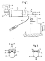
- movable arm 10 of a machine is movable (such movement being measured relative to a datum by transducers on the machine) relative to a table 12 in three dimensions, and the arm supports a female support member provided by a socket 14.
- the socket 14 is shown in more detail in Fig 2 and comprises a cylindrical cup 16 supporting three equi-spaced support elements provided by balls 18 in its inner rim.
- a magnet 20 is supported in the base of the cup 16, and the magnet 20 urges a male coupling member in the form of a spherical element 22 provided at one end of a telescopic bar 24 into engagement with the three balls 18.
- a foam pad 26 situated adjacent the balls 18 is impregnated with a suitable oil (e.g. a silicone based oil) to enable a continual supply of lubricant between the surfaces of the spherical element 22 and the balls 18.
- a suitable oil e.g. a silicone based oil
- the other end of the bar 24 is engaged with a male support member provided by a spherical element 28 for both universal pivotal motion and linear motion relative to the element 28.
- the mechanism enabling this movement is shown additionally in Fig 3 and comprises a pair of elongate parallel extending rods 30 and a leaf-spring 32 which urges the spherical element 28 into engagement with the rods 30.
- a pair of foam pads 34 are provided on the leaf-spring 32 which are impregnated with lubricant to provide continual lubrication between the surface of spherical element 28, the rods 30 and leaf-spring 32.
- a movable piston 36 is provided at the other end of the bar 24, and the piston 36 abuts the surface of the element 28.
- the piston 36 is part of a linear displacement transducer 38 provided inside the bar 24 which, when calibrated, determines the distance between the spherical elements 22 and 28.
- Linear displacement transducers are well known per se and will not be described further.
- the output of the transducer 38 is transmitted via a cable 60 to a processing device (not shown).
- the spherical element 28 is supported on the table 12 of the machine by a retaining device 40 which is itself supported in a workholder 42.
- the retaining device 40 permits movement in 3-dimensions of the spherical element 28 relative to the table 12 and can rigidly clamp the element 28 relative to the table 12.
- the retaining device 40 is shown in more detail in Figs 4 and 5 and comprises a clamping device having a pair of jaws 44 which enclose a cylindrical bore 46.
- the jaws 44 may be opened and closed by screw threaded engagement of a clamping bolt 48 with each of the jaws 44.
- the retaining device also includes a structure for supporting element 28 in clamping device.
- the spherical element 28 is supported on a carrying bar or stem 50, itself supported by a spherical carrying member 52 which lies inside of the bore 46.
- a spring 54 is provided within the bore 46 to urge the carrying member 52 out of the bore 46.
- the socket 14 is then disengaged from the spherical element 28 (the retaining device now preventing any movement of the element 28) and the bar 24 connected between the arm 10 and the table 12 as shown in Fig 1.
- the arm may thus then be driven in a circular path around the centre of the element 28 since the position of the centre has just been determined.
- a male support member i.e. the spherical element 28
- a female support member e.g. socket 14
- the retaining device 40 may be provided on the arm 10, with the male or female support member which is provided on the table 12 being rigidly supported thereto.
- the movable arm 110 e.g. the spindle
- the movable arm 110 carries a female coupling member provided by a magnetic socket 114, and is movable in 3-dimensions relative to a table 112.
- a male coupling member provided by a spherical reference element 128 is supported on the table 112 by a retaining device 140.
- the retaining device 140 is similar to the retaining device 40 described in the first embodiment, and has a clamping device operable by a clamping bolt 148 to retain a carrying member (not shown).
- the carrying member is connected to the carrying stem 150, which in turn supports spherical element 128.
- the retaining device 140 has a magnetic base and is thus magnetically retained on the table 112.
- the male and female support members 128,114 are interconnected by a transducer apparatus provided by a telescopic ball-bar 124.
- a male coupling member provided by spherical element 122, and situated at one end of the bar 124 is magnetically retained in the socket 114 to enable universal pivotal motion of the bar 124 relative to the arm 110.
- the other end of the ball-bar 124 has a female coupling member provided by a magnetic socket 130, in which the spherical element 128 is retained.
- a linear displacement transducer (not shown) provided within the ball-bar 124 determines (when calibrated) the spacing of the spherical elements 122,128. The output of the transducer is sent via a cable 160 to a computer in order to calibrate the machine.
- the ball-bar of this embodiment is set up and operated to calibrate the machine exactly as described with reference to the first embodiment of the present invention.
- FIGS 7 to 10 illustrate alternative forms of magnetic socket, which are used in conjunction with the ball-bar 124 of Fig 6.
- a socket 170 has a cup-shaped cylindrical body 172 having an axis A, in which a magnet 174 is retained.
- the body 172 supports three radially extending, and equi-spaced support elements, provided by ball-ended screws (made of a copper alloy such as phosphor-bronze) 176 in correspondingly screw-threaded bores.
- the spherical elements 122;128 are urged into the socket 170 by the magnet 174 and rest against the three areas of surface provided by the ball-ends of the screws 176.
- the position in which the spherical elements 122;128 are retained in the socket 170 may be adjusted by adjusting the radial displacement of the screws 176.
- a socket 180 comprises a cup-shaped cylindrical body 182 having an axis B and a permanent magnet 184 supported in the cup.
- the body 182 supports three axially extending copper alloy ball-ended screws 186 which are equi-spaced about axis B.
- the spherical elements 122;128 are urged into the socket 180 by the magnet 184 and are supported by three areas of surface provided by the ball-ends of the screws 186.
- the position of the spherical elements 122;128 within the socket 180 may be adjusted by adjusting the radial position of the screws 186.
- the screws 176;186 are retained in position by lock nuts 190 which lie in an enlarged portion 192 of the screw-threaded bore 194, and bear against a flat face 196 of the body 172;182 which surrounds the screws 176;186.
- the screws 176;186 are of phosphor bronze; advantages in wear may be obtained where the material from which the screws 176;186 are made has a substantially lower hardness than the material of the spherical elements 122;128. Also, the screws 176;186 do not have to be adjustable within the body 172;182; their position may be fixed. Nor is it essential for the screws to be equi-spaced, or for them to extend radially or axially provided that they support the spherical elements 122;128 in a stable position. Further, it is not essential for the ends of the screws 176,186 to be ball-ended, provided that the ends are such that the spherical elements are stably supported.
- the areas of surface for supporting the spherical elements 122;128 may be provided by a ring situated inside the rim of the body 172;182 of the socket.
- the ring may be of e.g. phosphor bronze of PTFE.
Landscapes
- Physics & Mathematics (AREA)
- General Physics & Mathematics (AREA)
- A Measuring Device Byusing Mechanical Method (AREA)
- Machine Tool Sensing Apparatuses (AREA)
- Machine Tool Units (AREA)
- Pivots And Pivotal Connections (AREA)
Claims (15)
- Vorrichtung zum Kalibrieren einer Koordinatenpositioniermaschine, wobei die Maschine einen Tisch (12; 112) und einen Arm (10; 110) aufweist, der relativ zum Tisch (12; 112) in wenigstens zwei Dimensionen bewegbar ist, und die Vorrichtung umfaßt: ein Stecker- und ein Buchsenstützglied (28; 128) bzw. (14; 114), die jeweils ausgelegt sind, auf entweder dem bewegbaren Arm (10, 110) oder dem Tisch (12; 112) gehalten zu sein, eine Transducervorrichtung mit einer länglichen Teleskopstange (24; 124), die ein Steckerkupplungsglied (22; 122) an dem einen Ende zum Bilden einer universellen Gelenkverbindung mit dem Buchsenstützglied (14; 114) und ein Buchsenkupplungsglied (30; 130) am anderen Ende zum Bilden einer universellen Gelenkverbindung mit dem Steckerstützglied (28; 128) aufweist, und Mittel zum Messen der Distanz zwischen den beiden Steckergliedern (22, 28; 122, 128),
dadurch gekennzeichnet,
daß Haltemittel (40; 140) für eines der Stützglieder (14, 28; 114, 128) vorgesehen sind, um einen Bereich einer 3-dimensionalen Bewegung relativ zu dem Teil der Maschine zu gestatten, auf welchem das eine Stützglied (14, 28; 114, 128) gehalten ist, und um starr und lösbar das eine Stützglied (14, 28; 114, 128) in einer fixierten Position innerhalb des Bereiches zu halten. - Vorrichtung nach Anspruch 1,
bei der das Steckerstützglied (22; 128) von einem sphärischen Referenzelement vorgesehen ist, und das Buchsenstützglied (14; 114) von einem Sockel für das sphärische Referenzelement vorgesehen ist. - Vorrichtung nach Anspruch 1 oder Anspruch 2,
bei der das Steckerkupplungsglied (22; 122) von einem sphärischen Referenzelement vorgesehen ist. - Vorrichtung nach einem der vorhergehenden Ansprüche,
bei der das Buchsenkupplungsglied (30; 130) von einem Sockel für ein sphärisches Referenzelement vorgesehen ist. - Vorrichtung nach Anspruch 4,
bei der jedes der Steckerglieder (22, 128; 122; 128) aus ferromagnetischem Material hergestellt ist und jeder der Sockel (14, 114; 130) drei Oberflächenbereiche (18; 176; 186) zum Stützen des Steckergliedes (22, 28; 122; 128), die jeweils aus einem Material mit einer geringeren Härte als das ferromagnetische Material hergestellt sind, und einen Magneten (20; 174; 184) umfaßt, um das Steckerglied (22, 28; 122, 128) in Kontakt mit den Oberflächenbereichen (18; 176; 186) zu drängen. - Vorrichtung nach Anspruch 5,
bei der jeder der Oberflächenbereiche (18; 176; 186) aus einer Kupferlegierung hergestellt ist. - Vorrichtung nach Anspruch 6,
bei der jeder der Oberflächenbereiche (18; 176; 186) aus Phosphorbronze hergestellt ist. - Vorrichtung nach einem der Ansprüche 5 bis 7,
bei der jeder der Oberflächenbereiche (18; 176; 186) von einem individuellen Stützelement (18; 176; 186) vorgesehen ist. - Vorrichtung nach Anspruch 8,
bei der jedes der Stützelemente von einer Schraube mit Kugelende (18; 176; 186) vorgesehen ist, deren Position relativ zum Körper des Sockels einstellbar ist. - Vorrichtung nach Anspruch 5,
bei der jeder der Oberflächenbereiche aus PTFE hergestellt ist. - Vorrichtung nach Anspruch 10,
bei der die Oberflächenbereiche von einem Ring vorgesehen sind. - Vorrichtung nach einem der Ansprüche 1 bis 3,
bei der das Buchsenkupplungsglied (30; 130) von einem Paar von Gabeln (30) vorgesehen ist, die sich parallel zur Länge der Stange (24; 124) erstrecken, wobei sich jede der Gabeln (30) im Gebrauch mit der Oberfläche des Steckerstützgliedes (28) in Eingriff befindet. - Vorrichtung nach Anspruch 1,
bei der das Haltemittel (40; 140) einen Trageschaft (50; 150), der an einem Ende mit dem Stützglied (28; 128) und am anderen Ende mit einem Trageglied (52) verbunden ist, und Klemmittel (44, 46, 48) umfaßt, um das Trageglied (52) starr an die Maschine zu klemmen und dadurch das Stützglied (28; 128) in der Position zu halten. - Vorrichtung nach Anspruch 13,
bei der das Trageglied (52) einen sphärischen Körper aufweist und das Klemmittel (44, 46, 48) eine zylindrische Bohrung (46), die von einem Paar von Backen (44) umschlossen ist, und Mittel (48) umfaßt, um die Backen zusammenzudrängen und dadurch das Trageglied (52) starr an die Basis zu klemmen. - Vorrichtung nach Anspruch 14,
bei der das Haltemittel (40; 140) am Tisch (12; 112) vorgesehen ist, und Vorspannmittel (54) vorgesehen sind, um das Trageglied (52) vom Tisch (12; 112) weg zu drängen.
Applications Claiming Priority (4)
| Application Number | Priority Date | Filing Date | Title |
|---|---|---|---|
| GB919107774A GB9107774D0 (en) | 1991-04-12 | 1991-04-12 | Calibration device |
| GB9107774 | 1991-04-12 | ||
| GB9113459 | 1991-06-21 | ||
| GB919113459A GB9113459D0 (en) | 1991-06-21 | 1991-06-21 | Magnetic coupling device |
Publications (3)
| Publication Number | Publication Date |
|---|---|
| EP0508686A2 EP0508686A2 (de) | 1992-10-14 |
| EP0508686A3 EP0508686A3 (en) | 1993-05-26 |
| EP0508686B1 true EP0508686B1 (de) | 1996-06-05 |
Family
ID=26298721
Family Applications (1)
| Application Number | Title | Priority Date | Filing Date |
|---|---|---|---|
| EP92302926A Expired - Lifetime EP0508686B1 (de) | 1991-04-12 | 1992-04-02 | Kalibriervorrichtung für Maschine |
Country Status (4)
| Country | Link |
|---|---|
| US (1) | US5214857A (de) |
| EP (1) | EP0508686B1 (de) |
| JP (1) | JPH0781804B2 (de) |
| DE (1) | DE69211210T2 (de) |
Cited By (1)
| Publication number | Priority date | Publication date | Assignee | Title |
|---|---|---|---|---|
| US6776551B2 (en) | 2000-09-29 | 2004-08-17 | Renishaw Plc | Retaining device |
Families Citing this family (38)
| Publication number | Priority date | Publication date | Assignee | Title |
|---|---|---|---|---|
| AT398246B (de) * | 1993-06-11 | 1994-10-25 | Frank Adolf Dipl Ing Dr | Vorrichtung zur kontrolle der geometrischen und dynamischen genauigkeit eines nc-gesteuerten arbeitskopfes |
| US5341574A (en) * | 1993-06-29 | 1994-08-30 | The United States Of America As Represented By The Department Of Energy | Coordinate measuring machine test standard apparatus and method |
| GB9401692D0 (en) | 1994-01-28 | 1994-03-23 | Renishaw Plc | Performing measurement or calibration on positioning machines |
| GB9406191D0 (en) * | 1994-03-29 | 1994-05-18 | Renishaw Plc | Mounting device for a telescopic ball-bar |
| US5533271A (en) * | 1994-08-23 | 1996-07-09 | Callaghan, Jr.; Robert P. | Long range sliding ball bar test gage |
| JP3292225B2 (ja) * | 1994-09-19 | 2002-06-17 | 株式会社安川電機 | 産業用ロボットの基準位置決め方法 |
| GB9425411D0 (en) * | 1994-12-16 | 1995-02-15 | Gen Electric Co Plc | Commodity consuption meters |
| DE19509403A1 (de) * | 1995-03-15 | 1996-09-19 | Dreier Lasermesstechnik Gmbh | Vorrichtung zur Überprüfung der Genauigkeit einer Kreisbahn einer Arbeitsspindel |
| US5647136A (en) * | 1995-07-10 | 1997-07-15 | Universities Research Association, Inc. | Automatic ball bar for a coordinate measuring machine |
| EP0896656A4 (de) * | 1995-11-14 | 2000-11-22 | Kam C Lau | Maschinenmontiertes ballstabsystem und verfahren zu dessen benutzung |
| GB9601679D0 (en) * | 1996-01-27 | 1996-03-27 | Renishaw Plc | Ball bar apparatus for calibrating a machine |
| KR100290298B1 (ko) | 1999-01-08 | 2001-05-15 | 김영삼 | 다축기계의 3차원입체오차 측정장치 |
| DE19915012A1 (de) * | 1999-04-01 | 2000-10-05 | Metronom Indvermessung Gmbh | Prüfkörper |
| US6810597B2 (en) * | 1999-04-08 | 2004-11-02 | Renishaw Plc | Use of surface measuring probes |
| GB9907868D0 (en) | 1999-04-08 | 1999-06-02 | Renishaw Plc | Method of calibrating a scanning system |
| US6317994B1 (en) * | 2000-03-03 | 2001-11-20 | Genesis Systems Group, Ltd. | Robot alignment apparatus and method for using same |
| DE10122200A1 (de) * | 2001-05-08 | 2002-11-14 | Zeiss Carl | Tastkopf für ein Koordinatenmeßgerät. Koordinatenmeßgerät, Kalibrierkörper für ein Koordinatenmeßgerät und Verfahren zum Kalibrieren eines Koordinatenmeßgerätes |
| US7040033B2 (en) * | 2001-10-05 | 2006-05-09 | Trustees Of Stevens Institute Of Technology | Six degrees of freedom precision measuring system |
| WO2004034164A1 (en) * | 2002-10-11 | 2004-04-22 | Fidia S.P.A. | System and process for measuring, compensating and testing numerically controlled machine tool heads and/or tables |
| US7245982B2 (en) * | 2002-10-11 | 2007-07-17 | Fidia S.P.A. | System and process for measuring, compensating and testing numerically controlled machine tool heads and/or tables |
| DE102006009422B4 (de) * | 2006-02-23 | 2011-08-18 | Dreier Lasermesstechnik GmbH, 72160 | Vorrichtung zur Überprüfung der Genauigkeit einer von einer Arbeitsspindel auszuführenden Kreisbahn |
| GB0608235D0 (en) | 2006-04-26 | 2006-06-07 | Renishaw Plc | Differential calibration |
| US7652275B2 (en) * | 2006-07-28 | 2010-01-26 | Mitutoyo Corporation | Non-contact probe control interface |
| US7508529B2 (en) * | 2006-07-31 | 2009-03-24 | Mitutoyo Corporation | Multi-range non-contact probe |
| CA2669878C (en) | 2006-11-20 | 2017-01-03 | Hexagon Metrology Ab | Coordinate measurement machine with improved joint |
| US7997001B1 (en) | 2010-06-14 | 2011-08-16 | King Fahd University Of Petroleum And Minerals | Telescopic ball bar gauge |
| JP5755017B2 (ja) * | 2011-04-28 | 2015-07-29 | オークマ株式会社 | 幾何誤差測定用球の保持機構 |
| US8602376B2 (en) | 2011-05-31 | 2013-12-10 | Nite Ize, Inc. | Multi-positional mount for personal electronic devices with a magnetic interface |
| US20190170291A1 (en) | 2011-05-31 | 2019-06-06 | Nite Ize, Inc. | Multi-positional mount for personal electronic devices with a magnetic interface |
| ES2769304T3 (es) * | 2012-04-05 | 2020-06-25 | Fidia Spa | Dispositivo para corrección de errores para máquinas CNC |
| KR101480229B1 (ko) * | 2013-06-12 | 2015-01-09 | 경북대학교 산학협력단 | 센터 마운트 및 그를 구비한 볼바 시스템 |
| GB201513850D0 (en) * | 2015-08-05 | 2015-09-16 | Renishaw Plc | Coordinate positioning machine |
| CN110860947B (zh) * | 2018-08-27 | 2022-04-08 | 成都飞机工业(集团)有限责任公司 | 一种定位找正的方法 |
| USD989754S1 (en) | 2020-10-20 | 2023-06-20 | Nite Ize, Inc. | Mobile device mount |
| USD975705S1 (en) | 2020-10-20 | 2023-01-17 | Nite Ize, Inc. | Device mount |
| US12047525B2 (en) | 2020-10-20 | 2024-07-23 | Nite Ize, Inc. | Squeeze device holder |
| US11516328B2 (en) | 2020-10-20 | 2022-11-29 | Nite Ize, Inc. | Systems and methods for an adjustable, quck release, positive pressure, electronic device holder |
| CN114234877B (zh) * | 2022-02-28 | 2022-06-14 | 成都飞机工业(集团)有限责任公司 | 一种用于R-test仪器的位移传感器矢量标定方法 |
Family Cites Families (13)
| Publication number | Priority date | Publication date | Assignee | Title |
|---|---|---|---|---|
| JPS5940581B2 (ja) * | 1979-09-07 | 1984-10-01 | 株式会社日立製作所 | はめあい装置 |
| US4435905A (en) * | 1982-03-15 | 1984-03-13 | The United States Of America As Represented By The United States Department Of Energy | Telescoping magnetic ball bar test gage |
| US4536962A (en) * | 1983-11-17 | 1985-08-27 | Applied Power Inc. | Datum point location apparatus |
| GB8411437D0 (en) * | 1984-05-04 | 1984-06-13 | Renishaw Plc | Co-ordinate positioning apparatus |
| JPS61209857A (ja) * | 1985-03-08 | 1986-09-18 | Yoshiaki Kakino | Nc工作機械の運動精度試験方法および装置 |
| JPS6279947A (ja) * | 1985-09-30 | 1987-04-13 | Yoshiaki Kakino | Nc工作機械の運動誤差補正方法及び装置 |
| GB2210978B (en) * | 1987-10-15 | 1991-06-05 | C D Measurements Limited | An accuracy testing device |
| DE3735075A1 (de) * | 1987-10-16 | 1989-04-27 | Zeiss Carl Fa | Pruefeinrichtung und verfahren zur bestimmung der messunsicherheit von koordinatenmessgeraeten |
| SE461548B (sv) * | 1988-02-18 | 1990-02-26 | Johansson Ab C E | Foerfarande och anordning foer bestaemning av och korrigering foer laegesfel vid maetning av en punkts laege eller vid positionering till en punkt med ett bestaemt laege |
| GB8812579D0 (en) * | 1988-05-27 | 1988-06-29 | Renishaw Plc | Test bar for position determination apparatus |
| JPH02159502A (ja) * | 1988-12-14 | 1990-06-19 | Toshiba Corp | 球体固定用治具 |
| GB8906287D0 (en) * | 1989-03-18 | 1989-05-04 | Renishaw Plc | Probe calibration |
| KR910005508B1 (ko) * | 1989-05-23 | 1991-07-31 | 박준호 | 컴퓨터 원용 키이니매틱 트랜듀서 링크 시스템 및 그 시스템을 사용한 nc 공작기계 정밀도의 측정 및 해석방법 |
-
1992
- 1992-04-02 EP EP92302926A patent/EP0508686B1/de not_active Expired - Lifetime
- 1992-04-02 DE DE69211210T patent/DE69211210T2/de not_active Expired - Lifetime
- 1992-04-06 US US07/864,338 patent/US5214857A/en not_active Expired - Lifetime
- 1992-04-13 JP JP4093059A patent/JPH0781804B2/ja not_active Expired - Lifetime
Cited By (1)
| Publication number | Priority date | Publication date | Assignee | Title |
|---|---|---|---|---|
| US6776551B2 (en) | 2000-09-29 | 2004-08-17 | Renishaw Plc | Retaining device |
Also Published As
| Publication number | Publication date |
|---|---|
| US5214857A (en) | 1993-06-01 |
| JPH0781804B2 (ja) | 1995-09-06 |
| DE69211210D1 (de) | 1996-07-11 |
| JPH05107003A (ja) | 1993-04-27 |
| EP0508686A3 (en) | 1993-05-26 |
| EP0508686A2 (de) | 1992-10-14 |
| DE69211210T2 (de) | 1996-10-10 |
Similar Documents
| Publication | Publication Date | Title |
|---|---|---|
| EP0508686B1 (de) | Kalibriervorrichtung für Maschine | |
| US5259120A (en) | Calibration and measurement device | |
| US4492036A (en) | Magnetic ball bar gauge | |
| CA1223465A (en) | Adjustable machining system and implement therefore | |
| KR101796842B1 (ko) | 구면 측정장치 | |
| WO2008067561A2 (en) | Interior contour measurement probe | |
| JPH0926458A (ja) | 自動テスト装置及び動的接点 | |
| US4414748A (en) | Ball mounting fixture for a roundness gage | |
| TWI808398B (zh) | 校正一坐標定位機器之方法 | |
| US3911586A (en) | Precision control apparatus | |
| JP2012047752A (ja) | 機械部品の寸法および/または形状の検査装置 | |
| WO2001051881A1 (en) | Measurement of geometric parameters of internal and external screw thread and similar grooves | |
| KR20100023387A (ko) | 내경구 측정 장치 | |
| US4796363A (en) | Means for supporting a gaging device such as a dial bore gage during the setting thereof | |
| Chetwynd | High-precision measurement of small balls | |
| US7111410B2 (en) | Centering device, in particular for a probe measuring device | |
| US5216818A (en) | Two-point internal diameter measurement gage | |
| CN210952770U (zh) | 一种检测锥外圆直径的装置 | |
| US6401348B1 (en) | Electrodynamic rotational axis acquisition tool | |
| US4991306A (en) | Tactile center locator | |
| CN118111329A (zh) | 一种测量精密小型主轴内锥跳动的检具 | |
| US5201131A (en) | Coordinate measuring machine | |
| CN216523574U (zh) | 一种检测量具 | |
| US2952918A (en) | Gauging device | |
| US1954233A (en) | Gauge for testing cylindrical objects |
Legal Events
| Date | Code | Title | Description |
|---|---|---|---|
| PUAI | Public reference made under article 153(3) epc to a published international application that has entered the european phase |
Free format text: ORIGINAL CODE: 0009012 |
|
| AK | Designated contracting states |
Kind code of ref document: A2 Designated state(s): CH DE FR GB IT LI SE |
|
| PUAL | Search report despatched |
Free format text: ORIGINAL CODE: 0009013 |
|
| AK | Designated contracting states |
Kind code of ref document: A3 Designated state(s): CH DE FR GB IT LI SE |
|
| 17P | Request for examination filed |
Effective date: 19931106 |
|
| 17Q | First examination report despatched |
Effective date: 19941202 |
|
| GRAH | Despatch of communication of intention to grant a patent |
Free format text: ORIGINAL CODE: EPIDOS IGRA |
|
| GRAH | Despatch of communication of intention to grant a patent |
Free format text: ORIGINAL CODE: EPIDOS IGRA |
|
| GRAA | (expected) grant |
Free format text: ORIGINAL CODE: 0009210 |
|
| ITF | It: translation for a ep patent filed | ||
| AK | Designated contracting states |
Kind code of ref document: B1 Designated state(s): CH DE FR GB IT LI SE |
|
| REF | Corresponds to: |
Ref document number: 69211210 Country of ref document: DE Date of ref document: 19960711 |
|
| PG25 | Lapsed in a contracting state [announced via postgrant information from national office to epo] |
Ref country code: SE Effective date: 19960905 |
|
| ET | Fr: translation filed | ||
| PLBE | No opposition filed within time limit |
Free format text: ORIGINAL CODE: 0009261 |
|
| STAA | Information on the status of an ep patent application or granted ep patent |
Free format text: STATUS: NO OPPOSITION FILED WITHIN TIME LIMIT |
|
| 26N | No opposition filed | ||
| PGFP | Annual fee paid to national office [announced via postgrant information from national office to epo] |
Ref country code: FR Payment date: 19980312 Year of fee payment: 7 |
|
| PGFP | Annual fee paid to national office [announced via postgrant information from national office to epo] |
Ref country code: CH Payment date: 19980403 Year of fee payment: 7 |
|
| PG25 | Lapsed in a contracting state [announced via postgrant information from national office to epo] |
Ref country code: LI Free format text: LAPSE BECAUSE OF NON-PAYMENT OF DUE FEES Effective date: 19990430 Ref country code: CH Free format text: LAPSE BECAUSE OF NON-PAYMENT OF DUE FEES Effective date: 19990430 |
|
| REG | Reference to a national code |
Ref country code: CH Ref legal event code: PL |
|
| PG25 | Lapsed in a contracting state [announced via postgrant information from national office to epo] |
Ref country code: FR Free format text: LAPSE BECAUSE OF NON-PAYMENT OF DUE FEES Effective date: 19991231 |
|
| REG | Reference to a national code |
Ref country code: FR Ref legal event code: ST |
|
| REG | Reference to a national code |
Ref country code: GB Ref legal event code: IF02 |
|
| PG25 | Lapsed in a contracting state [announced via postgrant information from national office to epo] |
Ref country code: IT Free format text: LAPSE BECAUSE OF NON-PAYMENT OF DUE FEES Effective date: 20050402 |
|
| PGFP | Annual fee paid to national office [announced via postgrant information from national office to epo] |
Ref country code: DE Payment date: 20110421 Year of fee payment: 20 |
|
| PGFP | Annual fee paid to national office [announced via postgrant information from national office to epo] |
Ref country code: GB Payment date: 20110421 Year of fee payment: 20 |
|
| REG | Reference to a national code |
Ref country code: DE Ref legal event code: R071 Ref document number: 69211210 Country of ref document: DE |
|
| REG | Reference to a national code |
Ref country code: DE Ref legal event code: R071 Ref document number: 69211210 Country of ref document: DE |
|
| REG | Reference to a national code |
Ref country code: GB Ref legal event code: PE20 Expiry date: 20120401 |
|
| PG25 | Lapsed in a contracting state [announced via postgrant information from national office to epo] |
Ref country code: GB Free format text: LAPSE BECAUSE OF EXPIRATION OF PROTECTION Effective date: 20120401 |
|
| PG25 | Lapsed in a contracting state [announced via postgrant information from national office to epo] |
Ref country code: DE Free format text: LAPSE BECAUSE OF EXPIRATION OF PROTECTION Effective date: 20120403 |