EP0508339A2 - Dispositif de mesure sans contact pour déterminer le contour d'objects longitudinaux aux surfaces réfléchissantes diffusives - Google Patents
Dispositif de mesure sans contact pour déterminer le contour d'objects longitudinaux aux surfaces réfléchissantes diffusives Download PDFInfo
- Publication number
- EP0508339A2 EP0508339A2 EP92105868A EP92105868A EP0508339A2 EP 0508339 A2 EP0508339 A2 EP 0508339A2 EP 92105868 A EP92105868 A EP 92105868A EP 92105868 A EP92105868 A EP 92105868A EP 0508339 A2 EP0508339 A2 EP 0508339A2
- Authority
- EP
- European Patent Office
- Prior art keywords
- measuring
- measurement object
- measuring system
- measurement
- plane
- Prior art date
- Legal status (The legal status is an assumption and is not a legal conclusion. Google has not performed a legal analysis and makes no representation as to the accuracy of the status listed.)
- Granted
Links
- 238000005259 measurement Methods 0.000 claims abstract description 32
- 230000005855 radiation Effects 0.000 claims abstract description 21
- 230000003287 optical effect Effects 0.000 claims description 10
- 238000011156 evaluation Methods 0.000 claims description 6
- 238000010191 image analysis Methods 0.000 claims description 3
- 238000001514 detection method Methods 0.000 claims description 2
- 230000005693 optoelectronics Effects 0.000 abstract description 2
- 239000000523 sample Substances 0.000 description 9
- 238000000034 method Methods 0.000 description 6
- 101100008050 Caenorhabditis elegans cut-6 gene Proteins 0.000 description 2
- 238000012545 processing Methods 0.000 description 2
- 241000283690 Bos taurus Species 0.000 description 1
- 238000011161 development Methods 0.000 description 1
- 230000018109 developmental process Effects 0.000 description 1
- 238000006073 displacement reaction Methods 0.000 description 1
- 238000003384 imaging method Methods 0.000 description 1
- 238000004519 manufacturing process Methods 0.000 description 1
- 238000011895 specific detection Methods 0.000 description 1
- 230000007704 transition Effects 0.000 description 1
- 238000009966 trimming Methods 0.000 description 1
- 239000002699 waste material Substances 0.000 description 1
Images


Classifications
-
- G—PHYSICS
- G01—MEASURING; TESTING
- G01B—MEASURING LENGTH, THICKNESS OR SIMILAR LINEAR DIMENSIONS; MEASURING ANGLES; MEASURING AREAS; MEASURING IRREGULARITIES OF SURFACES OR CONTOURS
- G01B11/00—Measuring arrangements characterised by the use of optical techniques
- G01B11/02—Measuring arrangements characterised by the use of optical techniques for measuring length, width or thickness
- G01B11/024—Measuring arrangements characterised by the use of optical techniques for measuring length, width or thickness by means of diode-array scanning
Definitions
- the invention relates to a measuring system for the contactless detection of long objects with a diffusely reflecting surface, in particular for use in sawmills to cut sharp-edged boards from side goods.
- a number of optical coordinate measuring machines are known for non-contact measurement.
- the basic principle here is to be seen in the fact that the procedure is as in known electro-mechanical touch probes, in that the workpiece geometry is carried out by coordinate-specific detection of individual points on the surface of the workpiece. However, the surface is touched optically, ie without contact.
- there are different methods e.g. B. that of interference, diffraction, triangulation, image analysis and others.
- DE-OS 29 03 529 and DE-OS 21 13 522 describe a method for the contactless measurement of objects, in which the optical scanning of workpieces is carried out according to the triangulation principle.
- a light spot is projected onto the measurement object at an angle and the distance between the radiation source and the measurement object is determined from the displacement of the image of the light spot measured with a position-sensitive detector.
- a desired further evaluation and processing of the determined value is then carried out with the aid of an image analysis device assigned to the detector.
- the projector and the imaging system are combined as a so-called optical probe to form an assembly.
- the object distance can only be determined without error if the angle that the object surface forms with the axes of the probe does not change, or if the probe follows the workpiece so that the image of the projected light spot is always in the center of the detector appears.
- the measuring speed depends not only on the electronic but also on the mechanical structure, i. H. it is affected by the latter.
- the probe can be adjusted for different angular positions via a locking device.
- a constant new angle adjustment would be required, which in turn requires a high level of mechanical effort.
- sawmills already have a cost-effective method with laser scanning systems for measuring board goods to be trimmed during longitudinal conveying.
- the board goods are measured behind a feed table using a row of sensors.
- measuring and sawing are serial processes, additional space is required in accordance with the length of the board to be processed. Small sawmills often do not have this space requirement.
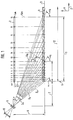
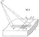
- FIG. 1 shows the concept of the measuring system with its light sections and beam paths. The entire further description is based on the representation for measuring board goods 1, so that maximum use can be made during trimming. Of course, the system is also suitable for determining the contours of other long and flat objects.
- the light section 5.1 of the first radiation source 4.1 represents the reference point 6 for the zero section.
- a lens 9 of a CCD line camera 10 is arranged above the reference plane 3 at a distance (1) 7 and at a height (h) 8.
- the measuring section 11 is limited by the number of light sections 5.m.
- the entire measuring length 12 can, however, extend beyond this measuring section 11 if it is ensured that the beginning of the board goods 1 is at the zero cut 6.
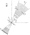
- FIG. 2 shows a detailed illustration of the CCD line 10 according to FIG. 1 and its beam paths through the objective 9.
- the pixels from 0 to 2048 are recorded in the CCD line, a different number of pixels is of course also possible.
- a central beam path serves as the optical axis 13. The entire beam area is covered by the object field angle 2 ⁇ .
- the angle between two beam paths is called the field angle ⁇ m for the measuring points.
- a further angle ⁇ is formed from the optical axis 13 to the vertical.
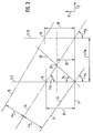
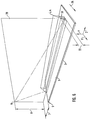
- FIG. 1 A section of two measuring points according to FIG. 1 is shown in FIG.
- the reference plane 3 and the cutouts are shown for the two light sections 5.9 and 5.10, ie for the 9th and 10th radiation sources 4.9, 4.10.
- the light section of the 9th radiation source 4.9 meets together with the optical axis 13 on the reference plane 3.
- the angle which the optical axis 13 forms with the light section is designated ⁇ 9.
- This means that the optical axis 13 is the reflected beam of the light section 5.9, which is detected by the detector.
- the reflected beam of the light section 5.10 intersects the light section 5.9 at point 16.
- the distance from point 16 to the reference plane 3 represents the possible measuring range height 17 at this point.
- the reflected beam 15 of the light section 5.11 intersects the light section 5.10 at point 18.
- the Distance of the point 18 from the reference plane 3 represents the measuring range height 19 which is possible at this point.
- a further light section 20 is shown over an angle ⁇ 9. Expressed by the angle ⁇ 9, this light section 20 exhibits an inclination which is possible for the light sections 5.m in order to enable a more precise measurement.
- the intersection 21 of this light section 20 with the reflected beam 14 of the light section 5.10 represents the maximum measuring range height 22.
- the distance between the two light sections 5.9, 5.10 is referred to in this case with ⁇ zm.
- FIG. 4 shows a representation of the object field of the CCD line camera on the board surface.
- the object field 23 of the CCD line camera 10 can be seen in the top view of the board product 1.
- the lens 9 of the CCD line camera 10 is arranged at a distance 7 from the zero cut 6 of the board product 1.
- the radiation sources 4.m are located at a short distance above the board goods 1.
- the board feed direction 25 runs from the reference plane 3 in the X direction.
- FIG. 1 A light section with the surface of a pixel is now shown in FIG.
- the radiation source 4.m located off-center of the object field 23 throws its rays in a certain width 28 onto the surface of the board goods 1.
- the object field 23 is delimited by its object field boundaries 26, 27.
- the intersection 28 of the beam path of the radiation source 4.m with the object field 23 results in the part of the area conjugated to the surface 29 of a pixel that is irradiated.
- the lens 9 of the CCD line camera 10 lies at a distance 7 and at a height 8 from the zero cut.
- This CCD line camera has an observation plane 30 which has been shown overall.
- This observation plane 30 perpendicularly meets the light sections 5m formed by the radiation sources 4.m, which have a triangular shape when viewed in the direction of the reference plane.
- the observation plane 30 now strikes approximately in the middle of these fan beams formed by the radiation sources 4.m.
- the intersection 31 forms the maximum height 22 of the board goods 1 to be measured.
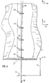
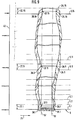
- FIG. 7 shows a possible measurement object with the measurement points recorded.
- a section of the board goods 1 is sufficient, which is guided in the board feed direction 25, into the intersection points of the light sections 5.m and the object field 23.
- a measuring point 35.m, 35.m + 1 is stored in an evaluation unit (not shown). The same applies when the upper edge of the forest edge 32 is reached. Then the measuring points 36.m, 36.m + 1 are saved.
- a third measuring point 37.m, 37.m + 1 is stored. The last measuring point 38.m, 38.m + 1 is saved when the lower edge leaves the intersection of the light rays.
- Figure 8 the associated section of a measurement is shown again individually. Seen from the feed direction 25, the first measuring point 35.m is detected on the lower edge of the forest edge 32. The next measuring point 36.m to be stored is detected when the upper edge of the board is reached. As soon as the upper edge of the second forest edge 32 passes through the observation plane 30 of the CCD line camera 10, the third measurement point 37.m is recorded. Ultimately, the fourth measuring point 38.m is stored when the lower edge of the board goods 1 leaves the observation plane 30. This result is achieved by serial evaluation of the CCD line signals at constant time or path intervals.
- FIG. 9 shows a representation of the curves of the pixels per measuring point in connection with the CCD line signal.
- the starting point is again a board product 1 which is moved in the direction of movement 25.
- the light sections are assigned to the individual pixel numbers 39.
- Selected measurement curves are shown for light sections 5.1, 5.9 and 5.16.
- the possible measuring height 22.1, 22.9 or 22.16 corresponds to the distance between the pixels.
- the CCD line signals 40 are still assigned. If the individual measuring points 36.m or 37.m of the upper edges of the side goods are now considered, it can be seen that straight cuts 51, 52 can be made so that all forest edge pieces fall out.
- FIG. 10 shows a possible use of the measuring arrangement in a sawmill.
- Woodworking in a sawmill begins with a pre-cutting machine, usually a gate, behind which the main and side goods are separated. After separating the main and side goods, the side goods are cut to the appropriate length and the rinds are sorted out.
- Sharp-edged boards must be cut from the side goods on at least one cut surface, ie the forest edge or part of it must be cut off. These boards are cut in a trimmer.
- the trimmer generally consists of several adjustable saws, which are positioned so that the optimal board is sawn with maximum use of side goods. Since the boards can have any width and can also be curved as desired, each board must be aligned when inserted into the trimmer.
- the side goods are transported on a cross conveyor 42 via a separator 50 and a waste chute 41, which removes rejects. Appropriate transport devices of the cross conveyor 42 bring the board goods 1 to the measuring table 43 arranged on the cross conveyor 42.
- the CCD line camera 10 is arranged above this measuring table 43.
- the corresponding radiation sources 4.m are also arranged above this table.
- the measured board 44 is then possibly brought to a waiting position 45.
- the board is then transported to a feed table 47 by means of a positioner 46 or directly through the cross conveyor 42.
- Alignment cylinders 48 are arranged on this feed table 47, which align the measured board in accordance with the evaluated measuring points.
- the board 44 is aligned, it is fixed on the feed table 47 by pressure rollers 49.
- the board is then sawn by pushing it through an arrangement of saws, not shown.
- the saw blade setting is calculated from the control signals, which result from the board width, by means of an evaluation unit, also not shown.
- the center line of the board to be cut is called the ideal line and must be aligned with the saw setting.
- Alignment takes place on the trimmer feed table.
- the alignment unit i. H. the alignment cylinders 48 consist, for example, of a retractable stop which is equipped with defined extendable pistons.
- the pistons are positioned so that they lie on the same board length as the measuring points.
- two pistons are positioned so that the board is automatically aligned when they are placed against these pistons.
- the distance between the ideal forest line and the forest edge is calculated to control the pistons.
- the alignment pistons are mounted on a retractable stop. As soon as the board is aligned and fixed, the pistons are sunk and the board is inserted into the trimmer.
Landscapes
- Physics & Mathematics (AREA)
- General Physics & Mathematics (AREA)
- Length Measuring Devices By Optical Means (AREA)
Applications Claiming Priority (2)
| Application Number | Priority Date | Filing Date | Title |
|---|---|---|---|
| DE4112009A DE4112009A1 (de) | 1991-04-12 | 1991-04-12 | Messsystem zur beruehrungslosen erfassung der kontur von langgegenstaenden mit diffus reflektierender oberflaeche |
| DE4112009 | 1991-04-12 |
Publications (3)
| Publication Number | Publication Date |
|---|---|
| EP0508339A2 true EP0508339A2 (fr) | 1992-10-14 |
| EP0508339A3 EP0508339A3 (en) | 1993-04-21 |
| EP0508339B1 EP0508339B1 (fr) | 1995-07-05 |
Family
ID=6429478
Family Applications (1)
| Application Number | Title | Priority Date | Filing Date |
|---|---|---|---|
| EP92105868A Expired - Lifetime EP0508339B1 (fr) | 1991-04-12 | 1992-04-04 | Dispositif de mesure sans contact pour déterminer le contour d'objects longitudinaux aux surfaces réfléchissantes diffusives |
Country Status (4)
| Country | Link |
|---|---|
| EP (1) | EP0508339B1 (fr) |
| CA (1) | CA2065775A1 (fr) |
| DE (2) | DE4112009A1 (fr) |
| FI (1) | FI921569A (fr) |
Cited By (1)
| Publication number | Priority date | Publication date | Assignee | Title |
|---|---|---|---|---|
| EP0608634A2 (fr) * | 1993-01-12 | 1994-08-03 | Kabushiki Kaisha Toshiba | Dispositif pour mesurer la forme d'une surface |
Families Citing this family (1)
| Publication number | Priority date | Publication date | Assignee | Title |
|---|---|---|---|---|
| DE102010021951A1 (de) * | 2010-05-28 | 2011-12-01 | Weber Maschinenbau Gmbh Breidenbach | Abtasteinrichtung |
Citations (2)
| Publication number | Priority date | Publication date | Assignee | Title |
|---|---|---|---|---|
| EP0007079A1 (fr) * | 1978-07-10 | 1980-01-23 | Saab-Scania Aktiebolag | Méthode et dispositif pour explorer et mesurer des pièces longues irrégulières telles que des planches |
| EP0145957A1 (fr) * | 1983-11-25 | 1985-06-26 | Firma Carl Zeiss | Procédé et appareil de mesure à distance d'objets |
Family Cites Families (5)
| Publication number | Priority date | Publication date | Assignee | Title |
|---|---|---|---|---|
| DE2113522C3 (de) * | 1971-03-19 | 1974-05-09 | Siemens Ag | Verfahren zuna berühningsfreien Messen eines Oberflächenprofils |
| US3787700A (en) * | 1971-07-27 | 1974-01-22 | Atmospheric Sciences Inc | Automatic system for measuring selected dimensions |
| DE2903529A1 (de) * | 1979-01-31 | 1980-08-07 | Schlatter Ag | Verfahren zum messen von entfernungen und vorrichtung zur durchfuehrung des verfahrens |
| DE3817387A1 (de) * | 1988-05-19 | 1989-11-30 | Mannesmann Ag | Verfahren und vorrichtung zur erfassung der aeusseren gestalt eines langgestreckten, im querschnitt prismatischen koerpers |
| US4943157A (en) * | 1989-05-18 | 1990-07-24 | Corning Incorporated | Fiber optic triangulation gage |
-
1991
- 1991-04-12 DE DE4112009A patent/DE4112009A1/de active Granted
-
1992
- 1992-04-04 EP EP92105868A patent/EP0508339B1/fr not_active Expired - Lifetime
- 1992-04-04 DE DE59202777T patent/DE59202777D1/de not_active Expired - Fee Related
- 1992-04-09 FI FI921569A patent/FI921569A/fi not_active Application Discontinuation
- 1992-04-10 CA CA002065775A patent/CA2065775A1/fr not_active Abandoned
Patent Citations (2)
| Publication number | Priority date | Publication date | Assignee | Title |
|---|---|---|---|---|
| EP0007079A1 (fr) * | 1978-07-10 | 1980-01-23 | Saab-Scania Aktiebolag | Méthode et dispositif pour explorer et mesurer des pièces longues irrégulières telles que des planches |
| EP0145957A1 (fr) * | 1983-11-25 | 1985-06-26 | Firma Carl Zeiss | Procédé et appareil de mesure à distance d'objets |
Cited By (2)
| Publication number | Priority date | Publication date | Assignee | Title |
|---|---|---|---|---|
| EP0608634A2 (fr) * | 1993-01-12 | 1994-08-03 | Kabushiki Kaisha Toshiba | Dispositif pour mesurer la forme d'une surface |
| EP0608634A3 (en) * | 1993-01-12 | 1995-09-06 | Toshiba Kk | Surface shape measurement device. |
Also Published As
| Publication number | Publication date |
|---|---|
| CA2065775A1 (fr) | 1992-10-13 |
| EP0508339B1 (fr) | 1995-07-05 |
| FI921569A0 (fi) | 1992-04-09 |
| DE4112009C2 (fr) | 1993-07-15 |
| FI921569A (fi) | 1992-10-13 |
| EP0508339A3 (en) | 1993-04-21 |
| DE59202777D1 (de) | 1995-08-10 |
| DE4112009A1 (de) | 1992-10-22 |
Similar Documents
| Publication | Publication Date | Title |
|---|---|---|
| DE69517349T2 (de) | Lichtscanner mit ineinander greifenden Kamerafeldern und parallellen Lichtbündeln | |
| EP0913707B1 (fr) | Procédé pour mesurer sans contact la distance d'un objet selon le principe de triangulation à laser | |
| DE68902329T2 (de) | Verfahren und apparat zur ueberwachung des oberflaechenprofils eines werkstueckes. | |
| DE3515194C2 (fr) | ||
| DE69632468T2 (de) | Verfahren zur Volumenmessung eines Gegenstandes mittels eines Laserabtasters und eines CCD Bildsensors | |
| DE3926349C2 (fr) | ||
| DE3309584A1 (de) | Optisches inspektionssystem | |
| DE3036257A1 (de) | Vorrichtung zur elektro-optischen abstandsmessung | |
| DE3445830A1 (de) | Foerderanlage mit positioniervorrichtung | |
| DE2555975C3 (de) | Einrichtung zur Bestimmung bzw. Überwachung der Abmessung insbesondere des Volumens eines bewegten Gegenstandes | |
| DE3805455C2 (fr) | ||
| DE2532603A1 (de) | Optische vorrichtung zur bestimmung des lichtaustrittswinkel | |
| EP1041394B1 (fr) | Dispositif opto-électronique | |
| DE2727926C3 (de) | Vorrichtung zur Ermittlung von Fehlstellen auf der reflektierenden Oberfläche einer Bahn | |
| DE69806994T2 (de) | Vorrichtung zum Messen der Dimensionen eines langgestreckten Objektes mit einer im Durchschnitt gekrümmten Kontur | |
| DE69629482T2 (de) | Verfahren und Apparat zur Volumenmessung eines Gegenstandes mittels eines Laserabtasters | |
| EP0508339B1 (fr) | Dispositif de mesure sans contact pour déterminer le contour d'objects longitudinaux aux surfaces réfléchissantes diffusives | |
| DE3612036C2 (fr) | ||
| DE3017672A1 (de) | Vorrichtung und verfahren zum nachweis von loechern in platten-, blatt- oder folienmaterial | |
| DE102008010965B4 (de) | Roboter-Bahnführung | |
| EP3575741B1 (fr) | Procédé de mesure sans contact d'un bord de pièce à usiner | |
| DE3702691A1 (de) | Beruehrungsloser abstandssensor | |
| DE2928085C2 (de) | Vorrichtung zur Breitenvermessung von baumrandigen Brettern unterschiedlicher Dicke | |
| DE19616708A1 (de) | Vorrichtung zur Vermessung und Sortierung von Werkstücken | |
| DE3732880C1 (de) | Verfahren zum Nachfuehren eines Elektronenstrahls entlang der Stossfuge zweier zu verschweissender Werkstuecke beim Elektronenstrahlschweissen |
Legal Events
| Date | Code | Title | Description |
|---|---|---|---|
| PUAI | Public reference made under article 153(3) epc to a published international application that has entered the european phase |
Free format text: ORIGINAL CODE: 0009012 |
|
| AK | Designated contracting states |
Kind code of ref document: A2 Designated state(s): DE ES FR IT SE |
|
| PUAL | Search report despatched |
Free format text: ORIGINAL CODE: 0009013 |
|
| AK | Designated contracting states |
Kind code of ref document: A3 Designated state(s): DE ES FR IT SE |
|
| 17P | Request for examination filed |
Effective date: 19930428 |
|
| RAP1 | Party data changed (applicant data changed or rights of an application transferred) |
Owner name: AUTRONIC GESELLSCHAFT FUER BILDVERARBEITUNG UND SY |
|
| 17Q | First examination report despatched |
Effective date: 19940609 |
|
| GRAA | (expected) grant |
Free format text: ORIGINAL CODE: 0009210 |
|
| AK | Designated contracting states |
Kind code of ref document: B1 Designated state(s): DE ES FR IT SE |
|
| PG25 | Lapsed in a contracting state [announced via postgrant information from national office to epo] |
Ref country code: ES Free format text: THE PATENT HAS BEEN ANNULLED BY A DECISION OF A NATIONAL AUTHORITY Effective date: 19950705 |
|
| REF | Corresponds to: |
Ref document number: 59202777 Country of ref document: DE Date of ref document: 19950810 |
|
| ITF | It: translation for a ep patent filed | ||
| ET | Fr: translation filed | ||
| PLBE | No opposition filed within time limit |
Free format text: ORIGINAL CODE: 0009261 |
|
| STAA | Information on the status of an ep patent application or granted ep patent |
Free format text: STATUS: NO OPPOSITION FILED WITHIN TIME LIMIT |
|
| 26N | No opposition filed | ||
| PGFP | Annual fee paid to national office [announced via postgrant information from national office to epo] |
Ref country code: FR Payment date: 19970328 Year of fee payment: 6 |
|
| PGFP | Annual fee paid to national office [announced via postgrant information from national office to epo] |
Ref country code: SE Payment date: 19970429 Year of fee payment: 6 |
|
| PGFP | Annual fee paid to national office [announced via postgrant information from national office to epo] |
Ref country code: DE Payment date: 19970624 Year of fee payment: 6 |
|
| PG25 | Lapsed in a contracting state [announced via postgrant information from national office to epo] |
Ref country code: SE Free format text: LAPSE BECAUSE OF NON-PAYMENT OF DUE FEES Effective date: 19980405 |
|
| PG25 | Lapsed in a contracting state [announced via postgrant information from national office to epo] |
Ref country code: FR Free format text: THE PATENT HAS BEEN ANNULLED BY A DECISION OF A NATIONAL AUTHORITY Effective date: 19980430 |
|
| EUG | Se: european patent has lapsed |
Ref document number: 92105868.1 |
|
| PG25 | Lapsed in a contracting state [announced via postgrant information from national office to epo] |
Ref country code: DE Free format text: LAPSE BECAUSE OF NON-PAYMENT OF DUE FEES Effective date: 19990202 |
|
| REG | Reference to a national code |
Ref country code: FR Ref legal event code: ST |
|
| PG25 | Lapsed in a contracting state [announced via postgrant information from national office to epo] |
Ref country code: IT Free format text: LAPSE BECAUSE OF NON-PAYMENT OF DUE FEES Effective date: 20050404 |