EP0507993B1 - Vorrichtung zum Öffnen und Schliessen von mehreren Flügeln durch kombiniertes Schwenken und Schieben von denselben - Google Patents
Vorrichtung zum Öffnen und Schliessen von mehreren Flügeln durch kombiniertes Schwenken und Schieben von denselben Download PDFInfo
- Publication number
- EP0507993B1 EP0507993B1 EP91120744A EP91120744A EP0507993B1 EP 0507993 B1 EP0507993 B1 EP 0507993B1 EP 91120744 A EP91120744 A EP 91120744A EP 91120744 A EP91120744 A EP 91120744A EP 0507993 B1 EP0507993 B1 EP 0507993B1
- Authority
- EP
- European Patent Office
- Prior art keywords
- wings
- wing
- adjacent
- gear wheels
- pair
- Prior art date
- Legal status (The legal status is an assumption and is not a legal conclusion. Google has not performed a legal analysis and makes no representation as to the accuracy of the status listed.)
- Expired - Lifetime
Links
- 238000005192 partition Methods 0.000 description 2
- 230000007246 mechanism Effects 0.000 description 1
Images

Classifications
-
- E—FIXED CONSTRUCTIONS
- E05—LOCKS; KEYS; WINDOW OR DOOR FITTINGS; SAFES
- E05D—HINGES OR SUSPENSION DEVICES FOR DOORS, WINDOWS OR WINGS
- E05D15/00—Suspension arrangements for wings
- E05D15/26—Suspension arrangements for wings for folding wings
-
- E—FIXED CONSTRUCTIONS
- E05—LOCKS; KEYS; WINDOW OR DOOR FITTINGS; SAFES
- E05D—HINGES OR SUSPENSION DEVICES FOR DOORS, WINDOWS OR WINGS
- E05D3/00—Hinges with pins
- E05D3/06—Hinges with pins with two or more pins
- E05D3/12—Hinges with pins with two or more pins with two parallel pins and one arm
- E05D3/122—Gear hinges
-
- E—FIXED CONSTRUCTIONS
- E05—LOCKS; KEYS; WINDOW OR DOOR FITTINGS; SAFES
- E05Y—INDEXING SCHEME ASSOCIATED WITH SUBCLASSES E05D AND E05F, RELATING TO CONSTRUCTION ELEMENTS, ELECTRIC CONTROL, POWER SUPPLY, POWER SIGNAL OR TRANSMISSION, USER INTERFACES, MOUNTING OR COUPLING, DETAILS, ACCESSORIES, AUXILIARY OPERATIONS NOT OTHERWISE PROVIDED FOR, APPLICATION THEREOF
- E05Y2900/00—Application of doors, windows, wings or fittings thereof
- E05Y2900/20—Application of doors, windows, wings or fittings thereof for furniture, e.g. cabinets
Definitions
- This invention relates to a device capable of causing a plurality of wing elements to open and close through combined swinging and sliding movements thereof, these wing elements being generally of the type as used in the furnishings art, for example, for constructing the front wall of a cabinet, a partition, etc..
- the wings are commonly pair-arranged with the wings of each pair of wings being able to be opened like a "book”, that is to say, to be superposed upon each other and then moved together to one side or the other.
- US-A-3,344,837 describes a folding panel assembly according to the preamble of claim 1, which may be used in an opening in a structure, in particular as a door for a garage, and which is movable vertically between an extended, lower position and a retracted or stacked upper position.
- gear wheels and associated complex mechanisms are provided for moving together the panels, which, however, can be brought only to the upper end of the opening in the stacked position.
- a hinge device is arranged between the different wings in an alternate manner, the hinge device being able to convert the swinging movement of a wing into a swinging movement equal but opposed in direction of an adjacent wing, thereby to achieve sliding movement of all of the wings in a same direction.
- this device includes a pair of gear wheels constantly in mesh with one another, supported, for example, by the guide and support head rail of the wings, these gear wheels having each an arm associated thereto, which arm is slidingly guided into a corresponding wing.
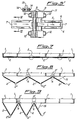
- Figures 1 to 3 are schematic views of the front part of a cabinet which is shown to have vertical walls 1 with the inside space being closed at its front by an even number of wings 2, in particular four wings 2.
- the above example is merely an illustrative example and that the wings 2 could both be different in number -for example 6 in number - and serve for a different purpose from that shown, for example, they may be used for constructing a partition.
- the wings 2 are pair-arranged so that the wings in each pair of wings can be superposed upon one another through combined swinging and sliding movements thereof. Accordingly, the remote ends 2' of the wings of each pair of wings are supported and guided between two rails, namely a top and a bottom rail (not shown) as usually provided for enabling the wings to slide, while the adjacent ends of wings in each pair of wings are hinged to one another to permit the wings to open and close"as a book", in a conventional manner.
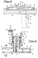
- the ends 2' of adjacent pairs of wings are connected together, as at the encircled locations A in figures 1 to 3, by the aid of a hinge device shown in figures 4 and 5 or 5', which device enables all of the wings to be opened and closed simultaneously, in a manner to keep them parallel two by two, and to cause all of them to slidingly move to a side, by action upon one of the two terminal wings, as schematically shown figure 2 and 3.
- This hinge device shown in figures 4 and 5 or 5', is generally indicated by reference numeral 3 and substantially comprises a pair of gear wheels 4 in constant mesh with one another, each gear wheel having integrally connected to it an arm 5 carrying a pair of rollers 6 at the free end of the arm, the rollers 6 being arranged to roll in an associated C-shaped guide member 7 (see figure 6, in particular) fastened to the inside of a corresponding wing 2.
- each stirrup 11 Arranged at the top of each stirrup 11 are pairs of rollers 13 of horizontal axis and pairs of rollers 14 of vertical axis (only the rollers on left-side stirrup being shown in figure 5), these pairs of rollers being for the purpose of supporting and guiding a correponding wing 2 in said upper guide, not shown.
- the embodiment in figure 5' substantially differs from that in figure 5 by the guides 7 being arranged in another way.
- the same reference numerals as those in figure 5 have been used in figure 5' to show equal parts.
- Figure 4 schematically shows by dotted lines an open position of the righthand wing and the corresponding part of hinge device.
- opening may be obtained by starting from the lefthand terminal wing.
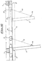
- FIGs 7, 8 and 9 schematically show successive opening steps when an odd number of wings, in particular five wings, are used.
- a further hinge device 3 (see figures 4 and 5 or 5') is provided between a terminal wing and a close adjacent wing, as evidenced by the encircled areas again indicated by reference letter A in figures 7, 8 and 9.
- the terminal wing 2 whose outer end is free, is connected to a sliding rail, for example the upper rail, through a stiff rod 15.
- the rod 15 is in particular hinged at its one end, in 16, to an intermediate location on wing 2 and at its other end to a carriage 17 which is arranged to slide on an appropriate rail.
- the terminal wing 2 is shown, by continuous line, to be in approximately full open position towards the left side (it is to be intended that in this condition the wing is translated in proximity to the left end of a cabinet) and,by dotted line, in both the closed position and the almost full open position towards the right side.
Landscapes
- Engineering & Computer Science (AREA)
- Mechanical Engineering (AREA)
- Vending Machines For Individual Products (AREA)
- Specific Sealing Or Ventilating Devices For Doors And Windows (AREA)
- Power-Operated Mechanisms For Wings (AREA)
- Wing Frames And Configurations (AREA)
- Lock And Its Accessories (AREA)
- Extensible Doors And Revolving Doors (AREA)
- Toys (AREA)
Claims (4)
- Vorrichtung, welche Paare von Flügeln (2) aufweist, die wie ein "Buch" geöffnet und geschlossen werden können, wobei die Flügel (2) eines jeden Flügelpaares voneinander entfernte Enden (2') aufweisen, die in gegenüberliegenden Schienen geführt sind, während die beieinanderliegenden Enden (2") der Flügel bei jedem Flügelpaar zueinander klappbar bzw. um ein Scharnier drehbar sind, und wobei wenigstens zwei beieinanderliegende Paare von Flügeln miteinander durch eine Scharniereinrichtung (3) verbunden sind, welche Zahnräder (4) aufweist, die es allen Flügeln der betroffenen Flügelpaare erlauben, simultan zu gleiten bzw. sich zu verschieben,
dadurch gekennzeichnet, daß die voneinander entfernt liegenden Enden (2') eines jeden Flügelpaares durch eine horizontale obere Schiene gehalten werden und durch eine horizontale untere Schiene geführt werden oder umgekehrt, und daß die Zahnräder (4) von den jeweiligen Flügeln (2) getrennt bzw. auf Abstand zu diesen sind und jedes einen Arm (5) aufweist, welcher damit integriert bzw. einstückig ausgebildet ist, und mit wenigstens einer Rolle (6) versehen ist, die gleitend in einer damit zusammenarbeitenden bzw. zusammenwirkenden Führung (7) aufgenommen ist, welche an der Innenseite eines entsprechenden Flügels (2) angebracht bzw. befestigt ist, wobei die Zahnräder (4) rotierend an einem Bauteil (9) gehalten sind, welches der Reihe nach durch eine der horizontalen oberen oder unteren Führungen für die Flügel (2) gehalten und/oder geführt ist, wobei das Bauteil (9) mittels Scharnieren (12) an damit zusammenarbeitenden aneinanderliegenden Flügeln (2) befestigt ist, wobei durch die Betätigung eines der zwei End-bzw. Abschlußflügel (2) zum bzw. beim Öffnen der Flügel alle Flügel zur gegenüberliegenden Seite bewegt werden und umgekehrt beim Schließen davon weg. - Vorrichtung nach Anspruch 1,
dadurch gekennzeichnet, daß der Durchmesser der Rolle (6) geringer ist als die Breite der damit zusammenarbeitenden Führungen (7). - Vorrichtung nach Anspruch 1 oder 2,
dadurch gekennzeichnet, daß sie weiterhin einen End- bzw. Abschlußflügel (2) beinhaltet, welcher an einem anliegenden Flügel durch eine der Scharniereinrichtungen (3) befestigt ist und ein äußeres freies Ende aufweist, und wenigstens eine steife Stange (15) aufweist, welche zum Verbinden des besagten End- bzw. Abschlußflügels mit einer der oberen und/oder unteren Halteschienen und/oder Führungsschienen vorgesehen ist. - Vorrichtung nach Anspruch 3,
worin die Stange (15) drehbar bzw. schwenkbar an einem Ende davon mit einem mittleren Punkt an dem End- bzw. Abschlußflügel (2) und am anderen Ende davon an einem Wagen befestigt ist, der gleitend in der oberen und/oder unteren Schiene aufgenommen ist.
Applications Claiming Priority (2)
| Application Number | Priority Date | Filing Date | Title |
|---|---|---|---|
| ITMI911018A IT1246592B (it) | 1991-04-12 | 1991-04-12 | Dispositivo atto a realizzare l'apertura e la chiusura per rotazione e scorrimento di una pluralita' di ante |
| IT101891 | 1991-04-12 |
Publications (2)
| Publication Number | Publication Date |
|---|---|
| EP0507993A1 EP0507993A1 (de) | 1992-10-14 |
| EP0507993B1 true EP0507993B1 (de) | 1996-03-06 |
Family
ID=11359576
Family Applications (1)
| Application Number | Title | Priority Date | Filing Date |
|---|---|---|---|
| EP91120744A Expired - Lifetime EP0507993B1 (de) | 1991-04-12 | 1991-12-03 | Vorrichtung zum Öffnen und Schliessen von mehreren Flügeln durch kombiniertes Schwenken und Schieben von denselben |
Country Status (4)
| Country | Link |
|---|---|
| EP (1) | EP0507993B1 (de) |
| AT (1) | ATE135080T1 (de) |
| DE (1) | DE69117733T2 (de) |
| IT (1) | IT1246592B (de) |
Families Citing this family (4)
| Publication number | Priority date | Publication date | Assignee | Title |
|---|---|---|---|---|
| DE9306015U1 (de) * | 1993-04-21 | 1993-06-24 | Paul Hettich GmbH & Co, 4983 Kirchlengern | Faltschiebetürbeschlag |
| FR2705390B1 (fr) * | 1993-05-14 | 1995-08-11 | Accoplas | Dispositif de protection pour ouvertures dans les murs ou analogues. |
| CN103321516B (zh) * | 2013-07-02 | 2015-06-17 | 特威盾门业(苏州)有限公司 | 一种启闭方便的升降折叠门或窗 |
| CN113958215B (zh) * | 2021-11-11 | 2023-02-24 | 广东炬森五金精密制造有限公司 | 一种门体铰链组件 |
Family Cites Families (5)
| Publication number | Priority date | Publication date | Assignee | Title |
|---|---|---|---|---|
| US2151033A (en) * | 1939-03-21 | Folding partition | ||
| US2820514A (en) * | 1955-08-26 | 1958-01-21 | John P Travis | Folding flue window |
| US3344837A (en) * | 1965-07-15 | 1967-10-03 | Hinge Gear Products Inc | Folding panel assembly |
| CH448457A (de) * | 1967-04-12 | 1967-12-15 | Bator Lift Ag | Falttor |
| DE3507863A1 (de) * | 1985-03-06 | 1986-09-11 | Paul Hettich GmbH & Co, 4983 Kirchlengern | Falttuer |
-
1991
- 1991-04-12 IT ITMI911018A patent/IT1246592B/it active IP Right Grant
- 1991-12-03 DE DE69117733T patent/DE69117733T2/de not_active Expired - Fee Related
- 1991-12-03 EP EP91120744A patent/EP0507993B1/de not_active Expired - Lifetime
- 1991-12-03 AT AT91120744T patent/ATE135080T1/de not_active IP Right Cessation
Also Published As
| Publication number | Publication date |
|---|---|
| ATE135080T1 (de) | 1996-03-15 |
| DE69117733D1 (de) | 1996-04-11 |
| ITMI911018A0 (it) | 1991-04-12 |
| ITMI911018A1 (it) | 1992-10-12 |
| EP0507993A1 (de) | 1992-10-14 |
| IT1246592B (it) | 1994-11-24 |
| DE69117733T2 (de) | 1996-07-18 |
Similar Documents
| Publication | Publication Date | Title |
|---|---|---|
| FI75210B (fi) | Anordning foer oeppnande av pao en raet linje staellda moebelskjutdoerrar. | |
| US3618656A (en) | Folding door apparatus | |
| US3906668A (en) | Sliding plug door gear | |
| CA2963451C (en) | Furniture item with sliding leaf mechanism | |
| US3293801A (en) | Apparatus for mounting sliding doors | |
| EP0507993B1 (de) | Vorrichtung zum Öffnen und Schliessen von mehreren Flügeln durch kombiniertes Schwenken und Schieben von denselben | |
| US5036953A (en) | Retractable elevator door | |
| US4350399A (en) | Furniture with space saving door | |
| KR102628399B1 (ko) | 접이식 문의 연결구조 | |
| US2041221A (en) | Operating mechanism for overhead doors | |
| US3260303A (en) | Multi-panel sliding door structure | |
| FI83804C (fi) | Utstaellningsanordning foer flygeldelen av ett foenster, en doerr eller motsvarande. | |
| US5072768A (en) | Hinge for folding closure | |
| JP2000192723A (ja) | 扉構造 | |
| US3022817A (en) | Three-way double garage door | |
| EP3847330B1 (de) | Anordnung aus türplatten und rahmen und schrank mit einer solchen anordnung aus türplatten und rahmen | |
| DE4002232C2 (de) | Antrieb für ein Falttor | |
| GB1590202A (en) | Balancing arrangements for up-and-over doors | |
| JP3040042B2 (ja) | 折戸装置 | |
| JP3350185B2 (ja) | 航空機格納庫の開閉扉 | |
| EP1447507A3 (de) | Schiebesystem für Rahmen, Flügel und dergleichen, wie Flügel von Türen, Fenstern und Möbelteilen | |
| JP2505852Y2 (ja) | 折畳み扉の密閉装置 | |
| JP2505720B2 (ja) | 連動引戸装置 | |
| FR2352143A2 (fr) | Systeme mecanique de commande d'ouverture et de fermeture pour portes | |
| JP2521388Y2 (ja) | 扉・窓の自動開閉機構 |
Legal Events
| Date | Code | Title | Description |
|---|---|---|---|
| PUAI | Public reference made under article 153(3) epc to a published international application that has entered the european phase |
Free format text: ORIGINAL CODE: 0009012 |
|
| AK | Designated contracting states |
Kind code of ref document: A1 Designated state(s): AT BE CH DE DK ES FR GB GR IT LI LU MC NL SE |
|
| 17P | Request for examination filed |
Effective date: 19930323 |
|
| 17Q | First examination report despatched |
Effective date: 19940503 |
|
| GRAA | (expected) grant |
Free format text: ORIGINAL CODE: 0009210 |
|
| AK | Designated contracting states |
Kind code of ref document: B1 Designated state(s): AT BE CH DE DK ES FR GB GR IT LI LU MC NL SE |
|
| PG25 | Lapsed in a contracting state [announced via postgrant information from national office to epo] |
Ref country code: NL Free format text: LAPSE BECAUSE OF FAILURE TO SUBMIT A TRANSLATION OF THE DESCRIPTION OR TO PAY THE FEE WITHIN THE PRESCRIBED TIME-LIMIT Effective date: 19960306 Ref country code: GR Free format text: LAPSE BECAUSE OF FAILURE TO SUBMIT A TRANSLATION OF THE DESCRIPTION OR TO PAY THE FEE WITHIN THE PRESCRIBED TIME-LIMIT Effective date: 19960306 Ref country code: FR Effective date: 19960306 Ref country code: ES Free format text: THE PATENT HAS BEEN ANNULLED BY A DECISION OF A NATIONAL AUTHORITY Effective date: 19960306 Ref country code: DK Effective date: 19960306 Ref country code: BE Effective date: 19960306 |
|
| REF | Corresponds to: |
Ref document number: 135080 Country of ref document: AT Date of ref document: 19960315 Kind code of ref document: T |
|
| REF | Corresponds to: |
Ref document number: 69117733 Country of ref document: DE Date of ref document: 19960411 |
|
| ITF | It: translation for a ep patent filed | ||
| PG25 | Lapsed in a contracting state [announced via postgrant information from national office to epo] |
Ref country code: SE Effective date: 19960606 |
|
| NLV1 | Nl: lapsed or annulled due to failure to fulfill the requirements of art. 29p and 29m of the patents act | ||
| EN | Fr: translation not filed | ||
| PG25 | Lapsed in a contracting state [announced via postgrant information from national office to epo] |
Ref country code: GB Effective date: 19961203 |
|
| PG25 | Lapsed in a contracting state [announced via postgrant information from national office to epo] |
Ref country code: LU Free format text: LAPSE BECAUSE OF NON-PAYMENT OF DUE FEES Effective date: 19961231 |
|
| PLBE | No opposition filed within time limit |
Free format text: ORIGINAL CODE: 0009261 |
|
| STAA | Information on the status of an ep patent application or granted ep patent |
Free format text: STATUS: NO OPPOSITION FILED WITHIN TIME LIMIT |
|
| 26N | No opposition filed | ||
| PG25 | Lapsed in a contracting state [announced via postgrant information from national office to epo] |
Ref country code: MC Effective date: 19970630 |
|
| GBPC | Gb: european patent ceased through non-payment of renewal fee |
Effective date: 19961203 |
|
| PGFP | Annual fee paid to national office [announced via postgrant information from national office to epo] |
Ref country code: DE Payment date: 19981205 Year of fee payment: 8 |
|
| PGFP | Annual fee paid to national office [announced via postgrant information from national office to epo] |
Ref country code: AT Payment date: 19981222 Year of fee payment: 8 |
|
| PGFP | Annual fee paid to national office [announced via postgrant information from national office to epo] |
Ref country code: CH Payment date: 19981223 Year of fee payment: 8 |
|
| PG25 | Lapsed in a contracting state [announced via postgrant information from national office to epo] |
Ref country code: AT Free format text: LAPSE BECAUSE OF NON-PAYMENT OF DUE FEES Effective date: 19991203 |
|
| PG25 | Lapsed in a contracting state [announced via postgrant information from national office to epo] |
Ref country code: LI Free format text: LAPSE BECAUSE OF NON-PAYMENT OF DUE FEES Effective date: 19991231 Ref country code: CH Free format text: LAPSE BECAUSE OF NON-PAYMENT OF DUE FEES Effective date: 19991231 |
|
| PG25 | Lapsed in a contracting state [announced via postgrant information from national office to epo] |
Ref country code: DE Free format text: LAPSE BECAUSE OF NON-PAYMENT OF DUE FEES Effective date: 20001003 |
|
| PG25 | Lapsed in a contracting state [announced via postgrant information from national office to epo] |
Ref country code: IT Free format text: LAPSE BECAUSE OF NON-PAYMENT OF DUE FEES;WARNING: LAPSES OF ITALIAN PATENTS WITH EFFECTIVE DATE BEFORE 2007 MAY HAVE OCCURRED AT ANY TIME BEFORE 2007. THE CORRECT EFFECTIVE DATE MAY BE DIFFERENT FROM THE ONE RECORDED. Effective date: 20051203 |