EP0507666B1 - Elastischer Puffer aus Metalldraht - Google Patents
Elastischer Puffer aus Metalldraht Download PDFInfo
- Publication number
- EP0507666B1 EP0507666B1 EP92400891A EP92400891A EP0507666B1 EP 0507666 B1 EP0507666 B1 EP 0507666B1 EP 92400891 A EP92400891 A EP 92400891A EP 92400891 A EP92400891 A EP 92400891A EP 0507666 B1 EP0507666 B1 EP 0507666B1
- Authority
- EP
- European Patent Office
- Prior art keywords
- strip
- pad
- turns
- metal wire
- preform
- Prior art date
- Legal status (The legal status is an assumption and is not a legal conclusion. Google has not performed a legal analysis and makes no representation as to the accuracy of the status listed.)
- Expired - Lifetime
Links
Images
Classifications
-
- F—MECHANICAL ENGINEERING; LIGHTING; HEATING; WEAPONS; BLASTING
- F01—MACHINES OR ENGINES IN GENERAL; ENGINE PLANTS IN GENERAL; STEAM ENGINES
- F01N—GAS-FLOW SILENCERS OR EXHAUST APPARATUS FOR MACHINES OR ENGINES IN GENERAL; GAS-FLOW SILENCERS OR EXHAUST APPARATUS FOR INTERNAL-COMBUSTION ENGINES
- F01N13/00—Exhaust or silencing apparatus characterised by constructional features
- F01N13/18—Construction facilitating manufacture, assembly, or disassembly
- F01N13/1805—Fixing exhaust manifolds, exhaust pipes or pipe sections to each other, to engine or to vehicle body
- F01N13/1827—Sealings specially adapted for exhaust systems
-
- F—MECHANICAL ENGINEERING; LIGHTING; HEATING; WEAPONS; BLASTING
- F16—ENGINEERING ELEMENTS AND UNITS; GENERAL MEASURES FOR PRODUCING AND MAINTAINING EFFECTIVE FUNCTIONING OF MACHINES OR INSTALLATIONS; THERMAL INSULATION IN GENERAL
- F16F—SPRINGS; SHOCK-ABSORBERS; MEANS FOR DAMPING VIBRATION
- F16F1/00—Springs
- F16F1/36—Springs made of rubber or other material having high internal friction, e.g. thermoplastic elastomers
- F16F1/362—Springs made of rubber or other material having high internal friction, e.g. thermoplastic elastomers made of steel wool, compressed hair, woven or non-woven textile, or like materials
Definitions
- the present invention relates to an elastic pad made of metal wire.
- Anti-vibration elastic pads are known which are produced in particular from a strip of metallic knitted fabric wound on itself to form a solid or annular cylindrical preform which is then compressed axially in a mold so as to entangle the stitches of the knitted fabric and give the tampon a cohesion adapted to the load to which the tampon is subjected during its use.
- the deflections undergone by a pad under load are greater the higher the loads and the higher the initial height under zero load of the pad for a given density of knitting.
- an elastic pad comprising a series of turns of a strip produced from an elastic metal wire in which the turns are arranged in at least two helical layers of opposite steps.
- the meshes of the metal wire are strongly nested in each other both in the radial direction and in the axial direction so that the satisfactory performance is obtained both from the point of view of resistance to radial deformation and of axial flexibility.
- the tampon according to the invention is produced according to a method comprising the steps of producing a substantially cylindrical preform by helical winding according to at least two layers of reverse pitch of a strip produced from an elastic metal wire, and compressed axially to the preform.
- the helical winding has overlapping turns and the strip has a width substantially equal to a height of the pad after axial compression.
- the tampon according to the invention is produced from a strip of elastic metallic wire, for example a strip obtained by flattening a tubular metallic knitted fabric.
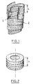
- the metal wire strip is wound according to at least a first layer 1 comprising overlapping turns, and a second layer 2 also comprising overlapping turns and are arranged in a pitch opposite to the pitch of the first layer.
- the preform thus obtained can be produced continuously by winding the strip on a mandrel by moving it laterally in a first direction, for example by descending as illustrated in FIG. 1, then by reversing the direction of lateral displacement of the strip so that it forms a second layer covering the first layer in a reverse pitch, for example by going up as illustrated in FIG. 1.
- the preform obtained can be maintained either by needling the end of the strip on a turn immediately adjacent strip, either by stapling or by fitting retaining rings.
- the preform is then placed in a matrix. In the case where there are provided retaining rings, these are preferably removed at the time of introduction into the matrix. Then the preform is compressed axially and the elastic buffer shown in FIG. 2 is then obtained.
- the outer turns of the strip after compression have been illustrated with a strong line, although in practice the limit between two turns of band is hardly noticeable on the pad after axial compression due to the entanglement of the metal wire meshes.
- the elastic pad according to the invention is preferably produced from a strip of knitted metal wire, it can also be produced from a strip of woven metal wire.
- the elastic pad is annular
- a full pad can be produced by winding the strip on a mandrel of very small diameter so that the axial opening of the preform disappears during axial compression .
- the pad according to the invention can also be made waterproof to serve as an elastic ring in an exhaust coupling of an internal combustion engine.
- the seal is obtained for example by winding a metal strip on the mandrel before winding the strip of metal wire. This strip folds during axial compression so that it provides a seal without significantly modifying the axial stiffness of the pad.
Landscapes
- Engineering & Computer Science (AREA)
- General Engineering & Computer Science (AREA)
- Mechanical Engineering (AREA)
- Textile Engineering (AREA)
- Chemical & Material Sciences (AREA)
- Combustion & Propulsion (AREA)
- Springs (AREA)
- Absorbent Articles And Supports Therefor (AREA)
Claims (4)
- Elastischer Puffer umfassend eine Reihe von Windungen eines aus einem elastischen Metalldraht hergestellten Bandes, dadurch gekennzeichnet, daß die Windungen in zumindest zwei gegenläufigen schraubenförmigen Schichten vorgesehen sind.
- Verfahren zur Herstellung eines elastischen Puffers gemäß Anspruch 1, gekennzeichnet durch den Schritt der Herstellung eines im wesentlichen zylindrischen Vorformlings durch schraubenförmiges Wickeln eines aus elastischem Metalldraht hergestellten Bandes in wenigstens zwei gegenläufigen Schichten (1, 2) und den Schritt der axialen Komprimierung des Vorformlings.
- Verfahren nach Anspruch 2, dadurch gekennzeichnet, daß die schraubenförmige Wicklung einander überlappende Windungen aufweist.
- Verfahren nach Anspruch 2 oder 3, dadurch gekennzeichnet, daß das Band eine Breite (L) hat, die im wesentlichen gleich einer Höhe (H) des Puffers nach der axialen Komprimierung ist.
Applications Claiming Priority (2)
| Application Number | Priority Date | Filing Date | Title |
|---|---|---|---|
| FR9104183 | 1991-04-05 | ||
| FR9104183A FR2674925B1 (fr) | 1991-04-05 | 1991-04-05 | Tampon elastique en fil metallique. |
Publications (2)
| Publication Number | Publication Date |
|---|---|
| EP0507666A1 EP0507666A1 (de) | 1992-10-07 |
| EP0507666B1 true EP0507666B1 (de) | 1994-06-22 |
Family
ID=9411533
Family Applications (1)
| Application Number | Title | Priority Date | Filing Date |
|---|---|---|---|
| EP92400891A Expired - Lifetime EP0507666B1 (de) | 1991-04-05 | 1992-03-31 | Elastischer Puffer aus Metalldraht |
Country Status (5)
| Country | Link |
|---|---|
| US (1) | US5280888A (de) |
| EP (1) | EP0507666B1 (de) |
| JP (1) | JPH0599256A (de) |
| DE (1) | DE69200200T2 (de) |
| FR (1) | FR2674925B1 (de) |
Families Citing this family (7)
| Publication number | Priority date | Publication date | Assignee | Title |
|---|---|---|---|---|
| USRE40183E1 (en) | 1991-10-04 | 2008-03-25 | Wyeth Holdings Corporation | 7-Substituted-9-substituted amino-6-demethyl-6-deoxytetracyclines |
| US5494903A (en) | 1991-10-04 | 1996-02-27 | American Cyanamid Company | 7-substituted-9-substituted amino-6-demethyl-6-deoxytetracyclines |
| NO962336L (no) * | 1995-06-06 | 1996-12-09 | Target Therapeutics Inc | Vaso-okklusiv spiral |
| DE19626754A1 (de) * | 1996-07-03 | 1998-01-08 | Alfred Ernst Buck | Federelement mit gestricktem Formkörper |
| KR100281630B1 (ko) * | 1998-01-20 | 2001-02-15 | 김용호 | 자동차 배기관용 디커플러 |
| US20020063368A1 (en) * | 2000-11-29 | 2002-05-30 | Kabir Omar M. | Mesh bearing damper for an energy storage rotor |
| CN115780701B (zh) * | 2022-11-09 | 2026-04-07 | 八环科技集团股份有限公司 | 金属缓冲材料的加工方法、带有金属缓冲环的关节轴承 |
Family Cites Families (9)
| Publication number | Priority date | Publication date | Assignee | Title |
|---|---|---|---|---|
| US2755079A (en) * | 1952-02-29 | 1956-07-17 | Otto H York | Elastic metal mesh tubular bellows |
| GB836519A (en) * | 1958-09-11 | 1960-06-01 | Metal Textile Corp | Improvements in resilient vibration dampening and shock absorptive cushioning elements |
| US3186701A (en) * | 1963-03-04 | 1965-06-01 | Sr Ralph L Skinner | Spring |
| US4312599A (en) * | 1979-10-22 | 1982-01-26 | General Electric Company | High temperature article, article retainer, and cushion |
| SU1298446A1 (ru) * | 1985-07-08 | 1987-03-23 | Войсковая Часть 25840 | Амортизатор |
| JPS63104829A (ja) * | 1986-10-21 | 1988-05-10 | 三葉通商株式会社 | 紙缶用紙筒並びにその製造方法及び装置 |
| JPH07101065B2 (ja) * | 1988-01-19 | 1995-11-01 | オイレス工業株式会社 | 排気管継手用球面シール体の製造方法 |
| US5052404A (en) * | 1989-03-02 | 1991-10-01 | The Microspring Company, Inc. | Torque transmitter |
| FR2659709B1 (fr) * | 1990-03-15 | 1992-07-17 | Dubois Jacques | Manchon elastique anti-vibratoire notamment pour accouplement d'echappement, et procede de realisation d'un manchon elastique anti-vibratoire. |
-
1991
- 1991-04-05 FR FR9104183A patent/FR2674925B1/fr not_active Expired - Fee Related
-
1992
- 1992-03-24 US US07/856,700 patent/US5280888A/en not_active Expired - Fee Related
- 1992-03-31 DE DE69200200T patent/DE69200200T2/de not_active Expired - Fee Related
- 1992-03-31 EP EP92400891A patent/EP0507666B1/de not_active Expired - Lifetime
- 1992-04-03 JP JP4081245A patent/JPH0599256A/ja active Pending
Also Published As
| Publication number | Publication date |
|---|---|
| JPH0599256A (ja) | 1993-04-20 |
| FR2674925B1 (fr) | 1993-07-30 |
| DE69200200T2 (de) | 1995-02-02 |
| EP0507666A1 (de) | 1992-10-07 |
| US5280888A (en) | 1994-01-25 |
| FR2674925A1 (fr) | 1992-10-09 |
| DE69200200D1 (de) | 1994-07-28 |
Similar Documents
| Publication | Publication Date | Title |
|---|---|---|
| EP0507666B1 (de) | Elastischer Puffer aus Metalldraht | |
| EP0796404B1 (de) | Flexible rohrleitung mit einer gehefteten verstärkungslage | |
| EP0610108B1 (de) | Klemmring und Verfahren zur Herstellung | |
| EP4242364B1 (de) | Rohr mit verstärkungsschicht | |
| FR2831238A1 (fr) | Conduite tubulaire flexible pour le transport d'hydrocarbures a carcasse constituee d'un element allonge enroule agrafe par un feuillard | |
| EP0337854A1 (de) | Gelenkige Abgasrohrverbindung | |
| WO1998032957A1 (fr) | Flexible de decouplage monte dans une ligne d'echappement d'un moteur de vehicule automobile | |
| OA12796A (en) | Dispositif pour limiter le flambage latéral des nappes d'armures d'une conduite flexible. | |
| FR2887290A1 (fr) | Tube souple pour le tuyau d'echappement d'une automobile | |
| EP0447294A1 (de) | Elastische Antischwingungsbuchse, insbesondere für Abgasrohrverbindung und Verfahren zur Herstellung einer elastischen Antischwingungsbuchse | |
| FR2676502A1 (fr) | Joint flexible pour un tuyau d'echappement de vehicule automobile. | |
| EP0887577A1 (de) | Metallische Verbundfederdichtung und ihr Herstellungsverfahren | |
| FR2861270A1 (fr) | Chapelet de ressorts helicoidaux en poches pour suspensions a ressorts ensaches de matelas de literie | |
| BE1010999A5 (fr) | Piston. | |
| WO1998040297A1 (fr) | Enrouleuse pour matelas fibreux | |
| EP1852245A2 (de) | Verfahren zur Herstellung eines Verbundstoffs aus Polymer(en) und einer Textil- oder Metallverstärkung, mittels dieses Verfahrens erhaltener Verbundstoff und daraus bestehende Entkopplungsmanschette | |
| JP2008174384A (ja) | 継ぎ目のない梱包用ベルト | |
| EP0493188B1 (de) | Wärmeschrumpfbare Hülse mit metallischem Drahtgewebe | |
| EP0085062B1 (de) | Zusammengesetzter maschenförmiger werkstoff, formgebung dieses werkstoffes und daraus geformter gegenstand | |
| EP0705404B1 (de) | Metallteil mit einem element das eine kugelwand hat, verfahren zur herstellung des metallteiles und kugelkupplung für eine abgasvorrichtung | |
| FR2959223A1 (fr) | Elingue de levage | |
| RU95118271A (ru) | Комбинированная труба высокого давления | |
| EP0434529A1 (de) | Auspuffdichtung und Anwendung bei einer biegsamen Auspuffkupplung | |
| EP4137214B1 (de) | Seil mit radialer naht und sein herstellungsverfahren | |
| EP2803763B1 (de) | Perfektioniertes Zug- und Hubkabel, und Herstellungsverfahren dieses Kabels |
Legal Events
| Date | Code | Title | Description |
|---|---|---|---|
| PUAI | Public reference made under article 153(3) epc to a published international application that has entered the european phase |
Free format text: ORIGINAL CODE: 0009012 |
|
| 17P | Request for examination filed |
Effective date: 19920401 |
|
| AK | Designated contracting states |
Kind code of ref document: A1 Designated state(s): DE ES GB IT NL SE |
|
| 17Q | First examination report despatched |
Effective date: 19931206 |
|
| GRAA | (expected) grant |
Free format text: ORIGINAL CODE: 0009210 |
|
| AK | Designated contracting states |
Kind code of ref document: B1 Designated state(s): DE ES GB IT NL SE |
|
| PG25 | Lapsed in a contracting state [announced via postgrant information from national office to epo] |
Ref country code: NL Effective date: 19940622 Ref country code: ES Free format text: THE PATENT HAS BEEN ANNULLED BY A DECISION OF A NATIONAL AUTHORITY Effective date: 19940622 |
|
| REF | Corresponds to: |
Ref document number: 69200200 Country of ref document: DE Date of ref document: 19940728 |
|
| ITF | It: translation for a ep patent filed | ||
| PG25 | Lapsed in a contracting state [announced via postgrant information from national office to epo] |
Ref country code: SE Effective date: 19940922 |
|
| GBT | Gb: translation of ep patent filed (gb section 77(6)(a)/1977) |
Effective date: 19940830 |
|
| NLV1 | Nl: lapsed or annulled due to failure to fulfill the requirements of art. 29p and 29m of the patents act | ||
| PLBE | No opposition filed within time limit |
Free format text: ORIGINAL CODE: 0009261 |
|
| STAA | Information on the status of an ep patent application or granted ep patent |
Free format text: STATUS: NO OPPOSITION FILED WITHIN TIME LIMIT |
|
| 26N | No opposition filed | ||
| PGFP | Annual fee paid to national office [announced via postgrant information from national office to epo] |
Ref country code: GB Payment date: 19970320 Year of fee payment: 6 |
|
| PGFP | Annual fee paid to national office [announced via postgrant information from national office to epo] |
Ref country code: DE Payment date: 19970430 Year of fee payment: 6 |
|
| PG25 | Lapsed in a contracting state [announced via postgrant information from national office to epo] |
Ref country code: GB Free format text: LAPSE BECAUSE OF NON-PAYMENT OF DUE FEES Effective date: 19980331 |
|
| GBPC | Gb: european patent ceased through non-payment of renewal fee |
Effective date: 19980331 |
|
| PG25 | Lapsed in a contracting state [announced via postgrant information from national office to epo] |
Ref country code: DE Free format text: LAPSE BECAUSE OF NON-PAYMENT OF DUE FEES Effective date: 19981201 |
|
| PG25 | Lapsed in a contracting state [announced via postgrant information from national office to epo] |
Ref country code: IT Free format text: LAPSE BECAUSE OF NON-PAYMENT OF DUE FEES;WARNING: LAPSES OF ITALIAN PATENTS WITH EFFECTIVE DATE BEFORE 2007 MAY HAVE OCCURRED AT ANY TIME BEFORE 2007. THE CORRECT EFFECTIVE DATE MAY BE DIFFERENT FROM THE ONE RECORDED. Effective date: 20050331 |