EP0507635B1 - Plate clamping system for a duplicating machine - Google Patents
Plate clamping system for a duplicating machine Download PDFInfo
- Publication number
- EP0507635B1 EP0507635B1 EP92303021A EP92303021A EP0507635B1 EP 0507635 B1 EP0507635 B1 EP 0507635B1 EP 92303021 A EP92303021 A EP 92303021A EP 92303021 A EP92303021 A EP 92303021A EP 0507635 B1 EP0507635 B1 EP 0507635B1
- Authority
- EP
- European Patent Office
- Prior art keywords
- plate
- clamp
- leading edge
- assembly
- trailing edge
- Prior art date
- Legal status (The legal status is an assumption and is not a legal conclusion. Google has not performed a legal analysis and makes no representation as to the accuracy of the status listed.)
- Expired - Lifetime
Links
- 230000000712 assembly Effects 0.000 claims abstract description 25
- 238000000429 assembly Methods 0.000 claims abstract description 25
- 230000008878 coupling Effects 0.000 claims description 14
- 238000010168 coupling process Methods 0.000 claims description 14
- 238000005859 coupling reaction Methods 0.000 claims description 14
- 238000009434 installation Methods 0.000 abstract description 4
- 230000007246 mechanism Effects 0.000 description 18
- 238000000034 method Methods 0.000 description 3
- 210000003813 thumb Anatomy 0.000 description 3
- 229910001220 stainless steel Inorganic materials 0.000 description 2
- 239000010935 stainless steel Substances 0.000 description 2
- 239000000758 substrate Substances 0.000 description 2
- 229910000906 Bronze Inorganic materials 0.000 description 1
- 239000003831 antifriction material Substances 0.000 description 1
- 239000010974 bronze Substances 0.000 description 1
- 238000010276 construction Methods 0.000 description 1
- KUNSUQLRTQLHQQ-UHFFFAOYSA-N copper tin Chemical compound [Cu].[Sn] KUNSUQLRTQLHQQ-UHFFFAOYSA-N 0.000 description 1
- 238000012937 correction Methods 0.000 description 1
- 230000000694 effects Effects 0.000 description 1
- 238000004519 manufacturing process Methods 0.000 description 1
- 239000002699 waste material Substances 0.000 description 1
Images


Classifications
-
- B—PERFORMING OPERATIONS; TRANSPORTING
- B41—PRINTING; LINING MACHINES; TYPEWRITERS; STAMPS
- B41L—APPARATUS OR DEVICES FOR MANIFOLDING, DUPLICATING OR PRINTING FOR OFFICE OR OTHER COMMERCIAL PURPOSES; ADDRESSING MACHINES OR LIKE SERIES-PRINTING MACHINES
- B41L29/00—Devices for attaching printing elements or formes to supports
- B41L29/12—Devices for attaching printing elements or formes to supports for attaching flexible printing formes
- B41L29/14—Clamping devices
-
- B—PERFORMING OPERATIONS; TRANSPORTING
- B41—PRINTING; LINING MACHINES; TYPEWRITERS; STAMPS
- B41F—PRINTING MACHINES OR PRESSES
- B41F27/00—Devices for attaching printing elements or formes to supports
- B41F27/12—Devices for attaching printing elements or formes to supports for attaching flexible printing formes
- B41F27/1218—Devices for attaching printing elements or formes to supports for attaching flexible printing formes comprising printing plate tensioning devices
- B41F27/1225—Devices for attaching printing elements or formes to supports for attaching flexible printing formes comprising printing plate tensioning devices moving in the printing plate end substantially rectilinearly
- B41F27/1231—Devices for attaching printing elements or formes to supports for attaching flexible printing formes comprising printing plate tensioning devices moving in the printing plate end substantially rectilinearly by translatory motion substantially tangential to support surface
-
- B—PERFORMING OPERATIONS; TRANSPORTING
- B41—PRINTING; LINING MACHINES; TYPEWRITERS; STAMPS
- B41P—INDEXING SCHEME RELATING TO PRINTING, LINING MACHINES, TYPEWRITERS, AND TO STAMPS
- B41P2227/00—Mounting or handling printing plates; Forming printing surfaces in situ
- B41P2227/40—Adjusting means for printing plates on the cylinder
- B41P2227/43—Adjusting means for printing plates on the cylinder diagonally
-
- Y—GENERAL TAGGING OF NEW TECHNOLOGICAL DEVELOPMENTS; GENERAL TAGGING OF CROSS-SECTIONAL TECHNOLOGIES SPANNING OVER SEVERAL SECTIONS OF THE IPC; TECHNICAL SUBJECTS COVERED BY FORMER USPC CROSS-REFERENCE ART COLLECTIONS [XRACs] AND DIGESTS
- Y10—TECHNICAL SUBJECTS COVERED BY FORMER USPC
- Y10S—TECHNICAL SUBJECTS COVERED BY FORMER USPC CROSS-REFERENCE ART COLLECTIONS [XRACs] AND DIGESTS
- Y10S101/00—Printing
- Y10S101/36—Means for registering or alignment of print plates on print press structure
Definitions
- the present invention relates in general to a duplicating machine such as a printing press and in particular to a plate clamping system for adjusting the plate or master with respect to the plate cylinder.
- duplicating processes which depend on positioning an image on a printing substrate such as a copy sheet in accurate alignment with a predetermined reference on a plate or master cylinder and adjusting the image position relative to the reference, if necessary, in order to achieve requisite printing quality on the substrate.
- One such duplicating process is the offset duplicating process.
- a master carrying assembly for example, a cylinder, serves to hold the master or plate during the cyclical operation that effects the transfer of images to the copy paper.
- the head end of the master is held securely by the master carrying assembly.
- the holding mechanism may lake various forms including one form which clamps a master end.
- the master holding or securing mechanism may have a series of pins projecting from a bar extending generally parallel to the cylinder axis and mounted adjacent the cylinder periphery.
- the master end holding means is preferably adjustable, both angularly and perpendicularly, relative to the direction of movement of the master carrying assembly to suitablyalign the print on the copy sheet. This is because the orientation of the image on the master, for example the lines of print across the width of the master, are not necessarily precisely related to the master end or to the perforations in the master, which are the portions of the master engaged by the master holding means.
- a clamp commonly has a straight edge against which one end of the master is pressed before the master is gripped to align the master relative to the carrying assembly. If the end of the master is not parallel to the lines of print, then the duplicated image will be skewed on the copy sheet.
- a pin bar is provided to engage the perforations. It is understandable how an image may be misaligned on a copy sheet if the perforations or pin holes along the edge of a master are not aligned properly relative to the image on the master.
- Prior art devices have structures which adjust the alignment of the pin bars.
- One example of such structure is a thumb screw positioned to one side of a center pivot for the beam which connects the pin bar to the frame of the master carrying assembly.
- the thumb screw has posts on either side extending in opposite directions which have left-hand and right-hand threads, respectively.
- One post is threaded in a fixed support and the other is threaded in a support which is a part of the pivotable beam.
- Turning of the screw draws one side of the beam toward the fixed support or forces that side of the beam away from the fixed support, depending on which direction the thumb screw is turned, thereby pivoting the beam and the pin bar with it. It is in this way that the master is aligned.
- Such a structure is adapted for installation on the A.B. Dick Company (assignee of the present invention) Model 360 offset press.
- leading edge clamping assembly when the leading edge clamping assembly is adjusted from both sides, it requires a high degree of operator skill to properly position the leading edge clamp assembly to correct the problem of skewing.
- trailing edge clamp assembly must be separately adjusted to compensate for the movement of the tail end of the plate or master which has moved because of the adjustment of the leading edge clamp assembly.
- the prior art does not make any effort to correct for varying plate thicknesses except by using the operator with a high degree of skill to adjust the proper pressure of the clamp assembly to accommodate varying sizes or thicknesses of the plates or masters.
- German patent 893,343, EP-A-0,401,500, German patent 1,536,954 and U.S. Patent No. 4,785,736 all disclose mechanisms for adjusting the leading edge and trailing edge plate clamps.
- German patent 893,343 it appears that each of the leading edge and trailing edge plate clamps can be both rotated about a center pivot point and axially moved in either direction. They can also cause both the leading edge and trailing edge plate clamp assemblies to move axially in the same direction.
- EP-A-0,401,500 discloses a mechanism for adjusting the leading and trailing edge clamps by rotating two separate pivot levers, one at each end of the plate clamps, that are coupled to both plate clamps. When the levers are rotated, one plate clamp moves axially in one direction and the other plate clamp moves axially in the other direction simultaneously.
- German patent 1,536,954 has a similar mechanism except that a single lever is coupled to the center of each plate clamp and is rotatably mounted to the frame at the center point of the lever. Adjusting the lever to move the leading edge plate clamp axially in one direction simultaneously moves the trailing edge plate clamp in the opposite direction.
- EP-A-0308799 discloses a printing plate skewing assembly utilising slidable coupling plates, carried in a groove on a plate cylinder.
- the coupling plates carry printing plate clamping and tensioning assemblies and are slidable through their connections to pivotable levers which are positioned at opposing ends of the plate cylinder groove.
- duplicating machine refers to a variety of devices including duplicators, copiers, printing presses such as offset or letter presses and the like.
- a duplicating machine having a plate cylinder rotatably mounted on a frame with plate holding assemblies having means to hold the leading and trailing edges of a plate, characterised in that the plate clamping system comprises:
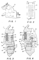
- FIG. 1 is a partial side view of a conventional duplicating machine 10 having a plate cylinder 11, a blanket cylinder 12, and an impression cylinder 14.
- a master or plate such as plate 19 illustrated in FIG. 2 having indicia 21 thereon is placed on plate cylinder 11.
- Blanket cylinder 12 is periodically brought into contact first with plate cylinder 11 to transfer the image from the master 19 to the blanket cylinder 12 and then is brought into contact with the impression cylinder 14 to transfer the image to the copy paper passing under impression cylinder 14.
- the master 19 has three holes 13, 15 and 17 which must be attached to register pins on the leading edge and trailing edge clamp assemblies. It is easily understood that the pin holes precisely locate the image with respect to the register pins on the plate cylinder 11.
- the pin registers on the plate cylinder 11 have to be properly positioned axially and angularly with respect to the direction of movement of the plate cylinder 11 and the plate cylinder 11 has to be registered to the blanket cylinder 12 and through the impression cylinder 14 in order for a correct image to be transferred to the paper copy passing under the impression cylinder 14. Since all of these elements cannot be precisely arranged with respect to each other in every instance because of the imprecise manner in which the master or plate is made, there must of necessity be a way to correct the skewing on the final copy paper so that the printing is aligned properly with the copy paper.
- FIG. 3 is a partial cross-sectional view of the preferred embodiment of the leading edge and trailing edge plate clamp or holding assemblies of the present invention illustrating the preferred manner in which skewing adjustments for the leading edge assembly and the trailing edge assembly are accomplished simultaneously.
- the plate cylinder 11 has a leading edge plate clamp or holding assembly 16 and a trailing edge plate clamp or holding assembly 18.
- the leading edge plate clamp assembly 16 has a beam element 22 and a C-shaped clamp 20. The clamp may be more clearly seen in FIGS. 9B, 9C and 10B.
- the trailing edge plate clamp assembly 18 includes a beam element 26 and C-shaped clamp assembly 24.
- a spring member 28 biases the trailing edge plate clamp assembly 18 away from the plate cylinder frame 40 to provide tension to the master or plate 19 (shown in FIG. 2) attached thereto and hold the plate 19 uniformly tight against the cylinder in its skewed orientation.
- the leading edge plate clamp assembly 16 has register pins 50 and 52 (more clearly shown in FIG. 4) while the trailing edge plate clamp assembly 18 includes a single register pin 54. These are the register pins to which the plate 19 in FIG. 2 is attached with the pin holes 13, 15 and 17.
- the leading edge plate clamp assembly 16 and the trailing edge plate clamp assembly 18 are shown in FIG 3 in their closed positions. It will be noted that an eccentric pivot pin 27 in the beam 22 of the leading edge plate clamp assembly 16 is attached to bell crank link 23 at one end thereof.
- link 23 rides in a slot 39 in the beam element 26 in the trailing edge plate clamp assembly 18. This can be seen more clearly from the top view in FIG. 4.
- One end 25 of the bell crank link 23 is pivotally coupled at 27 to the beam 22 in the leading edge plate clamp assembly 16.
- the bell crank arm 29 is positioned in a slot 31 in the plate cylinder frame 40. Whenever the leading edge plate clamp assembly 16 is moved in FIG. 3 or FIG.
- the movement of the bell crank linkage about end 25 causes a pivotal movement by arm 29 in slot 31 to cause the far end 35 of the bell crank link 23 to move in the direction of arrow 33, thus causing a force to be applied to the beam 26 to move it in a direction to automatically adjust the trailing edge plate clamp assembly and cause it to be in proper alignment with the trailing edge of the skewed front end of the master or plate.
- the pivot 27 is an eccentric pivot, which, when rotated, can adjust the initial relationship of the leading edge plate clamp assembly 16 to the trailing edge plate clamp assembly 18. Once it is adjusted, a locking set screw 32 or other locking device may be used to prevent further rotation of the eccentric pivot 27. Thereafter, any skewing adjustment of the leading edge plate clamp assembly 16 automatically adjusts the trailing edge plate clamp assembly 18 axially to compensate for the skewed front end of the master or plate.
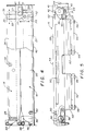
- FIG. 4 is an illustrative top view of the preferred embodiment of the leading edge plate clamp assembly 16 and the trailing edge plate clamp assembly 18. It will be seen in FIG. 4 that the beam 22 in the leading edge clamp assembly 16 is attached by bolts 46 and 48 to the plate cylinder at one end thereof. It also has a fixed register pin 50 and a register pin 52 that moves with the outer end of beam 22. Thus, a skewing adjustment screw 42 is threadedly inserted in the beam 22 and contacts the plate cylinder frame 40. By rotating the skewing adjustment screw 42, the beam 22 can pivot about bolt 46 in a direction horizontally toward the trailing clamp assembly 18 and tangentially to the plate cylinder 11 causing outer pin 52 to move from its position shown in FIG. 4.
- Trailing plate clamp 18 has one register pin 54 for receiving the orifice 17 in the trailing edge of the master 19 shown in FIG. 2.
- bell crank link 23 is pivoted about point 27 by arm 29 in slot 31. Because slot 31 is fixed in the plate cylinder frame 40, movement of the bell crank link 23 in a clockwise direction applies an axial force in the direction to the right in FIG.
- Calibration scale 43 may be coupled to the skew adjusting screw 42 to give the operator an indication of how much skew is being accomplished by calibrated rotation of screw 42.
- One of the slide clamps 44 is shown more clearly on the right end of clamp assembly 16 in FIG. 5.
- the slide clamps 44 have a small vertical clearance 41 with the base of the clamp assembly 16 or 18 of about 0.005 or 0.01cm (0.002 or 0.004 inches). They have a horizontal clearance 45 with the base of the clamp assemblies 16 or 18 of approximately 0.226 to 0.25cm (0.093 to 0.100 inches) for slidable adjustment of the clamp assemblies 16 and 18.
- FIG. 5 is a front view of the leading edge plate clamp assembly 16 illustrated in FIG. 4.
- An end view of the bell link 23 is shown illustrating the bell crank arm pivotally held in slot 31 and with the end portion 35 in slot 39.
- a portion of the spring mechanism for compensating for the variable thickness of plates or masters that may be used.
- first and second elongated bars 62 and 64 are coupled by any well-known means 66, such as screws, to the bottom edge 60 of the C-shaped clamp 20 of leading edge clamp assembly 16.
- Slide clamps 44 as stated earlier, have the proper clearance with clamp assemblies 16 and 18 to allow lateral adjustment of the leading edge plate clamp assembly 16 during installation and for leading and trailing edge clamp movement during adjustment of the plate 19 with respect to the cylinder 11.
- a rotatable actuator 56 is coupled to a connecting link 58 that is also pivotally coupled to the spring bar 68 as shown more clearly in FIGS. 9A and 10A.
- FIG. 6 is a partial cross-sectional view of an alternate embodiment of the leading edge and trailing edge plate clamp or holding assemblies of the present invention illustrating another manner in which skewing adjustments for the leading edge assembly and the trailing edge assembly may be accomplished simultaneously.
- the plate cylinder 11 has a leading edge plate clamp or holding assembly 16 and a trailing edge plate clamp or holding assembly 18 similar to that shown in FIG. 3.
- the construction of the assembly shown in FIG. 6 is similar to that shown in FIG. 3 except for the means for automatically adjusting the trailing edge assembly as the leading edge is adjusted for skew.
- an eccentric pivot pin 30 in the beam 22 of the leading edge plate clamp assembly 16 has a link 34 attached to it at one end thereof.
- the other end of link 34 is attached to a squareheaded pivot pin 37 which rides in a slot 39. Again, this can be more clearly seen from a top view in FIG. 7.
- a second link 36 is pivotally connected to the squareheaded pivot pin 37 and to a pin 38 attached to the plate cylinder frame 40.
- the movement of linkage 34 with respect to linkage 36 causes a force to be applied to the beam 26 to move it in a direction automatically adjusting the trailing edge plate clamp assembly to cause it to be in proper alignment with the trailing edge of the skewed front end of the master or plate.
- the pivot 30 is an eccentric device which, when rotated, can adjust the initial relationship of the leading edge plate clamp assembly 16 to the trailing edge plate clamp assembly 18. Once it is adjusted, a locking set screw 32 is fixed to prevent further rotation of the eccentric pivot 30. Thereafter, any skewing adjustment of the leading edge plate clamp assembly 16 automatically adjusts the trailing edge plate clamp assembly 18 axially to compensate for the skewed front end of the master or plate.
- FIG. 7 is an illustrative top view of the alternate embodiment of the leading edge plate clamp assembly 16 and the trailing edge plate clamp assembly 18. It will be seen in FIG. 7 that the beam 22 in the leading edge clamp assembly 16 is attached by bolts 46 and 48 to the plate cylinder 40 at one end thereof. It also has a fixed register pin 50 and a register pin 52 that moves with the outer end of the beam 22. Thus, a skewing adjustment screw 42 is threadedly inserted in the beam 22 and contacts the plate cylinder frame 40.
- the beam 22 By rotating the skewing adjusting screw 42, the beam 22 can be flexed as a cantilevered beam or, preferably, pivoted about bolt 46 in a direction horizontally toward the trailing clamp assembly 18 and tangential to the plate cylinder 11 causing outer pin 52 to move from its position shown in FIG. 7.
- the register pin 50 is essentially fixed because of its position near the end of the beam 22 that is attached to the plate cylinder frame 40, movement of the beam by the skewing screw 42 angularly adjusts the skew of the plate or master attached to the register pins 50 and 52.
- Trailing plate clamp 18 has one register pin 54 for receiving the orifice 17 in the trailing edge of the master 19 shown in FIG. 2.
- a calibration scale 43 may be coupled to the skew adjusting screw 42 to give the operator an indication of how much skew is being accomplished by calibrated rotation of screw 42.
- FIG. 8 is a front view of the leading edge plate clamp assembly 16 illustrated in FIG. 7.
- the linkage 34 and 36 is shown as well as the squareheaded pin 37 in slot 39 of beam 26 in the trailing edge assembly 18 for adjusting the trailing edge plate clamp assembly 18 automatically with an adjustment of the leading edge plate clamp assembly 16 for skew.
- Also shown in FIG. 8 is a portion of the spring mechanism for compensating for the variable thickness of plates or masters that may be used.
- first and second elongated bars 62 and 64 are coupled to the bottom edge 60 of the C-shaped clamp 20 of leading edge clamp assembly 16 in the manner as shown in FIG. 5.
- Slide clamp 44 allows lateral adjustment of the leading edge plate clamp assembly 16 during installation.
- the rotatable actuator 56 is shown coupled to the connecting link 58 that is also pivotally coupled to the spring bar 68 as shown in FIGS. 9A and 10A.
- the cantilevered beam 22 has an elongated clamp element 20 associated with beam 22 for selective engagement with the beam 22 to clamp or release the leading edge of a plate therein.
- Spring bar 68, linkages 70 and 72 and carriage assemblies 82 and 84 are interposed between the beam 22 and the clamp element 20 for automatically compensating for variations in the thickness of the plate being clamped.
- the elongated spring bar 68 is slidably associated in the center portion 92 thereof with the beam 22 through a wear strip 90.
- the wear strip 90 is constructed from an anti-friction material such as an oil impregnated sintered bronze, a suitable plastic and the like for providing a means of making a "factory adjustment" to accommodate for the manufacturing tolerances of components.
- the actuator 56 is coupled through connecting link 58 to one end 96 of spring bar 68 for moving the spring bar 68 axially to cause toggle links 70 and 72 to move the elongated clamp 20 into engagement with the beam 22 to clamp the edge of the plate therein.
- the spring bar 68 is thicker in the center portion 92 and tapered toward each end 74 and 76 such that the spring bar 68 can flex at each end to accommodate variations in the thickness of the plate being clamped.
- First and second spaced elongated bars 62 and 64 are each attached at each end axially to the plate clamp bottom edge 60 for distributing a force applied to the first and second space bars 62 and 64 equally to the plate clamp 20 at each end of each space bar.
- Carriage elements 82 and 84 are mounted on a respective one of the first and second space bars 62 and 64 with each carriage element pivotally coupled to a respective toggle link at 78 and 80, respectively, on the ends of the spring bar 68 for receiving a force from the toggle links 70 and 72 when the spring bar 68 is moved axially.
- the spaced bars 62 and 64 distribute the received force to the plate clamp 20 equally at each end of each space bar 62 and 64.
- FIG. 9A the rotatable actuator 56 has a first detent 98 therein which receives a ball 100 urged therein by spring 102.
- the rotatable actuator will lock and be held in its selected position and will not move because of incidental forces such as vibration.
- the position of the clamp 20 with relation to beam 22 is illustrated in its open position in FIG. 9B and is shown movably associated with beam 22 through a pivot point 94.
- FIG. 9C illustrates the relationship of the clamp 20 to the beam 22 when it has been moved forward but not clamped over the leading edge of the plate or master.
- FIG. 10A illustrates the leading edge plate clamp assembly 16 in its closed position.
- the end view of FIG. 10B shows the toggle link 70 having been moved to the vertical position by the sliding motion of spring bar 68.
- rotatable actuator 56 has a connecting link 58 pivotally coupling the rotatable actuator 56 and the one end 96 of the spring bar such that rotation of the rotatable actuator 56 moves the spring bar 68 axially to cause the clamp 20 to move into engagement with the beam 22.
- First and second spaced detents 98 and 104 in the rotatable actuator 56 represent open and clamped positions of the plate clamp assembly 16.
- Ball 100 sequentially engages the first and second detents 98 and 104 as the actuator 56 is rotated and spring 102 in the plate cylinder housing 40 forces the ball 100 into the first and second detents 98 and 104 in the open and clamped positions of the actuator 56 to prevent unwanted rotary motion of the actuator 56 due to incidental forces such as vibration.
- Spring members 86 and 88 may be interposed between the carriage assemblies 82 and 84 and their respective attachment to the underside 60 of the C-shaped plate clamp 20 for the purpose of biasing the plate clamp 20 into position as illustrated in FIG. 9C.
- the novel plate clamp assembly of the present invention provides a novel apparatus for adjusting the leading edge plate clamp assembly to enable skewing of the plate as desired, couples the leading edge plate clamp assembly to the trailing edge plate clamp assembly such that adjusting the leading edge plate clamp assembly to skew the plate automatically adjusts the trailing edge plate clamp assembly in proper alignment with the trailing edge of the skewed plate and it may provide spring means interposed between the plate cylinder and each of the clamps for automatically compensating for variations in the thickness of the plate being clamped.
- the preferred embodiment of the improved apparatus for adjusting the leading edge plate clamp assembly to enable skewing of the plate uses a beam pivotally attached to the plate cylinder frame at one end.
- a plate clamp is associated with the beam to form the leading edge plate clamping assembly and the plate clamp is operatively associated with the beam to clamp or release the leading edge of the plate inserted therein.
- a calibrated screw or other adjusting means is coupled to the other end of the pivoted beam for moving the outer end of the beam in a direction tangential to the plate cylinder to enable skewing of the plate as desired.
- a cantilevered beam, rigidly attached to the frame at one end may be flexed by adjusting the calibrating screw to cause the necessary adjustment for skew.
- Means are provided for coupling the leading edge plate clamp assembly to the trailing edge plate clamp assembly such that adjusting the leading edge plate clamp assembly to skew the plate automatically adjusts the trailing edge clamp assembly in proper alignment with the trailing edge of the skewed plate.
- a plate clamp is associated with a noncantilevered beam to form the trailing edge plate clamp assembly.
- a linkage system couples the leading edge plate clamp assembly to the beam of the trailing edge plate clamp such that pivoting or flexing of the leading edge plate clamp assembly beam towards the trailing edge plate clamp assembly to skew the plate moves the trailing edge beam axially to adjust the trailing edge plate clamp assembly a corresponding amount and to properly align it with the trailing edge of the skewed plate.
- the spring means interposed between the plate cylinder at each of the clamps for automatically compensating for variations in the thickness of the plate being clamped utilizes an elongated spring bar that is thicker in the center portion and tapered toward each end such that the spring bar can flex at each end to accommodate variations in the thickness of the plate being clamped. Further, it utilizes a rotatable actuator coupled to the spring bar with a connecting link.
- the actuator has first and second spaced detents representing open and clamped positions of the plate clamp. Thus the operator simply rotates the actuator from one detent to the other to clamp and unclamp the plate clamp assembly over a plate.
- the spring bar and its associatecomplements then automatically adjusts for any variations in thickness of the plate and provide a downward force that is distributed equally to the four locations where the first and second spaced elongated bars are attached to the underside of the C-shaped plate clamp.
- a novel plate clamp assembly in which the clamping action is caused by a single rotation of the actuator from a first position locking or clamping the plate clamp assembly to a second position unlocking or releasing the plate clamp assembly.
- the amount of movement of the clamp tool is independent of the thickness of the plate and is therefore not subject to operator judgment.
- Incorporated into the plate clamp are spring bar elements which flex to compensate for the differences in plate thickness.
- the clamping of course, is proportional to the thickness of the plate.
- a heavy plate has greater clamping forces applied to it.
- a toggle action is incorporated into the design to reduce operator effort. The clamping force is automatically equalized across the width of the clamping surface.
- Pin registers are incorporated into the design. Two precision stainless steel pins are located in the leading edge plate clamp to engage orifices in the plate which precisely locates the image on the plate cylinder thus reduces waste and make-ready time. Should skewing be required, precision register adjustment skews only one of the pins slightly. This is accomplished by pivoting or flexing the lead edge beam, thus eliminating any clearance or backlash in the system. In addition, the movement of the lead clamp assembly automatically causes a corresponding sideways motion of the trail edge clamp. Thus, when the plate is wrapped around the cylinder, the slot in the trailing edge of the plate will align with a pin in the center of the trailing edge plate clamp causing the plate to properly conform to the surface of the cylinder and eliminate wrinkling and misregistering. Other plate clamps use means for skewing which require operator skill and give no indication as to the proper position of the trailing edge of the plate.
- the trailing clamp may be loosened to accommodate removal of the master from the plate cylinder by rotating an eccentric pin 106 which causes an eccentric projection 108 engaging the cylinder body 40 to exert a side force on the trailing clamp assembly 18 which compresses the springs 28 and loosens the plate.
- the toggle goes over center so that it will stay in the loosened state.
- the trailing clamp can be pivoted open to facilitate inserting or removing the trailing edge of the plate under the clamp.
- a clamp tool into the actuator and pulls it toward him, it automatically tips the clamp forward over the plate and then pulls it down clamping the plate.
- a calibrated adjusting screw which reads out in 0.0025cm (0.001 inch) increments is adjusted as desired by the operator. While this adjustment is being done, the trailing edge clamp automatically moves to compensate for the movement of the leading edge.
- the trailing edge is retensioned, the plate is held tightly over the entire circumference of the cylinder.
- a pair of springs in the trailing edge clamp take up any slack which may develop as the trailing edge of the plate is rolled back during the action of the printing.
- a novel plate clamp assembly for a duplicating machine which has two detent positions for ease of operation.
- the operator simply opens or closes the clamps without regard to plate thickness.
- the plate is capable of gripping different thicknesses of plates or masters effectively and automatically. It accommodates pin register masters and permits easy alignment of the plate after the plate has been mounted on the plate cylinder by automatically adjusting the trailing edge clamp assembly when the leading edge clamp assembly is adjusted.
Landscapes
- Supply, Installation And Extraction Of Printed Sheets Or Plates (AREA)
- Jigs For Machine Tools (AREA)
- Discharge By Other Means (AREA)
- Clamps And Clips (AREA)
- Handling Of Cut Paper (AREA)
- Holding Or Fastening Of Disk On Rotational Shaft (AREA)
Abstract
Description
- The present invention relates in general to a duplicating machine such as a printing press and in particular to a plate clamping system for adjusting the plate or master with respect to the plate cylinder.
- There are different duplicating processes which depend on positioning an image on a printing substrate such as a copy sheet in accurate alignment with a predetermined reference on a plate or master cylinder and adjusting the image position relative to the reference, if necessary, in order to achieve requisite printing quality on the substrate. One such duplicating process is the offset duplicating process. Commonly, a master carrying assembly, for example, a cylinder, serves to hold the master or plate during the cyclical operation that effects the transfer of images to the copy paper. The head end of the master is held securely by the master carrying assembly. The holding mechanism may lake various forms including one form which clamps a master end. Another form of the master holding or securing mechanism may have a series of pins projecting from a bar extending generally parallel to the cylinder axis and mounted adjacent the cylinder periphery. The master end holding means, whatever its form may be, is preferably adjustable, both angularly and perpendicularly, relative to the direction of movement of the master carrying assembly to suitablyalign the print on the copy sheet. This is because the orientation of the image on the master, for example the lines of print across the width of the master, are not necessarily precisely related to the master end or to the perforations in the master, which are the portions of the master engaged by the master holding means. To explain further, a clamp commonly has a straight edge against which one end of the master is pressed before the master is gripped to align the master relative to the carrying assembly. If the end of the master is not parallel to the lines of print, then the duplicated image will be skewed on the copy sheet. In the other holding means referred to, a pin bar is provided to engage the perforations. It is understandable how an image may be misaligned on a copy sheet if the perforations or pin holes along the edge of a master are not aligned properly relative to the image on the master.
- Prior art devices have structures which adjust the alignment of the pin bars. One example of such structure is a thumb screw positioned to one side of a center pivot for the beam which connects the pin bar to the frame of the master carrying assembly. The thumb screw has posts on either side extending in opposite directions which have left-hand and right-hand threads, respectively. One post is threaded in a fixed support and the other is threaded in a support which is a part of the pivotable beam. Turning of the screw draws one side of the beam toward the fixed support or forces that side of the beam away from the fixed support, depending on which direction the thumb screw is turned, thereby pivoting the beam and the pin bar with it. It is in this way that the master is aligned. Such a structure is adapted for installation on the A.B. Dick Company (assignee of the present invention) Model 360 offset press.
- Commonly assigned U.S. Patent No. 4,459,913 provided needed corrections to the prior art and discloses a master carrier having a surface overlayed by a master sheet and which carrier has an assembly for clamping the straightedge of the master, such clamping assembly being provided with an improved mechanism for adjusting the position of the master sheet relative to overlayed carrier surface without requiring the master sheet to be removed. Thus in that patent, the invention provided an improved master clamping mechanism which was relatively easy to operate, which permitted angular adjustment of the universal master clamp and which was reliable.
- There are other problems concerned with duplicating mechanisms. First, when the leading edge clamping assembly is adjusted from both sides, it requires a high degree of operator skill to properly position the leading edge clamp assembly to correct the problem of skewing. In addition, once the leading edge clamp assembly has been adjusted, then the trailing edge clamp assembly must be separately adjusted to compensate for the movement of the tail end of the plate or master which has moved because of the adjustment of the leading edge clamp assembly. Also, the prior art does not make any effort to correct for varying plate thicknesses except by using the operator with a high degree of skill to adjust the proper pressure of the clamp assembly to accommodate varying sizes or thicknesses of the plates or masters.
- The first problem, adjusting of both the leading and trailing edge plate clamps, has been considered in the prior art. German patent 893,343, EP-A-0,401,500, German patent 1,536,954 and U.S. Patent No. 4,785,736 all disclose mechanisms for adjusting the leading edge and trailing edge plate clamps. In German patent 893,343, it appears that each of the leading edge and trailing edge plate clamps can be both rotated about a center pivot point and axially moved in either direction. They can also cause both the leading edge and trailing edge plate clamp assemblies to move axially in the same direction. EP-A-0,401,500 discloses a mechanism for adjusting the leading and trailing edge clamps by rotating two separate pivot levers, one at each end of the plate clamps, that are coupled to both plate clamps. When the levers are rotated, one plate clamp moves axially in one direction and the other plate clamp moves axially in the other direction simultaneously. German patent 1,536,954 has a similar mechanism except that a single lever is coupled to the center of each plate clamp and is rotatably mounted to the frame at the center point of the lever. Adjusting the lever to move the leading edge plate clamp axially in one direction simultaneously moves the trailing edge plate clamp in the opposite direction. The device in U.S. Patent No. 4,785,736 operates in a manner similar to the operation of EP-A-0,401,500. In each of these patents, both the leading edge and trailing edge plate clamps are required to move axially, or axially and angularly, thus increasing the difficulty of the adjustment and the complexity of the adjusting mechanism.
- EP-A-0308799 discloses a printing plate skewing assembly utilising slidable coupling plates, carried in a groove on a plate cylinder. The coupling plates carry printing plate clamping and tensioning assemblies and are slidable through their connections to pivotable levers which are positioned at opposing ends of the plate cylinder groove.
- As used herein, the term 'duplicating machine' refers to a variety of devices including duplicators, copiers, printing presses such as offset or letter presses and the like.
- According to the present invention there is provided a duplicating machine having a plate cylinder rotatably mounted on a frame with plate holding assemblies having means to hold the leading and trailing edges of a plate, characterised in that the plate clamping system comprises:
- means for attaching the leading edge plate holding assembly at one end to the plate cylinder such that the leading edge plate holding assembly has no axial movement;
- means for adjusting only the other end of the leading edge plate holding assembly in a direction laterally with respect to its longitudinal axis to enable skewing of the leading edge of the plate as required; and
- means coupling the leading edge plate holding assembly to the tailing edge plate holding assembly such that laterally adjusting only the other end of the leading edge plate holding assembly to skew the leading edge of the plate automatically moves the trailing edge holding assembly only axially to cause it to be in proper alignment with the trailing edge of the skewed plate.
- This invention will now be further described by way of example with reference to the accompanying drawings in which:-
- FIG. 1 is a partial side view of a typical duplicating machine illustrating the plate cylinder, the blanket cylinder and the impression cylinder;
- FIG. 2 is a schematic representation of a master or plate having indicia thereon and having orifices therein on the leading and trailing edges for attachment of the plate or master to the plate cylinder;
- FIG. 3 is a partial cross-sectional view of the preferred embodiment of a plate cylinder illustrating the leading edge and trailing edge plate clamp or holding assemblies and the adjustment mechanism for automatically adjusting the trailing edge assembly whenever the leading edge assembly is adjusted for skew;
- FIG. 4 is a top view of the leading edge and trailing edge clamp assemblies of the preferred embodiment illustrating the register pins, the skew adjustment mechanism and the bell crank linkage connecting the leading edge assembly and the trailing edge assembly for causing an automatic adjustment of the trailing edge assembly when the leading edge assembly is adjusted;
- FIG. 5 is a front view of one of the clamp assemblies illustrating the preferred embodiment of the skew adjustment mechanism and the bell crank linkage coupling the leading edge and trailing edge clamp assemblies;
- FIG. 6 is a partial cross-sectional view of a plate cylinder illustrating an alternate embodiment of the leading edge and trailing edge plate clamp or holding assemblies and the adjustment mechanism for automatically adjusting the trailing edge assembly whenever the leading edge assembly is adjusted for skew;
- FIG. 7 is a top view of the leading edge and trailing edge clamp assemblies of the alternate embodiment illustrating the register pins, the skew adjustment mechanism and the linkage connecting the leading edge assembly and the trailing edge assembly for causing an automatic adjustment of the trailing edge assembly when the leading edge assembly is adjusted;
- FIG. 8 is a front view of one of the clamp assemblies of the alternate embodiment illustrating the skew adjustment mechanism and the linkage coupling the leading edge and trailing edge clamp assemblies;
- FIG. 9A is a schematic representation of a front view of one of the clamp assemblies illustrating the spring mechanism which automatically compensates for plate thickness;
- FIG. 9B is an end view of the clamp assembly in FIG. 9A illustrating the clamp in its wide open position;
- FIG. 9C is an end view of the clamp assembly in FIG. 9A illustrating the clamp in its open position ready to close;
- FIG. 10A is a schematic representation of a front view of one of the clamp assemblies in its closed position; and
- FIG. 10B is an end view of the clamp assembly in FIG. 10A illustrating the closed relationship of the clamp to the beam.
- FIG. 1 is a partial side view of a
conventional duplicating machine 10 having a plate cylinder 11, ablanket cylinder 12, and animpression cylinder 14. A master or plate such asplate 19 illustrated in FIG. 2 havingindicia 21 thereon is placed on plate cylinder 11.Blanket cylinder 12 is periodically brought into contact first with plate cylinder 11 to transfer the image from themaster 19 to theblanket cylinder 12 and then is brought into contact with theimpression cylinder 14 to transfer the image to the copy paper passing underimpression cylinder 14. As illustrated in FIG. 2, themaster 19 has threeholes blanket cylinder 12 and through theimpression cylinder 14 in order for a correct image to be transferred to the paper copy passing under theimpression cylinder 14. Since all of these elements cannot be precisely arranged with respect to each other in every instance because of the imprecise manner in which the master or plate is made, there must of necessity be a way to correct the skewing on the final copy paper so that the printing is aligned properly with the copy paper. - FIG. 3 is a partial cross-sectional view of the preferred embodiment of the leading edge and trailing edge plate clamp or holding assemblies of the present invention illustrating the preferred manner in which skewing adjustments for the leading edge assembly and the trailing edge assembly are accomplished simultaneously. In FIG. 3, the plate cylinder 11 has a leading edge plate clamp or holding
assembly 16 and a trailing edge plate clamp or holdingassembly 18. The leading edgeplate clamp assembly 16 has abeam element 22 and a C-shapedclamp 20. The clamp may be more clearly seen in FIGS. 9B, 9C and 10B. The trailing edgeplate clamp assembly 18 includes abeam element 26 and C-shapedclamp assembly 24. Aspring member 28 biases the trailing edgeplate clamp assembly 18 away from theplate cylinder frame 40 to provide tension to the master or plate 19 (shown in FIG. 2) attached thereto and hold theplate 19 uniformly tight against the cylinder in its skewed orientation. The leading edgeplate clamp assembly 16 has register pins 50 and 52 (more clearly shown in FIG. 4) while the trailing edgeplate clamp assembly 18 includes asingle register pin 54. These are the register pins to which theplate 19 in FIG. 2 is attached with the pin holes 13, 15 and 17. The leading edgeplate clamp assembly 16 and the trailing edgeplate clamp assembly 18 are shown in FIG 3 in their closed positions. It will be noted that aneccentric pivot pin 27 in thebeam 22 of the leading edgeplate clamp assembly 16 is attached to bell cranklink 23 at one end thereof. Theother end 35 oflink 23 rides in aslot 39 in thebeam element 26 in the trailing edgeplate clamp assembly 18. This can be seen more clearly from the top view in FIG. 4. Oneend 25 of the bell cranklink 23 is pivotally coupled at 27 to thebeam 22 in the leading edgeplate clamp assembly 16. Thebell crank arm 29 is positioned in aslot 31 in theplate cylinder frame 40. Whenever the leading edgeplate clamp assembly 16 is moved in FIG. 3 or FIG. 4 toward the trailing edgeplate clamp assembly 18, the movement of the bell crank linkage aboutend 25 causes a pivotal movement byarm 29 inslot 31 to cause thefar end 35 of the bell crank link 23 to move in the direction ofarrow 33, thus causing a force to be applied to thebeam 26 to move it in a direction to automatically adjust the trailing edge plate clamp assembly and cause it to be in proper alignment with the trailing edge of the skewed front end of the master or plate. It will be noted in FIG. 3 that thepivot 27 is an eccentric pivot, which, when rotated, can adjust the initial relationship of the leading edgeplate clamp assembly 16 to the trailing edgeplate clamp assembly 18. Once it is adjusted, a locking setscrew 32 or other locking device may be used to prevent further rotation of theeccentric pivot 27. Thereafter, any skewing adjustment of the leading edgeplate clamp assembly 16 automatically adjusts the trailing edgeplate clamp assembly 18 axially to compensate for the skewed front end of the master or plate. - FIG. 4 is an illustrative top view of the preferred embodiment of the leading edge
plate clamp assembly 16 and the trailing edgeplate clamp assembly 18. It will be seen in FIG. 4 that thebeam 22 in the leadingedge clamp assembly 16 is attached bybolts register pin 50 and aregister pin 52 that moves with the outer end ofbeam 22. Thus, a skewingadjustment screw 42 is threadedly inserted in thebeam 22 and contacts theplate cylinder frame 40. By rotating the skewingadjustment screw 42, thebeam 22 can pivot aboutbolt 46 in a direction horizontally toward the trailingclamp assembly 18 and tangentially to the plate cylinder 11 causingouter pin 52 to move from its position shown in FIG. 4. Thus, since theregister pin 50 is essentially fixed in its position near the end of thebeam 22 that is pivotally attached to theplate cylinder frame 40, movement of thebeam 22 by the skewingscrew 42 angularly adjusts the skew of the plate or master attached to the register pins 50 and 52. Trailingplate clamp 18 has oneregister pin 54 for receiving theorifice 17 in the trailing edge of themaster 19 shown in FIG. 2. As the skewingadjustment screw 42 is rotated to move thebeam 22 towards the trailing edgeplate clamp assembly 18, bell cranklink 23 is pivoted aboutpoint 27 byarm 29 inslot 31. Becauseslot 31 is fixed in theplate cylinder frame 40, movement of the bell crank link 23 in a clockwise direction applies an axial force in the direction to the right in FIG. 4, thus moving the trailingedge clamp assembly 18 to the right. The trailingclamp register pin 54 is thus moved to automatically adjust to the proper alignment with the trailing edge of the skewedplate 19.Calibration scale 43 may be coupled to theskew adjusting screw 42 to give the operator an indication of how much skew is being accomplished by calibrated rotation ofscrew 42. Aslide clamp 44 shown from the top on the left side of FIG. 4 and a similar clamp on the right side of clamp assembly 18 (not shown) holdsclamp assembly 18 for sliding axial movement. One of the slide clamps 44 is shown more clearly on the right end ofclamp assembly 16 in FIG. 5. The slide clamps 44 have a smallvertical clearance 41 with the base of theclamp assembly horizontal clearance 45 with the base of theclamp assemblies clamp assemblies - FIG. 5 is a front view of the leading edge
plate clamp assembly 16 illustrated in FIG. 4. An end view of thebell link 23 is shown illustrating the bell crank arm pivotally held inslot 31 and with theend portion 35 inslot 39.
Also shown in FIG. 5 is a portion of the spring mechanism for compensating for the variable thickness of plates or masters that may be used. It will be noted that first and secondelongated bars means 66, such as screws, to thebottom edge 60 of the C-shapedclamp 20 of leadingedge clamp assembly 16. Slide clamps 44, as stated earlier, have the proper clearance withclamp assemblies plate clamp assembly 16 during installation and for leading and trailing edge clamp movement during adjustment of theplate 19 with respect to the cylinder 11. Arotatable actuator 56 is coupled to a connectinglink 58 that is also pivotally coupled to thespring bar 68 as shown more clearly in FIGS. 9A and 10A. - FIG. 6 is a partial cross-sectional view of an alternate embodiment of the leading edge and trailing edge plate clamp or holding assemblies of the present invention illustrating another manner in which skewing adjustments for the leading edge assembly and the trailing edge assembly may be accomplished simultaneously.
- In FIG. 6, the plate cylinder 11 has a leading edge plate clamp or holding
assembly 16 and a trailing edge plate clamp or holdingassembly 18 similar to that shown in FIG. 3. The construction of the assembly shown in FIG. 6 is similar to that shown in FIG. 3 except for the means for automatically adjusting the trailing edge assembly as the leading edge is adjusted for skew. It will be noted that aneccentric pivot pin 30 in thebeam 22 of the leading edgeplate clamp assembly 16 has alink 34 attached to it at one end thereof. The other end oflink 34 is attached to asquareheaded pivot pin 37 which rides in aslot 39. Again, this can be more clearly seen from a top view in FIG. 7. Asecond link 36 is pivotally connected to thesquareheaded pivot pin 37 and to apin 38 attached to theplate cylinder frame 40. Whenever the leading edgeplate clamp assembly 16 is moved in FIG. 6 toward the trailing edgeplate clamp assembly 18, the movement oflinkage 34 with respect tolinkage 36 causes a force to be applied to thebeam 26 to move it in a direction automatically adjusting the trailing edge plate clamp assembly to cause it to be in proper alignment with the trailing edge of the skewed front end of the master or plate. It will be noted that thepivot 30 is an eccentric device which, when rotated, can adjust the initial relationship of the leading edgeplate clamp assembly 16 to the trailing edgeplate clamp assembly 18. Once it is adjusted, a locking setscrew 32 is fixed to prevent further rotation of theeccentric pivot 30. Thereafter, any skewing adjustment of the leading edgeplate clamp assembly 16 automatically adjusts the trailing edgeplate clamp assembly 18 axially to compensate for the skewed front end of the master or plate. - FIG. 7 is an illustrative top view of the alternate embodiment of the leading edge
plate clamp assembly 16 and the trailing edgeplate clamp assembly 18. It will be seen in FIG. 7 that thebeam 22 in the leadingedge clamp assembly 16 is attached bybolts plate cylinder 40 at one end thereof. It also has a fixedregister pin 50 and aregister pin 52 that moves with the outer end of thebeam 22. Thus, a skewingadjustment screw 42 is threadedly inserted in thebeam 22 and contacts theplate cylinder frame 40. By rotating theskewing adjusting screw 42, thebeam 22 can be flexed as a cantilevered beam or, preferably, pivoted aboutbolt 46 in a direction horizontally toward the trailingclamp assembly 18 and tangential to the plate cylinder 11 causingouter pin 52 to move from its position shown in FIG. 7. Thus, since theregister pin 50 is essentially fixed because of its position near the end of thebeam 22 that is attached to theplate cylinder frame 40, movement of the beam by the skewingscrew 42 angularly adjusts the skew of the plate or master attached to the register pins 50 and 52. Trailingplate clamp 18 has oneregister pin 54 for receiving theorifice 17 in the trailing edge of themaster 19 shown in FIG. 2. As the skewingadjustment screw 42 is rotated to move the outer end ofbeam 22 towards the trailing edgeplate clamp assembly 18, link 34, which is attached tosquarehead pivot pin 37, movespin 37 in a straight line because it is inslot 39. Becausepin 38 is rigidly attached to theplate cylinder frame 40 , movement of thesecond link 36 in a clockwise direction applies an axial force in the direction to the right in FIG. 7, thus moving the trailingedge clamp assembly 18 to the right in FIG. 7. The trailingclamp register pin 54 is thus moved to automatically adjust to the proper alignment with the trailing edge of the skewedplate 19. Again, acalibration scale 43 may be coupled to theskew adjusting screw 42 to give the operator an indication of how much skew is being accomplished by calibrated rotation ofscrew 42. - FIG. 8 is a front view of the leading edge
plate clamp assembly 16 illustrated in FIG. 7. Thelinkage squareheaded pin 37 inslot 39 ofbeam 26 in the trailingedge assembly 18 for adjusting the trailing edgeplate clamp assembly 18 automatically with an adjustment of the leading edgeplate clamp assembly 16 for skew. Also shown in FIG. 8 is a portion of the spring mechanism for compensating for the variable thickness of plates or masters that may be used. It will be noted that first and secondelongated bars bottom edge 60 of the C-shapedclamp 20 of leadingedge clamp assembly 16 in the manner as shown in FIG. 5.Slide clamp 44 allows lateral adjustment of the leading edgeplate clamp assembly 16 during installation. Therotatable actuator 56 is shown coupled to the connectinglink 58 that is also pivotally coupled to thespring bar 68 as shown in FIGS. 9A and 10A. - As can be seen in FIG. 9A, the cantilevered
beam 22 has an elongatedclamp element 20 associated withbeam 22 for selective engagement with thebeam 22 to clamp or release the leading edge of a plate therein.Spring bar 68,linkages carriage assemblies beam 22 and theclamp element 20 for automatically compensating for variations in the thickness of the plate being clamped. Theelongated spring bar 68 is slidably associated in thecenter portion 92 thereof with thebeam 22 through awear strip 90. - The
wear strip 90 is constructed from an anti-friction material such as an oil impregnated sintered bronze, a suitable plastic and the like for providing a means of making a "factory adjustment" to accommodate for the manufacturing tolerances of components. Theactuator 56 is coupled through connectinglink 58 to oneend 96 ofspring bar 68 for moving thespring bar 68 axially to cause toggle links 70 and 72 to move theelongated clamp 20 into engagement with thebeam 22 to clamp the edge of the plate therein. It will be noted that thespring bar 68 is thicker in thecenter portion 92 and tapered toward eachend spring bar 68 can flex at each end to accommodate variations in the thickness of the plate being clamped. - The
wear strip 90 positioned between thecenter portion 92 of theelongated spring bar 68 and thebeam 22 prevents wear of thebeam 22 during sliding motion of thespring bar 68. First and second spacedelongated bars bottom edge 60 for distributing a force applied to the first andsecond space bars plate clamp 20 at each end of each space bar. -
Carriage elements second space bars spring bar 68 for receiving a force from the toggle links 70 and 72 when thespring bar 68 is moved axially. Thus, the spaced bars 62 and 64 distribute the received force to theplate clamp 20 equally at each end of eachspace bar - It will be noted in FIG. 9A that the
rotatable actuator 56 has afirst detent 98 therein which receives aball 100 urged therein byspring 102. Thus, the rotatable actuator will lock and be held in its selected position and will not move because of incidental forces such as vibration. The position of theclamp 20 with relation tobeam 22 is illustrated in its open position in FIG. 9B and is shown movably associated withbeam 22 through apivot point 94. FIG. 9C illustrates the relationship of theclamp 20 to thebeam 22 when it has been moved forward but not clamped over the leading edge of the plate or master. - FIG. 10A illustrates the leading edge
plate clamp assembly 16 in its closed position. The end view of FIG. 10B shows thetoggle link 70 having been moved to the vertical position by the sliding motion ofspring bar 68. As stated,rotatable actuator 56 has a connectinglink 58 pivotally coupling therotatable actuator 56 and the oneend 96 of the spring bar such that rotation of therotatable actuator 56 moves thespring bar 68 axially to cause theclamp 20 to move into engagement with thebeam 22. First and second spaceddetents rotatable actuator 56 represent open and clamped positions of theplate clamp assembly 16.Ball 100 sequentially engages the first andsecond detents actuator 56 is rotated andspring 102 in theplate cylinder housing 40 forces theball 100 into the first andsecond detents actuator 56 to prevent unwanted rotary motion of theactuator 56 due to incidental forces such as vibration.Spring members carriage assemblies underside 60 of the C-shapedplate clamp 20 for the purpose of biasing theplate clamp 20 into position as illustrated in FIG. 9C. - In summary, the novel plate clamp assembly of the present invention provides a novel apparatus for adjusting the leading edge plate clamp assembly to enable skewing of the plate as desired, couples the leading edge plate clamp assembly to the trailing edge plate clamp assembly such that adjusting the leading edge plate clamp assembly to skew the plate automatically adjusts the trailing edge plate clamp assembly in proper alignment with the trailing edge of the skewed plate and it may provide spring means interposed between the plate cylinder and each of the clamps for automatically compensating for variations in the thickness of the plate being clamped.
- The preferred embodiment of the improved apparatus for adjusting the leading edge plate clamp assembly to enable skewing of the plate uses a beam pivotally attached to the plate cylinder frame at one end. A plate clamp is associated with the beam to form the leading edge plate clamping assembly and the plate clamp is operatively associated with the beam to clamp or release the leading edge of the plate inserted therein. A calibrated screw or other adjusting means is coupled to the other end of the pivoted beam for moving the outer end of the beam in a direction tangential to the plate cylinder to enable skewing of the plate as desired. In an alternative embodiment, a cantilevered beam, rigidly attached to the frame at one end, may be flexed by adjusting the calibrating screw to cause the necessary adjustment for skew.
- Means are provided for coupling the leading edge plate clamp assembly to the trailing edge plate clamp assembly such that adjusting the leading edge plate clamp assembly to skew the plate automatically adjusts the trailing edge clamp assembly in proper alignment with the trailing edge of the skewed plate. A plate clamp is associated with a noncantilevered beam to form the trailing edge plate clamp assembly. A linkage system couples the leading edge plate clamp assembly to the beam of the trailing edge plate clamp such that pivoting or flexing of the leading edge plate clamp assembly beam towards the trailing edge plate clamp assembly to skew the plate moves the trailing edge beam axially to adjust the trailing edge plate clamp assembly a corresponding amount and to properly align it with the trailing edge of the skewed plate.
- Finally, the spring means interposed between the plate cylinder at each of the clamps for automatically compensating for variations in the thickness of the plate being clamped utilizes an elongated spring bar that is thicker in the center portion and tapered toward each end such that the spring bar can flex at each end to accommodate variations in the thickness of the plate being clamped. Further, it utilizes a rotatable actuator coupled to the spring bar with a connecting link. The actuator has first and second spaced detents representing open and clamped positions of the plate clamp. Thus the operator simply rotates the actuator from one detent to the other to clamp and unclamp the plate clamp assembly over a plate. The spring bar and its associatecomplements then automatically adjusts for any variations in thickness of the plate and provide a downward force that is distributed equally to the four locations where the first and second spaced elongated bars are attached to the underside of the C-shaped plate clamp.
- Thus, with the present invention only the outer one of the stainless steel register pins in the cantilever beam of the leading edge plate clamp assembly moves simultaneously when the beam is flexed to adjust the angular position of the plate leading edge.
- Thus, there has been disclosed a novel plate clamp assembly in which the clamping action is caused by a single rotation of the actuator from a first position locking or clamping the plate clamp assembly to a second position unlocking or releasing the plate clamp assembly. The amount of movement of the clamp tool is independent of the thickness of the plate and is therefore not subject to operator judgment. Incorporated into the plate clamp are spring bar elements which flex to compensate for the differences in plate thickness. The clamping, of course, is proportional to the thickness of the plate. A heavy plate has greater clamping forces applied to it. A toggle action is incorporated into the design to reduce operator effort. The clamping force is automatically equalized across the width of the clamping surface.
- Pin registers are incorporated into the design. Two precision stainless steel pins are located in the leading edge plate clamp to engage orifices in the plate which precisely locates the image on the plate cylinder thus reduces waste and make-ready time. Should skewing be required, precision register adjustment skews only one of the pins slightly. This is accomplished by pivoting or flexing the lead edge beam, thus eliminating any clearance or backlash in the system. In addition, the movement of the lead clamp assembly automatically causes a corresponding sideways motion of the trail edge clamp. Thus, when the plate is wrapped around the cylinder, the slot in the trailing edge of the plate will align with a pin in the center of the trailing edge plate clamp causing the plate to properly conform to the surface of the cylinder and eliminate wrinkling and misregistering. Other plate clamps use means for skewing which require operator skill and give no indication as to the proper position of the trailing edge of the plate.
- As best illustrated in FIGS. 4-5, the trailing clamp may be loosened to accommodate removal of the master from the plate cylinder by rotating an eccentric pin 106 which causes an eccentric projection 108 engaging the
cylinder body 40 to exert a side force on the trailingclamp assembly 18 which compresses thesprings 28 and loosens the plate. The toggle goes over center so that it will stay in the loosened state. - The trailing clamp can be pivoted open to facilitate inserting or removing the trailing edge of the plate under the clamp. When the operator inserts a clamp tool into the actuator and pulls it toward him, it automatically tips the clamp forward over the plate and then pulls it down clamping the plate. If the desire is to skew the plate, a calibrated adjusting screw which reads out in 0.0025cm (0.001 inch) increments is adjusted as desired by the operator. While this adjustment is being done, the trailing edge clamp automatically moves to compensate for the movement of the leading edge. Thus, when the trailing edge is retensioned, the plate is held tightly over the entire circumference of the cylinder. A pair of springs in the trailing edge clamp take up any slack which may develop as the trailing edge of the plate is rolled back during the action of the printing.
- Thus, there has been disclosed a novel plate clamp assembly for a duplicating machine which has two detent positions for ease of operation. The operator simply opens or closes the clamps without regard to plate thickness. The plate is capable of gripping different thicknesses of plates or masters effectively and automatically. It accommodates pin register masters and permits easy alignment of the plate after the plate has been mounted on the plate cylinder by automatically adjusting the trailing edge clamp assembly when the leading edge clamp assembly is adjusted.
Claims (21)
- A duplicating machine having a plate cylinder (11) rotatably mounted on a frame (40) with plate holding assemblies (16, 18) having means to hold the leading and trailing edges of a plate (19), characterised in that the plate clamping system comprises:means (46,48) for attaching the leading edge plate holding assembly (16) at one end to the plate cylinder such that the leading edge plate (16) holding assembly has no axial movement;means (42) for adjusting only the other end of the leading edge plate holding assembly (16) in a direction laterally with respect to its longitudinal axis to enable skewing of the leading edge of the plate (19) as required; andmeans (23, 34) coupling the leading edge plate holding assembly (16) to the trailing edge plate holding assembly (18) such that laterally adjusting only the other end of the leading edge plate holding assembly to skew the leading edge of the plate (19) automatically moves the trailing edge holding assembly (18) only axially to cause it to be in proper alignment with the trailing edge of the skewed plate (19).
- A duplicating machine as claimed in claim 1, further including spring means (68) interposed between the plate cylinder and clamps as the holding means for automatically compensating for variations in the thickness of the plate (19) being clamped.
- A duplicating machine as claimed in claim 1 or 2, wherein said leading edge plate holding assembly (16) is rigidly attached at said one end to the plate cylinder (11) in a cantilevered manner.
- A duplicating machine as claimed in claim 1 or 2, wherein said leading edge plate holding assembly is pivotally attached at said one end to the plate cylinder (11).
- A duplicating machine as claimed in claim 1, 2, 3 or 4, wherein said leading edge plate holding assembly (16) is adjusted at the other end in an essentially tangential direction relative to the plate cylinder (11) in order to enable skewing of said plate (19).
- A duplicating machine as claimed in claim 1, wherein said coupling means is a bell crank link (23).
- A duplicating machine as claimed in claim 6, wherein said leading and trailing edge plate holding assemblies (16, 18) comprise either clamps or pin arrangements (50, 52, 54).
- A duplicating machine as claimed in claim 6 or 7, wherein said leading edge plate holding assembly (16) is rigidly attached at said one end to the plate cylinder.
- A duplicating machine as claimed in claim 6 or 7, wherein said leading edge plate holding assembly (16) is pivotally attached at said one end to the plate cylinder.
- A duplicating machine as claimed in claim 6 or 7, further comprising:a beam (22) pivotally attached to the plate cylinder frame (40) at only one end;a plate clamp (20) associated with the beam (22) to form a leading edge plate clamping assembly (16) and for selective engagement with the beam to clamp or release the leading edge of a plate therein; andmeans (42) coupled to the other end of the beam for adjusting only the other end of the beam laterally and in a direction tangential to the plate cylinder to enable skewing of the leading edge of the plate as desired.
- A duplicating machine as claimed in claim 10, wherein the means for adjusting the beam comprises:a calibrated adjustment screw (42) mounted in the other end of the beam (22) with its distal end in engagement with the plate cylinder frame (40) such that rotation of the screw moves the other end of the beam laterally; andmeans (43) on the proximal end of the adjustment screw (42) enabling calibrated rotation thereof during the lateral movement in which only the other end of the beam is tangentially moved with respect to the plate cylinder frame to cause skewing of the plate.
- A duplicating machine as claimed in claim 1 wherein said coupling means includes an adjustment link (34) coupling the leading edge plate holding assembly (16) to the trailing edge plate holding assembly (18) such that an adjustment only of the one end of the leading edge plate holding assembly (16) laterally causes the link (34) to automatically adjust the trailing edge plate holding assembly (18) for only axial movement an amount sufficient to cause it to be in proper alignment with the trailing edge of the skewed plate.
- A duplicating machine as claimed in claim 12, wherein the means (42) for adjusting the leading edge plate holding assembly to enable skewing of the plate comprises:a beam (22) pivotally attached to the plate cylinder frame (40) at only one end;a plate clamp (20) associated with the beam to form a leading edge plate clamping assembly (16) and for selective engagement with the beam to clamp or release the leading edge of a plate (19) therein; andmeans (42) coupled to the other end of the beam for moving the other end of the beam in a direction tangential to the plate cylinder to enable skewing of the plate as desired.
- A duplicating machine as claimed in claim 13 wherein the automatic trailing edge plate clamp adjusting means comprises:an elongated beam (26) associated with the plate cylinder frame for axial movement;a plate clamp (24) associated with the beam to form a trailing edge plate clamp assembly; anda second link (36) associated with the trailing edge plate clamp and coupled to the adjustment link (34) such that movement of the other end of the leading edge plate clamp assembly beam laterally towards the trailing edge plate clamp assembly to skew the plate causes the adjustment link (34) to move the trailing edge beam axially to adjust the trailing edge plate clamp assembly a corresponding amount to properly align it with the trailing edge of the skewed plate.
- A duplicating machine as claimed in claim 14 wherein the adjustment link (34) coupling the leading edge plate clamp assembly to the beam of the trailing edge plate clamp assembly further comprises:a first link (34) pivotally coupled at a first end (30) to the leading edge plate clamp assembly beam and pivotally and slidably coupled at a second end (37) to the trailing edge plate clamp assembly; andsaid second link (36) pivotally coupled at an angle between the second end (37) of the first link and the plate cylinder frame (40) such that movement of the other end of the leading edge plate clamp assembly beam laterally towards the trailing edge plate clamp assembly causes a corresponding axial motion of the trailing edge plate clamp assembly to properly align it with the trailing edge of the skewed plate.
- The duplicating machine of claim 15 further comprising:a transverse slot (39) in the beam (26) of the trailing edge plate clamp assembly (18);a link attachment device (37) mounted for slidable movement in the slot; andeach of the first and second links (34, 36) having one end pivotally coupled to the slidable link attachment device (37) such that movement of the other end of the leading edge plate clamp assembly beam causes the first link (34) to move the link attachment device (37) along the slot (39) and causes the second link (36) to apply a force axially to the elongated trailing edge beam (26) and its associated plate clamp (24).
- A duplicating machine as claimed in claim 1, further including:an elongated beam (22) coupled to the plate cylinder frame (40) only at one end in a cantilevered manner;an elongated clamp (20) associated with the beam (22) for selective engagement with the beam to clamp or release the leading or trailing edge of a plate therein; andspring means (68) interposed between the beam (22) and the clamp (20) for automatically compensating for variations in the thickness of the plate (19) being clamped as the clamp (20) is moved from the open to the clamped position.
- A duplicating machine as claimed in claim 17, wherein the spring means comprises:an elongated spring bar (68) slidably associated with the beam in a center portion thereof;a toggle link (70,72) pivotally coupling each end of the spring bar to the clamp (20) to automatically equalize the clamping force across the width of the clamping element; and actuating means (56) coupled to one end of the spring bar (68) for moving the spring bar (68) axially from a first position to a second position to cause the toggle links (70, 72) to move the clamp (20) into engagement with the beam (22) to clamp the edge of the plate therein.
- A duplicating machine as claimed in claim 18, wherein the spring bar (68) is thicker in the centre portion and tapered toward each end such that the spring bar (68) can flex at each end to automatically accommodate variations in the thickness of the plate (19) being clamped.
- A duplicating machine as claimed in claim 18 or 19, wherein the actuator means comprises:a rotatable actuator (56);a connecting link (58) pivotally coupling the rotatable actuator and the one end of the spring bar (68) such that rotation of the rotatable actuator (56) moves the spring bar (68) axially from the first position to the second position to cause the clamp (20) to move into engagement with the beam (22);first and second spaced detents (98, 104) in the rotatable actuator (56) representing open and clamped positions of the plate clamp;a ball (100) for engaging the first and second detents (98, 104); anda spring (102) in the plate cylinder housing (40) for forcing the ball (100) into the first and second detents (98, 104) in the open and clamped positions to prevent unwanted rotary motion of the actuator (56) due to incidental forces such as vibrations.
- A duplicating machine as claimed in claim 18, 19 or 20 further comprising:a wear strip (90) positioned between the center portion (92) of the elongated spring bar (68) and the beam (22) to prevent wear of the beam (22) by the sliding motion of the spring bar (68);first and second spaced elongated bars (62, 64) each attached at each end to the plate clamp (20) for distributing a force applied to the first and second spaced bars (62, 64) equally to the plate clamp (20) at each end of each spaced bar (62, 64); anda carriage element (82, 84) slidably mounted on each of the first and second spaced bars (62, 64), each carriage element (82,84) pivotally coupled to a respective toggle link (70, 72) on the ends of the spring bar (68) for receiving a force from the toggle link when the spring bar (68) is moved axially to distribute the received force to the plate clamp (20) at each end of each spaced bar (62, 64).
Applications Claiming Priority (2)
| Application Number | Priority Date | Filing Date | Title |
|---|---|---|---|
| US07/681,045 US5189958A (en) | 1991-04-05 | 1991-04-05 | Plate clamping system for a duplicating machine |
| US681045 | 1991-04-05 |
Publications (2)
| Publication Number | Publication Date |
|---|---|
| EP0507635A1 EP0507635A1 (en) | 1992-10-07 |
| EP0507635B1 true EP0507635B1 (en) | 1996-08-07 |
Family
ID=24733578
Family Applications (1)
| Application Number | Title | Priority Date | Filing Date |
|---|---|---|---|
| EP92303021A Expired - Lifetime EP0507635B1 (en) | 1991-04-05 | 1992-04-06 | Plate clamping system for a duplicating machine |
Country Status (10)
| Country | Link |
|---|---|
| US (1) | US5189958A (en) |
| EP (1) | EP0507635B1 (en) |
| JP (1) | JPH0596707A (en) |
| KR (1) | KR920020286A (en) |
| AT (1) | ATE141083T1 (en) |
| AU (1) | AU644952B2 (en) |
| CA (1) | CA2064542A1 (en) |
| DE (1) | DE69212612T2 (en) |
| DK (1) | DK0507635T3 (en) |
| ES (1) | ES2090505T3 (en) |
Families Citing this family (17)
| Publication number | Priority date | Publication date | Assignee | Title |
|---|---|---|---|---|
| US5188031A (en) * | 1991-06-27 | 1993-02-23 | Rockwell International Corporation | Printing press blanket cylinder assembly, subassemblies and method of using same |
| DE9210964U1 (en) * | 1991-08-16 | 1992-11-12 | Koenig & Bauer AG, 8700 Würzburg | Device for clamping and adjusting flexible printing plates on plate cylinders of rotary printing machines |
| DE4210897C1 (en) * | 1992-04-02 | 1993-08-12 | Man Roland Druckmaschinen Ag, 6050 Offenbach, De | |
| JP2573523Y2 (en) * | 1992-07-31 | 1998-06-04 | 株式会社小森コーポレーション | Plate mounting device for printing press |
| DE4304328C2 (en) * | 1993-02-13 | 2003-01-30 | Heidelberger Druckmasch Ag | Device for clamping a flexible printing plate on a plate cylinder of a rotary printing machine |
| DE4335230C2 (en) * | 1993-10-15 | 1996-03-14 | Heidelberger Druckmasch Ag | Adjustment device for a gripper opening curve in a chain arm of a sheet-fed printing machine |
| US5419248A (en) * | 1994-03-09 | 1995-05-30 | Heidelberg Druckmaschinen Ag | Adjustable alignment device for printing plates |
| US5511479A (en) * | 1994-06-27 | 1996-04-30 | Tension Envelope Corporation | System and method for providing pin register holes in flexible printing plates and apparatus and method for aligning plates on a flexographic printing press plate cylinder |
| FR2795988B1 (en) * | 1999-07-09 | 2002-01-18 | Komori Chambon | DEVICE FOR POSITIONING A PLATE ON A MAGNETIC FIXING CYLINDER |
| JP3691314B2 (en) * | 1999-11-02 | 2005-09-07 | 理想科学工業株式会社 | Stencil printing machine |
| DE10119407A1 (en) * | 2000-05-12 | 2001-11-15 | Heidelberger Druckmasch Ag | Angle correction device for printing plates has rear clamping device with one axial under-rail, one turning batten on it and at least one circumferentially turning clamping rail |
| US6578484B2 (en) | 2001-06-14 | 2003-06-17 | Masthead International, Inc. | Printing plate lock-up assemblies having jaw assembly and registration pin assembly |
| SE0602709L (en) * | 2006-12-18 | 2007-10-09 | Berg Ind Ab | Device for clamping and tilting cliché mounting |
| US8459625B1 (en) * | 2009-03-31 | 2013-06-11 | Honda Motor Co., Ltd. | Device for securing vehicle body to conveyor carrier |
| DE102019101172A1 (en) | 2019-01-17 | 2020-07-23 | Koenig & Bauer Ag | Forme cylinder with holding device and a flexo applicator |
| DE102019120961A1 (en) * | 2019-08-02 | 2021-02-04 | Koenig & Bauer Ag | Form cylinder, flexographic applicator and method for adjusting a clamping force in a holding device |
| DE102020106729A1 (en) | 2020-03-12 | 2021-09-16 | Koenig & Bauer Ag | Printing machine with a device for detecting the presence of an application form and a method for supplying an application form |
Family Cites Families (15)
| Publication number | Priority date | Publication date | Assignee | Title |
|---|---|---|---|---|
| US2737887A (en) * | 1951-04-26 | 1956-03-13 | Gericke Erich | Shiftable flexible sheet securing device |
| AT224139B (en) * | 1961-05-08 | 1962-11-12 | Paul Albert Glatz | Clamping device for printing foils |
| US3110255A (en) * | 1961-12-15 | 1963-11-12 | Dick Co Ab | Plate cylinder clamps for printing presses or the like |
| DK103726C (en) * | 1963-06-04 | 1966-02-14 | Zeuthen & Aagaard As | Device for duplicators for aligning a stencil. |
| GB1195711A (en) * | 1967-04-12 | 1970-06-24 | Crabtree Mann Ltd | Improvements in or relating to printing cylinders with printing plate clamping means thereon |
| GB1183583A (en) * | 1967-04-27 | 1970-03-11 | Adamovske Strojirny Np | Improvements in or relating to Devices for use in Adjusting Flexible Printing Plates on Forme Cylinders |
| US3835778A (en) * | 1973-09-14 | 1974-09-17 | Register Syst Gmbh | Device for attaching and adjusting flexible printing plates on printing cylinders |
| DE2606773C3 (en) * | 1976-02-19 | 1984-06-20 | Erich 4600 Dortmund Bock | Device for fastening and tensioning a flexible printing plate on or on a forme cylinder of a rotary printing press |
| JPS61125847A (en) * | 1984-11-22 | 1986-06-13 | Hamada Insatsuki Seizosho:Kk | Device to modify plate torsion in printer |
| DE3604209A1 (en) * | 1986-02-11 | 1987-08-13 | Heidelberger Druckmasch Ag | DEVICE FOR CLAMPING FLEXIBLE PRINTING PLATES ON THE PLATE CYLINDER OF ROTARY PRINTING MACHINES |
| JP2563165B2 (en) * | 1986-08-22 | 1996-12-11 | 株式会社小森コーポレーション | Water supply device of lithographic printing machine |
| DE3731642A1 (en) * | 1987-09-19 | 1989-03-30 | Koenig & Bauer Ag | PANEL CABINET DEVICE |
| DE3731684A1 (en) * | 1987-09-21 | 1989-04-06 | Koenig & Bauer Ag | CLAMPING DEVICE |
| DE3918215C1 (en) * | 1989-06-03 | 1990-11-08 | Heidelberger Druckmaschinen Ag, 6900 Heidelberg, De | |
| JP2926656B2 (en) * | 1989-09-13 | 1999-07-28 | アキヤマ印刷機製造 株式会社 | Plate twist adjustment mechanism for sheet-fed printing press |
-
1991
- 1991-04-05 US US07/681,045 patent/US5189958A/en not_active Expired - Fee Related
-
1992
- 1992-03-31 CA CA002064542A patent/CA2064542A1/en not_active Abandoned
- 1992-04-02 AU AU14004/92A patent/AU644952B2/en not_active Ceased
- 1992-04-06 DK DK92303021.7T patent/DK0507635T3/en active
- 1992-04-06 AT AT92303021T patent/ATE141083T1/en active
- 1992-04-06 ES ES92303021T patent/ES2090505T3/en not_active Expired - Lifetime
- 1992-04-06 EP EP92303021A patent/EP0507635B1/en not_active Expired - Lifetime
- 1992-04-06 KR KR1019920005679A patent/KR920020286A/en not_active Abandoned
- 1992-04-06 JP JP4084064A patent/JPH0596707A/en active Pending
- 1992-04-06 DE DE69212612T patent/DE69212612T2/en not_active Expired - Fee Related
Also Published As
| Publication number | Publication date |
|---|---|
| KR920020286A (en) | 1992-11-20 |
| US5189958A (en) | 1993-03-02 |
| AU1400492A (en) | 1992-10-08 |
| JPH0596707A (en) | 1993-04-20 |
| DE69212612T2 (en) | 1996-11-28 |
| ATE141083T1 (en) | 1996-08-15 |
| EP0507635A1 (en) | 1992-10-07 |
| DE69212612D1 (en) | 1996-09-12 |
| DK0507635T3 (en) | 1996-12-23 |
| ES2090505T3 (en) | 1996-10-16 |
| AU644952B2 (en) | 1993-12-23 |
| CA2064542A1 (en) | 1992-10-06 |
Similar Documents
| Publication | Publication Date | Title |
|---|---|---|
| EP0507635B1 (en) | Plate clamping system for a duplicating machine | |
| CA1295180C (en) | Device for mounting and tensioning flexible printing plates on the platecylinder of a rotary printing machine | |
| US3828672A (en) | Apparatus for fitting flexible printing plates and rigging to printing press cylinders | |
| US5666881A (en) | Machine for mounting flexible printing plates on plate-holder cylinders of flexographic printing machines and for printing proofs | |
| US8943967B2 (en) | Method of mounting and registering a printing plate on a plate cylinder of a multi-color offset printing press | |
| US4459913A (en) | Adjustment structure for master holder | |
| US5097763A (en) | Plate cylinder arrangement for a printing press | |
| JPH0825267B2 (en) | Device for clamping the plate parallel to the plate cylinder of the printing machine | |
| US6272985B1 (en) | Link arm mechanism for adjustable spacing of plate and blanket cylinders in a rotary offset printing press | |
| US7647868B2 (en) | Method for feeding a printing forme to a forme cylinder of a printing press | |
| WO1998013204A1 (en) | Variable repeat plate and blanket cylinder mechanism | |
| US4688483A (en) | Clamping device for a printing plate of an offset printing machine | |
| CA2018128A1 (en) | Device for the adjusting of flexible printing plates on the plate cylinder of rotary printing presses | |
| US3017828A (en) | Doctor blade mechanism | |
| JP2644449B2 (en) | A device for accurately setting a plate on a plate cylinder of a printing press in correspondence with registration. | |
| US3080163A (en) | Sheet registering mechanism | |
| US5488904A (en) | Device for pivotably adjusting flexible printing plates on the plate cylinder of a rotary printing machine | |
| US5440984A (en) | Device for clamping flexible printing plates on the plate cylinder of rotary printing presses | |
| GB2254290A (en) | Plate cylinder of a rotary printing press | |
| US4759286A (en) | Mounting bracket for printing or duplicating machine roller | |
| US4760789A (en) | Adjustable roller system for printing or duplicating machines | |
| US5875718A (en) | Adjusting device for printing plates | |
| US5337486A (en) | Mechanism for adjusting the skew angle of inclination of a printing plate on its plate cylinder | |
| US4987443A (en) | Method and apparatus for imaging press plates | |
| EP0981446B1 (en) | Sheet slant compensation in a printing machine with imaging device |
Legal Events
| Date | Code | Title | Description |
|---|---|---|---|
| PUAI | Public reference made under article 153(3) epc to a published international application that has entered the european phase |
Free format text: ORIGINAL CODE: 0009012 |
|
| AK | Designated contracting states |
Kind code of ref document: A1 Designated state(s): AT BE CH DE DK ES FR GB GR IT LI LU MC NL PT SE |
|
| 17P | Request for examination filed |
Effective date: 19930327 |
|
| 17Q | First examination report despatched |
Effective date: 19950131 |
|
| GRAH | Despatch of communication of intention to grant a patent |
Free format text: ORIGINAL CODE: EPIDOS IGRA |
|
| GRAA | (expected) grant |
Free format text: ORIGINAL CODE: 0009210 |
|
| AK | Designated contracting states |
Kind code of ref document: B1 Designated state(s): AT BE CH DE DK ES FR GB GR IT LI LU MC NL PT SE |
|
| PG25 | Lapsed in a contracting state [announced via postgrant information from national office to epo] |
Ref country code: GR Free format text: LAPSE BECAUSE OF FAILURE TO SUBMIT A TRANSLATION OF THE DESCRIPTION OR TO PAY THE FEE WITHIN THE PRESCRIBED TIME-LIMIT Effective date: 19960807 |
|
| REF | Corresponds to: |
Ref document number: 141083 Country of ref document: AT Date of ref document: 19960815 Kind code of ref document: T |
|
| ITF | It: translation for a ep patent filed | ||
| REG | Reference to a national code |
Ref country code: CH Ref legal event code: NV Representative=s name: JOHN P. MUNZINGER INGENIEUR-CONSEIL |
|
| REF | Corresponds to: |
Ref document number: 69212612 Country of ref document: DE Date of ref document: 19960912 |
|
| ET | Fr: translation filed | ||
| REG | Reference to a national code |
Ref country code: ES Ref legal event code: FG2A Ref document number: 2090505 Country of ref document: ES Kind code of ref document: T3 |
|
| PG25 | Lapsed in a contracting state [announced via postgrant information from national office to epo] |
Ref country code: PT Effective date: 19961107 |
|
| REG | Reference to a national code |
Ref country code: ES Ref legal event code: FG2A Ref document number: 2090505 Country of ref document: ES Kind code of ref document: T3 |
|
| REG | Reference to a national code |
Ref country code: DK Ref legal event code: T3 |
|
| PG25 | Lapsed in a contracting state [announced via postgrant information from national office to epo] |
Ref country code: GB Effective date: 19970406 Ref country code: DK Effective date: 19970406 Ref country code: AT Free format text: LAPSE BECAUSE OF NON-PAYMENT OF DUE FEES Effective date: 19970406 |
|
| REG | Reference to a national code |
Ref country code: DK Ref legal event code: EBP |
|
| PG25 | Lapsed in a contracting state [announced via postgrant information from national office to epo] |
Ref country code: SE Effective date: 19970407 Ref country code: ES Free format text: LAPSE BECAUSE OF NON-PAYMENT OF DUE FEES Effective date: 19970407 |
|
| PG25 | Lapsed in a contracting state [announced via postgrant information from national office to epo] |
Ref country code: LU Free format text: LAPSE BECAUSE OF NON-PAYMENT OF DUE FEES Effective date: 19970430 Ref country code: LI Free format text: LAPSE BECAUSE OF NON-PAYMENT OF DUE FEES Effective date: 19970430 Ref country code: CH Free format text: LAPSE BECAUSE OF NON-PAYMENT OF DUE FEES Effective date: 19970430 Ref country code: BE Effective date: 19970430 |
|
| PLBE | No opposition filed within time limit |
Free format text: ORIGINAL CODE: 0009261 |
|
| STAA | Information on the status of an ep patent application or granted ep patent |
Free format text: STATUS: NO OPPOSITION FILED WITHIN TIME LIMIT |
|
| 26N | No opposition filed | ||
| BERE | Be: lapsed |
Owner name: DICK CY A.B. Effective date: 19970430 |
|
| PG25 | Lapsed in a contracting state [announced via postgrant information from national office to epo] |
Ref country code: MC Effective date: 19971031 |
|
| PG25 | Lapsed in a contracting state [announced via postgrant information from national office to epo] |
Ref country code: NL Effective date: 19971101 |
|
| GBPC | Gb: european patent ceased through non-payment of renewal fee |
Effective date: 19970406 |
|
| REG | Reference to a national code |
Ref country code: CH Ref legal event code: PL |
|
| PG25 | Lapsed in a contracting state [announced via postgrant information from national office to epo] |
Ref country code: FR Free format text: LAPSE BECAUSE OF NON-PAYMENT OF DUE FEES Effective date: 19971231 |
|
| PG25 | Lapsed in a contracting state [announced via postgrant information from national office to epo] |
Ref country code: DE Free format text: LAPSE BECAUSE OF NON-PAYMENT OF DUE FEES Effective date: 19980101 |
|
| NLV4 | Nl: lapsed or anulled due to non-payment of the annual fee |
Effective date: 19971101 |
|
| EUG | Se: european patent has lapsed |
Ref document number: 92303021.7 |
|
| REG | Reference to a national code |
Ref country code: FR Ref legal event code: ST |
|
| REG | Reference to a national code |
Ref country code: ES Ref legal event code: FD2A Effective date: 19980514 |
|
| PG25 | Lapsed in a contracting state [announced via postgrant information from national office to epo] |
Ref country code: IT Free format text: LAPSE BECAUSE OF NON-PAYMENT OF DUE FEES;WARNING: LAPSES OF ITALIAN PATENTS WITH EFFECTIVE DATE BEFORE 2007 MAY HAVE OCCURRED AT ANY TIME BEFORE 2007. THE CORRECT EFFECTIVE DATE MAY BE DIFFERENT FROM THE ONE RECORDED. Effective date: 20050406 |