EP0507619A2 - Verfahren und Vorrichtung zum Abschrecken von Rohren - Google Patents
Verfahren und Vorrichtung zum Abschrecken von Rohren Download PDFInfo
- Publication number
- EP0507619A2 EP0507619A2 EP92302981A EP92302981A EP0507619A2 EP 0507619 A2 EP0507619 A2 EP 0507619A2 EP 92302981 A EP92302981 A EP 92302981A EP 92302981 A EP92302981 A EP 92302981A EP 0507619 A2 EP0507619 A2 EP 0507619A2
- Authority
- EP
- European Patent Office
- Prior art keywords
- lance
- pipe
- guide member
- jets
- terminal guide
- Prior art date
- Legal status (The legal status is an assumption and is not a legal conclusion. Google has not performed a legal analysis and makes no representation as to the accuracy of the status listed.)
- Withdrawn
Links
Images

Classifications
-
- C—CHEMISTRY; METALLURGY
- C21—METALLURGY OF IRON
- C21D—MODIFYING THE PHYSICAL STRUCTURE OF FERROUS METALS; GENERAL DEVICES FOR HEAT TREATMENT OF FERROUS OR NON-FERROUS METALS OR ALLOYS; MAKING METAL MALLEABLE, e.g. BY DECARBURISATION OR TEMPERING
- C21D9/00—Heat treatment, e.g. annealing, hardening, quenching or tempering, adapted for particular articles; Furnaces therefor
- C21D9/08—Heat treatment, e.g. annealing, hardening, quenching or tempering, adapted for particular articles; Furnaces therefor for tubular bodies or pipes
- C21D9/085—Cooling or quenching
Definitions
- This invention relates to a method of, and apparatus for, hardening pipes, e.g. low alloy steel pipes, by cooling them from austenitising temperature (i.e. > A 3 ) with jets of cooling liquid (usually water) applied to the inner surfaces.
- austenitising temperature i.e. > A 3
- cooling liquid usually water
- the cooling water is caused to flow along the pipe in the same direction as its motion, and to prevent flow in the opposite direction a mechanical seal prevents leakage in the upstream direction.
- the success of such a seal is dependent on closely matching the shape and the dimensions of the seal and the bore of the pipe.
- This invention provides in one aspect a method of hardening a heated pipe by applying a quenching liquid to the interior surface of the pipe through a tubular lance in line therewith and over which the pipe is moved, the lance having a terminal guide member generally matching the section of, but spaced from, the said interior surface, characterised in that the liquid is propelled through a series of jets passing through the wall of the lance at positions along the lance and being directed away from the terminal guide member, the angle of the jets progressively being more acute to the wall of the lance in the direction of movement of the pipe the further the jets are disposed from the guide member, thereby promoting the entrainment of the atmosphere through the space between the guide member and the said interior surface and enhancing the unidirectionality and uniformity in the flow of water in the said direction.
- This invention provides in another aspect apparatus for hardening a heated pipe by applying a quenching liquid to the interior surface of the pipe comprising a tubular lance over which in use the pipe is moved whilst the lance is disposed in line therewith, characterised in that the lance has a leading terminal guide member arranged generally to match the section of, but spaced from, the interior surface of the pipe to be quenched, the lance is provided with a series of jets passing through the wall of the lance at positions along the lance and being directed away from the terminal guide member, the angle of the jets progressively being more acute with respect to the wall of the lance in a direction away from the terminal guide member the further the jets are disposed from the guide member.
- the pipe is rotated as it progresses, thus describing a helical path.
- the terminal guide member may be in the form of a truncated cone freely rotatable about the axis of the lance and it may be readily demountable to accommodate pipes of different diameter.
- the quenching liquid may be water and the interior quenching may be accompanied by exterior quenching in order to achieve uniform through wall hardness.
- the invention may be utilised to produce a controlled hardness profile across the pipe wall thickness, with increasing hardness at the bore; alternatively, when used in conjunction with external quenching the invention can be utilised to achieve uniform through wall hardness.
- This invention eliminates the need for a close mechanical seal, prevents unwanted ingress of cooling water on to the hot surface of the pipe upstream of the intended cooling zone, assists in the removal of water downstream of the cooling zone and reduces the hazard of uneven cooling due to the entrapment of steam between the wall of the pipe and the cooling water proper.
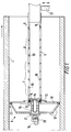
- a heated pipe 4 moves in the direction shown over a tube or lance 5 along which cooling water is propelled in the direction shown towards a terminal guide member 6.
- the lance has, on its outer surface, groups of grooves 7,8,9 each including a number of nozzles 10 inclined at various angles to the axis of the pipe in a direction such that the emerging water is projected towards the pipe surface with a major component of its velocity carrying it in the same direction as the axial movement of the pipe.
- the terminal guide cone has a solid front plate and conical outer surface 17 and a skeletal rear plate 18 through which the cone cooling water can escape.
- the exposed end of the extension piece 12 is reduced in diameter and slotted to house a cam lever 19 mounted on a pivot shaft 20.
- the cam is turned to lock a flat retaining key 21 against the shoulder of the extension piece thereby providing the means by which the terminal guide cone is retained on this extension piece.
- the cam lever and retaining key act as a quick release mechanism permitting easy changing of the terminal guide member when a large change in pipe diameters has to be accommodated.
- the lance is supplied with pressurised water, and the head of the lance is held approximately on the centre line of the advancing pipe by a support 22.
- the hot pipe advances, supported on skewed rollers (not shown) which give it a helical movement, i.e. advancing axially and rotating on its own axis simultaneously.
- the guide “cone” is used to assist entry of the fixed lance into the end of the advancing pipe.
- the action of the inclined jets of water is to quench the inner surface of the pipe and to propel the water along the inner wall at high speed in the same direction as the pipe's axial movement.
- the purpose of varying the angles at which the nozzle holes are drilled in the lance is to ensure that the water is accelerated throughout the quench area thus ensuring that it leaves the quench zone with sufficient velocity to ensure that it will flow clear of the pipe end without forming surges. Surges would result in pressure fluctuations at the start of the quench zone and cause leakage past the guide cone.
- the high velocity, closely spaced jets entrain part of the atmosphere within the pipe immediately behind the guide cone.
- the resultant drop in pressure in this area causes a flow of air, and/or products of combustion from the heating furnace, to be drawn through the gap 23 between the head of the guide cone and the bore of the pipe.
- the presence of this gap is essential to generate a relatively high velocity through the gap, thus preventing a reverse flow of cooling water, and at the same time preventing the formation of a vacuum high enough to impede the free flow of water along the pipe which would cause surging, steam entrapment and reverse flow conditions.
- FIG 2 there is illustrated a sealing collar 24, one or more of which can be slipped over the end of the lance after removing the extension piece 12.
- a sealing collar 24 By locating the sealing collar(s) in appropriate location(s) over selecting grooves, and locking them in position by locking screws 25 the spray pattern may be modified at will to meet variations in quenching requirements, e.g. the desired quenching profile for different steel compositions.
- the illustration shows the collar positioned over one groove only but it may be designed to cover several grooves. In all cases loss of water from the ends is prevented by the presence of resilient "O" rings 26 located in grooves in the inner surface of the collar.
- Figure 3 illustrates another method of modifying the flow pattern by first removing the extension piece and fitting a flanged sleeve 27 designed to cover one or more grooves at the end of the lance.
- This arrangement is less flexible but has the merit of more secure fixing by using screws 28 passing through holes drilled to match those in the flanged extension piece 12.
- a resilient "O" ring 29 located in a suitably sized groove will prevent leakage of water from the end of the flanged sleeve.
- the shape and size of the lance nozzles may be changed as also may the terminal guide member and its locking mechanisms.
- the groove/nozzle seals adopted may be different from that shown in Figures 2 and 3, e.g. a simple form of resilient "O" ring may be sited over a selected groove and clamped in position by a hose clip or the like.
Landscapes
- Chemical & Material Sciences (AREA)
- Engineering & Computer Science (AREA)
- Physics & Mathematics (AREA)
- Thermal Sciences (AREA)
- Crystallography & Structural Chemistry (AREA)
- Mechanical Engineering (AREA)
- Materials Engineering (AREA)
- Metallurgy (AREA)
- Organic Chemistry (AREA)
- Heat Treatment Of Articles (AREA)
Applications Claiming Priority (2)
| Application Number | Priority Date | Filing Date | Title |
|---|---|---|---|
| GB9106924 | 1991-04-03 | ||
| GB919106924A GB9106924D0 (en) | 1991-04-03 | 1991-04-03 | Hardening pipes |
Publications (2)
| Publication Number | Publication Date |
|---|---|
| EP0507619A2 true EP0507619A2 (de) | 1992-10-07 |
| EP0507619A3 EP0507619A3 (en) | 1993-10-06 |
Family
ID=10692544
Family Applications (1)
| Application Number | Title | Priority Date | Filing Date |
|---|---|---|---|
| EP19920302981 Withdrawn EP0507619A3 (en) | 1991-04-03 | 1992-04-03 | Hardening pipes |
Country Status (2)
| Country | Link |
|---|---|
| EP (1) | EP0507619A3 (de) |
| GB (1) | GB9106924D0 (de) |
Family Cites Families (3)
| Publication number | Priority date | Publication date | Assignee | Title |
|---|---|---|---|---|
| DE2105886A1 (de) * | 1971-02-01 | 1972-08-24 | Mannesmann Ag | Verfahren und Vorrichtung zum Abschreckhärten von Rohren |
| DE2137627C3 (de) * | 1971-07-28 | 1974-02-14 | Ludwig-Ofag-Indugas Industrieofenanlagen Gmbh, 4300 Essen | Vorrichtung zum Innenabschrecken von Rohren |
| JPS53724B2 (de) * | 1973-05-21 | 1978-01-11 |
-
1991
- 1991-04-03 GB GB919106924A patent/GB9106924D0/en active Pending
-
1992
- 1992-04-03 EP EP19920302981 patent/EP0507619A3/en not_active Withdrawn
Also Published As
| Publication number | Publication date |
|---|---|
| GB9106924D0 (en) | 1991-05-22 |
| EP0507619A3 (en) | 1993-10-06 |
Similar Documents
| Publication | Publication Date | Title |
|---|---|---|
| US8501083B2 (en) | Spray quench systems for heat treated metal products | |
| US4110092A (en) | Method of apparatus for cooling inner surface of metal pipe | |
| US4444556A (en) | Cooling apparatus | |
| CN109926215B (zh) | 经由涡轮发动机的壳中的孔输送修复涂层的喷射喷嘴装置 | |
| CA1065745A (en) | Method of quenching large-diameter thin-wall metal pipe | |
| US3807714A (en) | Apparatus for the quenching of pipe | |
| US4815523A (en) | Device and process for cleaning a recirculation-type regenerative heat exchanger | |
| US3671028A (en) | Quench system for pipes | |
| EP0507619A2 (de) | Verfahren und Vorrichtung zum Abschrecken von Rohren | |
| US3486554A (en) | Double walled tubular assemblage for cooling elongate material | |
| US6418732B1 (en) | Process and device for cooling extruded hollow sections | |
| US3208869A (en) | Fluidized coating of pipe | |
| JP3268240B2 (ja) | 酸素吹液体燃料バーナ | |
| US4210010A (en) | Cooling arrangement | |
| US3937449A (en) | Liquid-fuel atomization and injection device | |
| US20210387212A1 (en) | Cross Jet Cleaning Nozzle, Produced By Additive Manufacturing | |
| KR840001288Y1 (ko) | 관내 면도장 장치 | |
| JP4388499B2 (ja) | パイプの冷却設備および冷却方法 | |
| KR840002228B1 (ko) | 복수기에 있어서의 전열관 내면의 도장장치 | |
| US11498529B2 (en) | Apparatus and method for treating a vehicle surface with a fluid | |
| GB2176210A (en) | A method and apparatus for cooling an advancing elongate metal product | |
| JP2005007248A (ja) | 両輪型自動回転洗浄装置 | |
| JPH0615070B2 (ja) | 管内面ライニング方法 | |
| JPS60417B2 (ja) | 高温被処理材の冷却方法 | |
| JPH08189630A (ja) | スートブロワ |
Legal Events
| Date | Code | Title | Description |
|---|---|---|---|
| PUAI | Public reference made under article 153(3) epc to a published international application that has entered the european phase |
Free format text: ORIGINAL CODE: 0009012 |
|
| AK | Designated contracting states |
Kind code of ref document: A2 Designated state(s): AT BE CH DE DK ES FR GB GR IT LI LU MC NL PT SE |
|
| PUAL | Search report despatched |
Free format text: ORIGINAL CODE: 0009013 |
|
| AK | Designated contracting states |
Kind code of ref document: A3 Designated state(s): AT BE CH DE DK ES FR GB GR IT LI LU MC NL PT SE |
|
| 17P | Request for examination filed |
Effective date: 19940325 |
|
| RAP1 | Party data changed (applicant data changed or rights of an application transferred) |
Owner name: TUBULAR INDUSTRIES SCOTLAND LIMITED |
|
| STAA | Information on the status of an ep patent application or granted ep patent |
Free format text: STATUS: THE APPLICATION IS DEEMED TO BE WITHDRAWN |
|
| 18D | Application deemed to be withdrawn |
Effective date: 19961104 |