EP0506705B1 - Verfahren und apparat zur herstellung von filmen - Google Patents
Verfahren und apparat zur herstellung von filmen Download PDFInfo
- Publication number
- EP0506705B1 EP0506705B1 EP91900258A EP91900258A EP0506705B1 EP 0506705 B1 EP0506705 B1 EP 0506705B1 EP 91900258 A EP91900258 A EP 91900258A EP 91900258 A EP91900258 A EP 91900258A EP 0506705 B1 EP0506705 B1 EP 0506705B1
- Authority
- EP
- European Patent Office
- Prior art keywords
- film
- compartment
- barrier element
- barrier
- film formation
- Prior art date
- Legal status (The legal status is an assumption and is not a legal conclusion. Google has not performed a legal analysis and makes no representation as to the accuracy of the status listed.)
- Expired - Lifetime
Links
Images
Classifications
-
- B—PERFORMING OPERATIONS; TRANSPORTING
- B05—SPRAYING OR ATOMISING IN GENERAL; APPLYING FLUENT MATERIALS TO SURFACES, IN GENERAL
- B05D—PROCESSES FOR APPLYING FLUENT MATERIALS TO SURFACES, IN GENERAL
- B05D1/00—Processes for applying liquids or other fluent materials
- B05D1/18—Processes for applying liquids or other fluent materials performed by dipping
- B05D1/20—Processes for applying liquids or other fluent materials performed by dipping substances to be applied floating on a fluid
- B05D1/202—Langmuir Blodgett films (LB films)
- B05D1/206—LB troughs
-
- B—PERFORMING OPERATIONS; TRANSPORTING
- B82—NANOTECHNOLOGY
- B82Y—SPECIFIC USES OR APPLICATIONS OF NANOSTRUCTURES; MEASUREMENT OR ANALYSIS OF NANOSTRUCTURES; MANUFACTURE OR TREATMENT OF NANOSTRUCTURES
- B82Y30/00—Nanotechnology for materials or surface science, e.g. nanocomposites
-
- B—PERFORMING OPERATIONS; TRANSPORTING
- B82—NANOTECHNOLOGY
- B82Y—SPECIFIC USES OR APPLICATIONS OF NANOSTRUCTURES; MEASUREMENT OR ANALYSIS OF NANOSTRUCTURES; MANUFACTURE OR TREATMENT OF NANOSTRUCTURES
- B82Y40/00—Manufacture or treatment of nanostructures
Definitions
- the said amphiphilic compounds are oriented so that the water-soluble end of the compound is in the liquid phase and the fat-soluble end in the gas phase.
- LB-films attract nowadays great interest because they open new technical prospects e.g. in the semiconductor industry as resists, in data communication as photoconductors, in laser technique in the SHG formation as well as in the sensor technique.
- a problem has been that so far there has not been commercially available a so-called continuously operating LB-method and apparatus.
- the US Patent US-A-4,093,757 describes an apparatus and a method for depositing a monomolecular layer of an amphiphilic compound onto a substrate.
- the apparatus consists of two compartments and the compartments are separated by a horizontally rotatable cylinder partly immersed in the liquid and feeding molecules of the amphiphilic compound from one compartment to the other.
- the continuous deposition and production of the film is performed by adding dropwise, at a predetermined rate, a film compound, dissolved in an organic solvent, into one compartment and continuously transferring the said compound to the other compartment by rotating the cylinder.
- JP-A-62 274 732 describes apparatus for adhering two types of molecular layer to a substrate which uses a fixed barrier and a barrier rotatable about an axis.
- US Patents US-A-4,722,856 and US-A-4,783,348 describe an apparatus of another type for continuously producing films, wherein no moving mechanical components are used in contact with the film, but the film is compressed and transported from one region of the trough to another using a continuous medium flow, either by blowing gas above the liquid surface tangentially to the surface or by draining the surface from an upper level to a lower level and continuously adding the film compound to the upper compartment.
- a method and apparatus have now been invented that permit the continuous production of films by simple means, where the film is controllably deposited onto a substrate and where efficient deposition rates can be attained if desired, e.g. a rate of 30 m2/h.
- This is attainable by the method in accordance with the present invention for continuously producing a monomolecular film on a liquid surface in a trough for the deposition thereof onto a substrate, the surface area of the film being defined by a barrier element and the side walls of the trough, which method is characterized in that the barrier element, pivoted at one end to perform a horizontally rotating movement along the surface in a film formation compartment of the trough, gradually transfers the film, at a surface pressure suitable for deposition, to a deposition compartment of the trough connected to the film formation compartment over a connection zone, for the deposition of the film onto the substrate, and additional film forming substance is introduced to the surface of the liquid in the film formation compartment, on the opposite side of the said barrier element with respect to its rotational
- the moving barrier element gradually pushes the film from the film formation compartment of the trough to the said separate deposition compartment.
- the barrier element or specifically its radially outer end section, during its rotating movement, has reached the connection zone, the film will be almost completely transferred to the deposition compartment and at this point it will still be separated from the main body of the film formation compartment by the barrier element.
- the barrier element or specifically its radially outer end section, during its rotating movement, has reached the connection zone, the film will be almost completely transferred to the deposition compartment and at this point it will still be separated from the main body of the film formation compartment by the barrier element.
- the surface in the connection zone will join that of the film formation compartment, due to the further barrier element movement.
- the said barrier element will, at the point just prior to the joining of the films, due to the suitable design of the film formation compartment, extend both across the width of the trough in the connection zone and also intersect the film formation compartment, the barrier element thus being simultaneously in contact with the first mentioned film in the deposition zone and the newly formed film in the film formation compartment.
- the one and the same barrier element elastically moves the new film previously made in the film formation compartment to join the film already in the deposition compartment.
- the further movement of the barrier element then pushes this joined film gradually to the deposition station as it is used for deposition onto the substrate, all the time maintaining the required surface pressure in the film.
- one new film is formed to be transferred into the deposition compartment.
- the geometry of the trough and the barrier element has to be such that at the stage of establishing surface contact, as described above, when the barrier element rotates over an angle s, the change in surface area (dA1/ds) in the connection or deposition zone, has to be equal to or smaller than the change of surface area (dA2/ds) in the film formation compartment for compensation to take place.
- the speed of rotation of the barrier element at this stage has to be carefully controlled in order to maintain constant surface pressure.
- the first barrier element moves the film to the deposition compartment as the film is used, maintaining constant surface pressure
- the second barrier element together with the first mentioned barrier element together with the walls of the trough define an area of the film formation compartment wherein film forming substance is added to form a new film to be transferred by the said second barrier element to the deposition compartment after the first mentioned barrier element or rather its outer end has reached the connection zone and surface contact at this point has been established.
- barrier elements there are three barrier elements to be operated synchronously, whereby, at each stage of the film formation process, always one barrier element is substantially immobile, forming adjacent the connection zone a radially extending separation wall preventing film from slipping from the connection zone back into the film formation compartment and the two other barrier elements function as described above.
- the two other barrier elements function as described above.
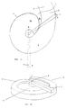
- the apparatus for continuously producing a monomolecular film at a liquid surface comprises a trough having walls and a rim for receiving the liquid and at least one horizontally rotatable barrier element mounted at one end on a vertical shaft or shafts and in contact with the liquid surface and resting on the rim of the trough, which barrier element together with the walls of the trough defines the surface area of the film to be formed, characterized in that the trough includes a film formation compartment and a deposition compartment for depositing the film onto a substrate, which deposition compartment joins the film formation compartment via a connection zone, and wherein the at least one barrier element is positionable to contact both a new film in the film formation compartment and a film formed during a previous cycle, to enable transfer of the previous cycle film from the film formation compartment through the connection zone into the deposition compartment, and to permit the films to contact each other and join in the connection zone.
- the apparatus of the invention comprises a two-compartment trough, namely a primary film formation compartment where the barrier element or the barrier elements are mounted at one end and where they perform their rotating movement, and a deposition compartment.
- the shape of the film formation compartment is substantially annular, the deposition compartment joining the film formation compartment substantially tangentially, the connection zone then being the area in the deposition zone lying immediately outside and adjacent the imaginary periphery of the annular film formation compartment.
- the film formation compartment may also have the shape of an open ring, or rather of a spiral or a hook, the outer extension of the spiral/hook connecting to the deposition compartment. The inner end part of the spiral/hook will then be physically separated from the deposition chamber.
- the barrier element or elements are mounted by one end in the middle of the ring or spiral.
- the film formation compartment is substantially shaped like a hooked U, whereby the mounting point of the barrier element or elements during their sweeping circular movement over the leg and the bottom parts of the U, moves back and forth substantially along a rectilinear path between the legs of the U.
- the deposition compartment joins to one leg of the U as an extension to the latter.
- the shape and size of the deposition region are not critical in regard to the invention, as long as it is large enough for allowing deposition of the film onto the substrate and for measuring the surface pressure.
- the film formation compartment is substantially circular, the barrier elements being rotatably and coaxially mounted on vertical axes in the centre of the circle and extending radially from the centre over the walls of the trough.
- the deposition compartment is advantageously connected to the film formation compartment substantially tangentially, whereby the connection zone of the said compartment will be the area on the outside of and immediately adjacent the imaginary periphery of the film formation compartment.
- this embodiment it is, however, preferable in this embodiment to use two independently mounted, but synchronously operated barrier elements, so that always one of the barrier elements is transferring a film for deposition, while a new film is being formed in the region defined by the said two barrier elements, subsequently to be joined as an extension to the previously formed film and then to be moved to the deposition compartment to enable continuous deposition onto the substrate.
- the barrier elements are in this case preferably constructed so that they diverge symmetrically from the centre outwards so that a barrier element can rest tightly against another barrier element acting as a separation wall, thus promoting the complete transfer of the film to the deposition compartment and making sure that the apparatus remains clean.
- the invention makes it possible to make and to transfer a two-dimensional film to be continuously deposited onto a substrate with a device that operates like a pump or bellows.
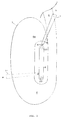
- the trough is shaped like a longitudinal U, comprising a film formation compartment 4 and a deposition compartment 5 and a connection zone 6 connecting these two.
- the most essential difference between this and the embodiment according to figure 1 is the path of the barrier 7 or its fastening point 8.
- the barrier is fixed at one end 8 to a conveyor or belt 9 which moves along a longitudinal path around two wheels 10 and 10'.
- the conveyor 9 can be any, for this purpose suitable conveyor, e.g. a chain conveyor, whereby the wheels 10, 10' may accordingly be toothed wheels or similar.
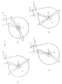
- the apparatus comprises three synchronously operated barrier elements or barriers 7a, 7b and 7c, the movement of which is controlled by means of the surface pressure measured in the deposition compartment 5.
- the trough is substantially circular and the barriers coaxially but independently mounted on a vertical shaft 8.
- the deposition compartment, or its one wall 11, is connected over the connection zone 6 substantially tangentially to the film formation compartment.
- the barrier 7a is moving a film in its rotating direction to the deposition compartment.
- barrier 7a Before the barrier 7a has reached the connection zone, film substance is added to the other side of the barrier 7a, onto the liquid surface in the surface area defined by the barriers 7a and 7b.
- the barrier 7c is during this cycle immobile acting as a separation wall adjacent the connection zone 6.
- the barrier 7a has already approached the connection zone and just established surface contact between this and the film formation compartment, and the barrier 7b has correspondingly moved a little forward to maintain the required surface pressure.
- the films on both sides of the barrier 7a are elastically joined at the correct surface pressure.
- the barrier 7a has passed over the connection zone to rest against the barrier 7c. Thus any film material between the barriers 7a and 7c is forced to move to the connection zone.
- the film forming substance is added to the liquid surface e.g. by a computer controlled liquid feeder.
- the point of the applicator touches the liquid-gas interface during the application.
- the point of the applicator is moved away from above the trough by a computer controlled electric motor, to leave room enough for the barrier movement.
Landscapes
- Engineering & Computer Science (AREA)
- Chemical & Material Sciences (AREA)
- Nanotechnology (AREA)
- Condensed Matter Physics & Semiconductors (AREA)
- Physics & Mathematics (AREA)
- General Physics & Mathematics (AREA)
- Crystallography & Structural Chemistry (AREA)
- Materials Engineering (AREA)
- Composite Materials (AREA)
- Manufacturing & Machinery (AREA)
- Coating Apparatus (AREA)
- Physical Or Chemical Processes And Apparatus (AREA)
- Application Of Or Painting With Fluid Materials (AREA)
- Materials For Medical Uses (AREA)
- Measuring Pulse, Heart Rate, Blood Pressure Or Blood Flow (AREA)
- Piezo-Electric Transducers For Audible Bands (AREA)
- Underground Structures, Protecting, Testing And Restoring Foundations (AREA)
Claims (9)
- Verfahren zum kontinuierlichen Herstellen eines monomolekularen Films auf einer Flüssigkeitsoberfläche in einer Wanne (2) zu dessen Ablagerung auf ein Substrat, wobei die Oberfläche des Films durch ein Barrierenelement (7) und die Seitenwände (3) der Wanne begrenzt ist, dadurch gekennzeichnet` daß das Barrierenelement, das an einem Ende geschwenkt wird, um eine waagerechte Drehbewegung an der Oberfläche in einer Filmbildungskammer (4) der Wanne entlang zu vollführen, nach und nach den Film mit einem zur Ablagerung geeigneten Oberflächendruck zu einer mit der Filmbildungskammer über eine Verbindungszone (6) verbundenen Ablagerungskammer (5) zur Ablagerung des Films auf das Substrat transportiert und zusätzliche Filmbildungssubstanz auf die Oberfläche der Flüssigkeit in der Filmbildungskammer auf der zu seiner Drehrichtung gegenüberliegenden Seite des Barrierenelements zur Bildung eines neuen Films eingeleitet wird, wobei der neue Film, wenn das radiale Außenende des Barrierenelements infolge seiner weiteren Drehbewegung die Verbindungszone erreicht und die Herstellung einer Oberflächehberührung zwischen der Filmbildungs- und Ablagerungskammer ermöglicht hat, mit dem erforderlichen Oberflächendruck durch ein Barrierenelement transportiert wird, um sich mit dem erstgenannten Film zu vereinigen, der bereits zur Ablagerungskammer transportiert wurde.
- Verfahren nach Anspruch 1, dadurch gekennzeichnet, daß sich das schwenkende des Barrierenelements auf einem im wesentlichen längs verlaufenden Weg bewegt, wenn das Barrierenelement seine Drehbewegung vollführt.
- Verfahren nach Anspruch 1 oder 2, dadurch gekennzeichnet, daß nur ein Barrierenelement vorhanden ist, das in mindestens einer Position während seiner Drehbewegung mit dem Film sowohl in der Filmbildungskammer als auch in dar Verbindungszone in Berührung steht.
- Verfahren nach einem der Ansprüche 1 bis 3, dadurch gekennzeichnet, daß die gemeinsamen Umdrehungsgeschwindigkeiten der Barrierenelemente auf der Grundlage des in der Ablagerungsregion gemessenen Oberflächendrucks geregelt werden.
- Vorrichtung zum kontinuierlichen Herstellen eines monomolekularen Films auf einer Flüssigkeitsoberfläche, wobei die Vorrichtung aufweist: eine Wanne (2) mit Wänden und einem Rand (3) zum Aufnehmen der Flüssigkeit und mindestens ein waagerecht drehbares Barrierenelement (7), das an einem Ende an einer senkrechten Welle oder Wellen (8, 10, 10') angebracht ist, mit der Flüssigkeitsoberfläche in Berührung steht und auf dem Rand (3) der Wanne ruht, und das Barrierenelement zusammen mit den Wänden der Wanne die Oberfläche des zu bildenden Films begrenzt,
dadurch gekennzeichnet, daß die Wanne eine Filmbildungskammer (4) und eine Ablagerungskammer (5) zum Ablagern des Films auf ein Substrat aufweist, wobei die Ablagerungskammer an die Filmbildungskammer (4) über eine Verbindungszone (6) anschließt und das mindestens eine Barrierenelement (7, 7', 7a bis 7c) so positionierbar ist, daß es sowohl einen neuen Film in der Filmbildungskammer als auch einen während eines vorhergehenden Zyklus gebildeten Film berührt, damit der Film des vorhergehenden Zyklus aus der Filmbildungskammer über die Verbindungszone (6) in die Ablagerungskammer (5) transportiert werden kann und damit sich die Filme berühren und in der Verbindungszone (6) vereinigen können. - Vorrichtung nach Anspruch 5, dadurch gekennzeichnet, daß die Filmbildungskammer (4) im wesentlichen U-förmig ist und ein Ende des Barrierenelements an einem Punkt angebracht ist, der sich während der Drehbeweguhg des Barrierenelements auf einem im wesentlichen längs verlaufenden Weg zwischen den Schenkeln des U hin- und herbewegt.
- Vorrichtung nach Anspruch 5, dadurch gekennzeichnet, daß die Filmbildungskammer im wesentlichen spiralförmig ist und ein einzelnes Barrierenelement aufweist, das in mindestens einer seiner Positionen sowohl die Breite der Filmbildungskammer (4), insbesondere ihr Endteil (4a), als auch die Verbindungszone (6) überstreicht.
- Vorrichtung nach Anspruch 5, dadurch gekennzeichnet, daß die Filmbildungskammer im wesentlichen ringförmig ist und mindestens zwei Barrierenelemente aufweist, die unabhängig und gleichachsig angebracht sind, wobei in jedem Stadium des Filmbildungsprozesses eines der Barrierenelemente (7a) zusammen mit den Wänden der Ablagerungskammer und der Verbindungszone die Oberfläche des auf das Substrat abzulagernden Films abgrenzt und das andere Barrierenelement (7b) zusammen mit dem erstgenannten Barrierenelement (7a) in der Filmbildungskammer die Oberfläche des anschließend auf das Substrat abzulagernden Films abgrenzt.
- Vorrichtung nach Anspruch 8, dadurch gekennzeichnet, daß die Filmbildungskammer drei Barrierenelemente (7a, 7b, 7c) aufweist, von denen eines (7c) in jedem Stadium des Filmbildungsprozesses unbeweglich ist.
Applications Claiming Priority (3)
| Application Number | Priority Date | Filing Date | Title |
|---|---|---|---|
| FI896068A FI87628C (fi) | 1989-12-19 | 1989-12-19 | Foerfarande och anordning foer framstaellning av filmer |
| FI896068 | 1989-12-19 | ||
| PCT/FI1990/000298 WO1991008841A1 (en) | 1989-12-19 | 1990-12-14 | Method and apparatus for producing films |
Publications (2)
| Publication Number | Publication Date |
|---|---|
| EP0506705A1 EP0506705A1 (de) | 1992-10-07 |
| EP0506705B1 true EP0506705B1 (de) | 1995-07-05 |
Family
ID=8529536
Family Applications (1)
| Application Number | Title | Priority Date | Filing Date |
|---|---|---|---|
| EP91900258A Expired - Lifetime EP0506705B1 (de) | 1989-12-19 | 1990-12-14 | Verfahren und apparat zur herstellung von filmen |
Country Status (8)
| Country | Link |
|---|---|
| US (1) | US5300329A (de) |
| EP (1) | EP0506705B1 (de) |
| JP (1) | JPH05502821A (de) |
| AT (1) | ATE124635T1 (de) |
| CA (1) | CA2071857A1 (de) |
| DE (1) | DE69020744D1 (de) |
| FI (1) | FI87628C (de) |
| WO (1) | WO1991008841A1 (de) |
Families Citing this family (1)
| Publication number | Priority date | Publication date | Assignee | Title |
|---|---|---|---|---|
| US5558845A (en) * | 1994-07-27 | 1996-09-24 | Georgia Tech Research Corp. | Film pump for applying a monolayer film over water surfaces |
Family Cites Families (4)
| Publication number | Priority date | Publication date | Assignee | Title |
|---|---|---|---|---|
| FR2341199A1 (fr) * | 1976-02-11 | 1977-09-09 | Commissariat Energie Atomique | Procede et dispositif de formation et de depot sur un substrat de couches monomoleculaires de molecules amphiphiles |
| GB8417959D0 (en) * | 1984-07-14 | 1984-08-15 | Nima Technology Ltd | Barrier system |
| US4722856A (en) * | 1986-01-02 | 1988-02-02 | Molecular Electronics Corporation | Method and apparatus for depositing monomolecular layers on a substrate |
| US5044308A (en) * | 1988-02-18 | 1991-09-03 | Fatemeh Mojtabaj | Device and method for fluorescence microscopic controlled formation of monomolecular layers of organic films |
-
1989
- 1989-12-19 FI FI896068A patent/FI87628C/fi not_active IP Right Cessation
-
1990
- 1990-12-14 CA CA002071857A patent/CA2071857A1/en not_active Abandoned
- 1990-12-14 US US07/861,961 patent/US5300329A/en not_active Expired - Fee Related
- 1990-12-14 AT AT91900258T patent/ATE124635T1/de not_active IP Right Cessation
- 1990-12-14 DE DE69020744T patent/DE69020744D1/de not_active Expired - Lifetime
- 1990-12-14 EP EP91900258A patent/EP0506705B1/de not_active Expired - Lifetime
- 1990-12-14 WO PCT/FI1990/000298 patent/WO1991008841A1/en not_active Ceased
- 1990-12-14 JP JP3500967A patent/JPH05502821A/ja active Pending
Also Published As
| Publication number | Publication date |
|---|---|
| FI87628B (fi) | 1992-10-30 |
| CA2071857A1 (en) | 1991-06-20 |
| US5300329A (en) | 1994-04-05 |
| ATE124635T1 (de) | 1995-07-15 |
| FI87628C (fi) | 1993-02-10 |
| WO1991008841A1 (en) | 1991-06-27 |
| EP0506705A1 (de) | 1992-10-07 |
| JPH05502821A (ja) | 1993-05-20 |
| DE69020744D1 (de) | 1995-08-10 |
| FI896068A0 (fi) | 1989-12-19 |
Similar Documents
| Publication | Publication Date | Title |
|---|---|---|
| US4722856A (en) | Method and apparatus for depositing monomolecular layers on a substrate | |
| AU735039B2 (en) | Method for dispensing of powders | |
| KR100870627B1 (ko) | 스패터링 장치 | |
| JP2003508246A (ja) | 高速プロトタイピング技術および装置、ならびに高速プロトタイピングによって作製された三次元部品 | |
| EP0506705B1 (de) | Verfahren und apparat zur herstellung von filmen | |
| US6318112B1 (en) | Apparatus for coating liquids onto core pieces | |
| US5512326A (en) | Method and apparatus for forming monomolecular film or built-up monomolecular film | |
| CN116477144A (zh) | 一种具有调整结构的罐装食品罐装机构 | |
| KR100508454B1 (ko) | 3차원 형상에 균일한 코팅을 위한 분무코팅 장치 및 방법 | |
| US5419464A (en) | Apparatus and process for dispensing food materials | |
| Nitsch et al. | Convective monolayer compression in channel flow: Behaviour and transfer of soluble and insoluble films | |
| US4785762A (en) | Apparatus for forming film | |
| JP2003525183A (ja) | インラインカムを備える回転移送装置 | |
| EP0192517A1 (de) | Dosiervorrichtung, insbesondere für Nahrungsprodukte | |
| JPH06260417A (ja) | 半導体素子製造用スパッタリング装置 | |
| KR101333514B1 (ko) | 분말 연속공급장치 | |
| JP4033515B2 (ja) | 回転円盤固体培養装置の培養原料盛込方法及び装置 | |
| JP3004824U (ja) | 流体塗布装置 | |
| JP3015383U (ja) | カップ型タルト成形機 | |
| JPH01228539A (ja) | 累積膜形成方法 | |
| JPS61278374A (ja) | Lb膜作成方法 | |
| JPH1087055A (ja) | 物品移送装置 | |
| JPH1087056A (ja) | 物品移送装置及びこれに用いられる運動機構 | |
| AU2007329186A1 (en) | Method and apparatus for providing a product with a desired surface finish | |
| KR200358071Y1 (ko) | 골재이송장치 |
Legal Events
| Date | Code | Title | Description |
|---|---|---|---|
| PUAI | Public reference made under article 153(3) epc to a published international application that has entered the european phase |
Free format text: ORIGINAL CODE: 0009012 |
|
| 17P | Request for examination filed |
Effective date: 19920618 |
|
| AK | Designated contracting states |
Kind code of ref document: A1 Designated state(s): AT BE CH DE DK ES FR GB GR IT LI LU NL SE |
|
| 17Q | First examination report despatched |
Effective date: 19940308 |
|
| GRAA | (expected) grant |
Free format text: ORIGINAL CODE: 0009210 |
|
| AK | Designated contracting states |
Kind code of ref document: B1 Designated state(s): AT BE CH DE DK ES FR GB GR IT LI LU NL SE |
|
| PG25 | Lapsed in a contracting state [announced via postgrant information from national office to epo] |
Ref country code: IT Free format text: LAPSE BECAUSE OF FAILURE TO SUBMIT A TRANSLATION OF THE DESCRIPTION OR TO PAY THE FEE WITHIN THE PRE;WARNING: LAPSES OF ITALIAN PATENTS WITH EFFECTIVE DATE BEFORE 2007 MAY HAVE OCCURRED AT ANY TIME BEFORE 2007. THE CORRECT EFFECTIVE DATE MAY BE DIFFERENT FROM THE ONE RECORDED.SCRIBED TIME-LIMIT Effective date: 19950705 Ref country code: GR Free format text: LAPSE BECAUSE OF FAILURE TO SUBMIT A TRANSLATION OF THE DESCRIPTION OR TO PAY THE FEE WITHIN THE PRESCRIBED TIME-LIMIT Effective date: 19950705 Ref country code: NL Free format text: LAPSE BECAUSE OF NON-PAYMENT OF DUE FEES Effective date: 19950705 Ref country code: FR Effective date: 19950705 Ref country code: ES Free format text: THE PATENT HAS BEEN ANNULLED BY A DECISION OF A NATIONAL AUTHORITY Effective date: 19950705 Ref country code: BE Effective date: 19950705 Ref country code: AT Effective date: 19950705 Ref country code: DK Effective date: 19950705 Ref country code: LI Effective date: 19950705 Ref country code: CH Effective date: 19950705 |
|
| REF | Corresponds to: |
Ref document number: 124635 Country of ref document: AT Date of ref document: 19950715 Kind code of ref document: T |
|
| REF | Corresponds to: |
Ref document number: 69020744 Country of ref document: DE Date of ref document: 19950810 |
|
| PG25 | Lapsed in a contracting state [announced via postgrant information from national office to epo] |
Ref country code: SE Effective date: 19951005 |
|
| PG25 | Lapsed in a contracting state [announced via postgrant information from national office to epo] |
Ref country code: DE Effective date: 19951006 |
|
| REG | Reference to a national code |
Ref country code: CH Ref legal event code: PL |
|
| EN | Fr: translation not filed | ||
| PG25 | Lapsed in a contracting state [announced via postgrant information from national office to epo] |
Ref country code: GB Effective date: 19951214 |
|
| PG25 | Lapsed in a contracting state [announced via postgrant information from national office to epo] |
Ref country code: LU Free format text: LAPSE BECAUSE OF NON-PAYMENT OF DUE FEES Effective date: 19951231 |
|
| NLV1 | Nl: lapsed or annulled due to failure to fulfill the requirements of art. 29p and 29m of the patents act | ||
| PLBE | No opposition filed within time limit |
Free format text: ORIGINAL CODE: 0009261 |
|
| STAA | Information on the status of an ep patent application or granted ep patent |
Free format text: STATUS: NO OPPOSITION FILED WITHIN TIME LIMIT |
|
| 26N | No opposition filed | ||
| GBPC | Gb: european patent ceased through non-payment of renewal fee |
Effective date: 19951214 |