EP0506535B1 - Verfahren und Einrichtung zur Bearbeitung von Vorechos eines mittels einer Frequenztransformation kodierten digitalen Audiosignals - Google Patents
Verfahren und Einrichtung zur Bearbeitung von Vorechos eines mittels einer Frequenztransformation kodierten digitalen Audiosignals Download PDFInfo
- Publication number
- EP0506535B1 EP0506535B1 EP92400775A EP92400775A EP0506535B1 EP 0506535 B1 EP0506535 B1 EP 0506535B1 EP 92400775 A EP92400775 A EP 92400775A EP 92400775 A EP92400775 A EP 92400775A EP 0506535 B1 EP0506535 B1 EP 0506535B1
- Authority
- EP
- European Patent Office
- Prior art keywords
- module
- sample
- noise
- samples
- coding
- Prior art date
- Legal status (The legal status is an assumption and is not a legal conclusion. Google has not performed a legal analysis and makes no representation as to the accuracy of the status listed.)
- Expired - Lifetime
Links
- 238000000034 method Methods 0.000 title claims description 56
- 238000012545 processing Methods 0.000 title claims description 24
- 238000002592 echocardiography Methods 0.000 title description 25
- 230000005236 sound signal Effects 0.000 title description 8
- 238000001914 filtration Methods 0.000 claims description 62
- 230000007704 transition Effects 0.000 claims description 49
- 230000005540 biological transmission Effects 0.000 claims description 27
- 239000011159 matrix material Substances 0.000 claims description 9
- 230000009466 transformation Effects 0.000 claims description 9
- 230000003044 adaptive effect Effects 0.000 claims description 6
- 239000000654 additive Substances 0.000 claims description 5
- 230000000996 additive effect Effects 0.000 claims description 5
- 238000011156 evaluation Methods 0.000 claims description 5
- 238000013139 quantization Methods 0.000 claims description 5
- 238000000638 solvent extraction Methods 0.000 claims 1
- 230000008569 process Effects 0.000 description 15
- 238000004364 calculation method Methods 0.000 description 10
- 230000009467 reduction Effects 0.000 description 8
- 238000011002 quantification Methods 0.000 description 5
- 230000002441 reversible effect Effects 0.000 description 5
- 238000001228 spectrum Methods 0.000 description 5
- 238000001514 detection method Methods 0.000 description 4
- 238000010586 diagram Methods 0.000 description 3
- 230000002123 temporal effect Effects 0.000 description 3
- 230000015556 catabolic process Effects 0.000 description 2
- 238000004891 communication Methods 0.000 description 2
- 238000006731 degradation reaction Methods 0.000 description 2
- 238000000605 extraction Methods 0.000 description 2
- 230000000873 masking effect Effects 0.000 description 2
- 230000000694 effects Effects 0.000 description 1
- 230000008030 elimination Effects 0.000 description 1
- 238000003379 elimination reaction Methods 0.000 description 1
- 230000006870 function Effects 0.000 description 1
- 230000006872 improvement Effects 0.000 description 1
- 230000004048 modification Effects 0.000 description 1
- 238000012986 modification Methods 0.000 description 1
- 244000045947 parasite Species 0.000 description 1
- 230000001373 regressive effect Effects 0.000 description 1
- 238000005070 sampling Methods 0.000 description 1
- 238000007493 shaping process Methods 0.000 description 1
- 230000008054 signal transmission Effects 0.000 description 1
- 230000003595 spectral effect Effects 0.000 description 1
Images



Classifications
-
- H—ELECTRICITY
- H03—ELECTRONIC CIRCUITRY
- H03H—IMPEDANCE NETWORKS, e.g. RESONANT CIRCUITS; RESONATORS
- H03H17/00—Networks using digital techniques
- H03H17/02—Frequency selective networks
- H03H17/0248—Filters characterised by a particular frequency response or filtering method
- H03H17/0255—Filters based on statistics
- H03H17/0257—KALMAN filters
-
- H—ELECTRICITY
- H04—ELECTRIC COMMUNICATION TECHNIQUE
- H04B—TRANSMISSION
- H04B1/00—Details of transmission systems, not covered by a single one of groups H04B3/00 - H04B13/00; Details of transmission systems not characterised by the medium used for transmission
- H04B1/66—Details of transmission systems, not covered by a single one of groups H04B3/00 - H04B13/00; Details of transmission systems not characterised by the medium used for transmission for reducing bandwidth of signals; for improving efficiency of transmission
Definitions
- the invention relates to a method and a system for processing the pre-echoes of an audio-digital signal coded by frequency transform.
- Very sophisticated techniques such as the coding of these signals by frequency transform, such as transformed into modified discrete cosine, TCDM, are used in order to decrease the resulting bit rate of information, while preserving appreciably the quality of the original signal .
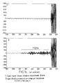
- the coding by transform proceeds by cutting up the time signal, succession of samples x (n), into blocks comprising N samples. On each of the aforementioned blocks, after application of a space-time amplitude weighting window, such as the window of block m on the samples 0 to N-1 as shown in FIG.
- the coding noise resulting from the quantification of the coefficients is distributed uniformly over the duration of the sample block.
- this block contains a non-stationarity, such as a sudden attack, as shown in FIG. 1b, the frequency spectrum of the signal, that is to say the distribution of the amplitude of the coefficients y (k) obtained after transform frequency, depending on the frequency f is almost flat.
- the aforementioned coding algorithms generally perform a spectral shaping of the noise (cf. publication of Johnston aforementioned) and, even with respect to the block containing a transition, as mentioned above, the noise spectrum is almost flat and a constant level for the duration of the block.
- the two blocks preceding the transition are affected by the phenomenon of N / 2 samples between successive windows. pre-echoes.
- the present invention relates to the implementation of a method and a system for processing the pre-echoes of a audio-digital signal encoded by TCDM transform in which the pre-echoes are substantially suppressed.
- Another object of the present invention is the implementation of a method and a system for processing the pre-echoes of an audio-digital signal coded by TCDM transform in which no modification of the signal levels, before or after attack, not being carried out, a quasi-perfect reconstruction of the signal after decoding is thus obtained.
- the method for processing the pre-echoes of an audio-digital signal coded by frequency transform, object of the present invention is remarkable in that it consists, after coding of this signal x (n) by frequency transform into coefficients y (k), on weighting windows formed on blocks of samples comprising N samples x ( n) successive, to be performed at the decoding of the transform coefficients y (k), an optimal filtering so as to reduce, when there is a transition or amplitude variation of the signal, the additive noise resulting during the coding of the quantification of the transform coefficients.
- the system for processing the pre-echos of filtering an audio-digital signal coded by frequency transform, object of the present invention comprising, on the one hand, arranged in cascade at the level of the coder a module for reading the samples x ( n) of an audio-digital signal constituting the latter into blocks of N samples, a TCDM transform calculation module delivering, from said sample blocks, corresponding transform coefficients y (k) and a quantization coding module of these coefficients with a view to their transmission via a transmission channel, and, on the other hand, arranged in cascade at the level of the decoder, upon reception of the transmission channel, a module for decoding the coefficients y (k ) and a module for calculating the inverse transform TCDM ⁇ 1, these modules constituting the decoder and delivering a noisy decoded signal x ′ (n), is remarkable in that it further comprises, on the one hand, at the level of the encoder, a module for detecting transitions identified by the rank Nq of the rank N
- the method and the system which are the subject of the present invention find application in the transmission of audio-digital signals, of high fidelity quality, in the transmission, coding, decoding of audio-digital signals, in all the applications of signal transmission.
- audio-digital such as the integrated digital network of ISDN services.
- the method comprises steps of coding the digital audio signal x (n), these samples being, by a process of reading the samples conformed as a block, denoted x (n), these blocks comprising for example N successive samples , each block being subjected to a weighting window formed on these -blocks, as shown for example in FIG.
- the above-mentioned blocks are then subjected to a TCDM transform processing, this transformation delivering the transform coefficients y (k).
- the aforementioned transform coefficients are then subjected to a coding process denoted H, this coding process delivering coded transform coefficients Cy (k) intended to be transmitted to and for a decoding process.
- the method which is the subject of the present invention consists in carrying out, at the decoding of the transform coefficients y (k), this decoding process being noted H ⁇ 1 at the level of the decoding proper, and more particularly following an inverse transformation process noted TCDM ⁇ 1 applied to the transform coefficients y (k) to obtain the samples x ′ (n) of rank n of the noisy decoded signal, an optimal filtering of these samples of the noisy decoded signal so as to reduce, during the presence of an amplitude transition of the audio-digital signal, the additive noise resulting during the coding of the quantization of the transform coefficients.
- the presence of the pre-echoes at the level of the coded audio-digital signal is in fact due to the degradation of the signal preceding the transition by the introduction of an additive noise b (n) resulting from the quantification of the transform coefficients y (k).
- the treatment and reduction of this phenomenon in accordance with the object of the method according to the present invention, is comparable to a problem of denoising which can be carried out by means of an optimal filtering of the decoded audio-digital signal.
- the method which is the subject of the present invention generally involves, at the coding level, a process of identifying the transition.
- Such an identification can be carried out in a nonlimiting manner by the detection of such a transition in the current block considered, by the creation for example of a variable t representative of the existence or non-existence of such a transition in the aforementioned block.
- the identification of the transition in the current block considered may be carried out by discriminating the position of the transition in the aforementioned block, that is to say in fact from the abscissa M of the sample representative of the first occurrence of this transition.
- the method which is the subject of the present invention also involves the evaluation of an energy parameter of each of the samples x (n), this energy parameter for each of the samples x (n) of the aforementioned audio-digital signal being noted ⁇ 2x (n).
- a particularly advantageous implementation of the process which is the subject of the invention can be carried out taking into account the fact that the additive noise b (n) is not stationary. Indeed, the energy of the aforementioned noise is higher for n close to the transition in the block considered than for the samples located at the beginning of the block.
- a particularly advantageous implementation of the method which is the subject of the present invention consists in carrying out the optimal filtering previously mentioned in the form of a KALMAN filtering.
- the KALMAN filtering performed during decoding then makes it possible, in accordance with the method of the present invention, to obtain the reduction of the phenomenon of pre-echoes in a particularly satisfactory manner, as will be described below in the description.
- the state model is associated with the original signal x (n) while the observation equation describes the decoded signal x ′ (n) noisy, that is to say affected by the pre-echoes.
- the equation of state can be defined in self-regressive form of order p.
- the value of p must be chosen so as to ensure a compromise between sufficiently precise modeling of the series of samples of the audio-digital signal x (n) and a volume and a limited computational load to ensure compatible processing in real time.
- a1 and a2 denote the prediction coefficients of the filter and w (n) denotes the amplitude of the innovation noise for the sample x (n) of rank n considered.
- x (n) naturally designates the original digital audio signal, that is to say the current order n sample considered
- b (n) designates the amplitude of the coding or preecho noise for this same sample
- x ′ (n) denotes the sample of rank n of the noisy decoded signal, that is to say the sample obtained on decoding, as shown in FIG. 2 after inverse transformation TCDM ⁇ 1.
- ⁇ 2b (n) denotes the energy of the coding noise and ⁇ 2w (n) the energy of the innovation noise w (n) for the sample x (n) of rank n considered.
- the method according to the invention then consists, during the coding process, in transmitting to the decoding level the value of the aforementioned energy parameters ⁇ 2x (n) and of existence of the transition as described above.
- the method which is the subject of the present invention consists, during the decoding process, of estimating the filtering parameters, that is to say the prediction coefficients a1, a2 of the filtering from the samples of the block b-1 preceding, in accordance to the relationships previously given in the description.
- the energies of coding noise ⁇ 2b (n) and of noise ⁇ 2w (n) for the sample of rank n considered are evaluated which makes it possible to ensure, at the decoding level, adaptive filtering of the KALMAN filtering type. of the noisy decoded signal x ′ (n) to reconstruct the filtered decoded signal in which the pre-echoes are substantially suppressed.
- t takes the value 0 or 1 as a function of the absence respectively of the presence of a transition for the current block considered.
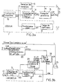
- FIGS. 3a representing more particularly an encoder and 3b representing on the contrary a decoder constituting the system according to the invention.
- FIGS. 3a and 3b are shown in the form of block diagrams, the various block diagrams making it possible to carry out the steps of the method which is the subject of the present invention as carried out in FIG. 2.
- the system comprises, on the one hand, arranged in cascade at the level of the encoder 1, a module 10 for reading samples x (n) of audio signal numerical constituting the latter in block of N samples, a module 11 for calculating the TCDM transform delivering from the sample blocks the corresponding transform coefficients y (k) and a module 12 for coding by quantification of these coefficients with a view to their transmission via a digital transmission channel denoted CT in FIG. 3a.
- the digital transmission channel CT will not be described in detail since it corresponds to a conventional type transmission channel.
- the system according to the invention comprises, on the other hand, arranged in cascade at the level of the decoder 2 and on reception of the aforementioned transmission channel CT a decoding module 20 coefficients y (k) and a module 21 for calculating the inverse transform TCDM ⁇ 1, these modules constituting the decoder and delivering a noisy decoded signal x ′ (n).
- the system further comprises, at the level of the coder 1, a module 13 for detecting the transitions identified by the rank Nq of the transition in the current block considered and a module 14 for extracting from the blocks of samples x (n) from the energy parameters ⁇ 2x (n) of the sample x (n) corresponding current or from a group of successive samples of the original signal.
- a coding module 15 is provided on the basis of the energy parameters ⁇ 2x (n) of the sample x (n) or of the group of samples of the sample block, this coding module making it possible to generate codes. corresponding C ⁇ 2x (n) and C, M in order to allow the coded transmission of the aforementioned parameters and of the signal indicator t of the presence of a transition in the current block via the transmission channel CT.
- transition detection module 13 As regards the previously mentioned transition detection module 13, it will simply be indicated that this generates the indicator t which takes for example the value 1 in the case of a block comprising a transition, that is to say say likely to generate pre-echoes, this indicator being simply coded on one bit and transmitted to the decoder.
- the module 13 also delivers the position of the transition in the block considered, that is to say the abscissa of the aforementioned point M.
- the address of the transition, M is then delivered to the coding module 15 previously mentioned and coded for example on log2 (N) bits where N is the size of the transform block for transmission in the form of the code C, M previously mentioned. .
- the detection of the attacks can be carried out by examining the temporal waveform, for example comparison of the value of the amplitude of the sample considered with a threshold value in the report 4 previously mentioned, the module 13 detection of course receiving the samples x (n) of the block considered.
- the system according to the invention comprises at decoder level 2 a module 22 for reconstituting the energy parameters transmitted, this module receiving from the transmission channel CT the codes d transition address C, M and of energy C ⁇ 2x (n) and delivers the corresponding parameters of address M and energy ⁇ 2x (n). It will be noted that the module 22 makes it possible to reconstruct the parameters essential for filtering and which are unknown at the level of the decoder.
- a module 23 for extracting the filtering parameters a1, a2 is provided before carrying out the evaluation of these parameters from the samples x (n) of the preceding block of samples and d evaluation of the energies of the coding noise ⁇ 2b (n) and of the noise ⁇ 2w (n) for the sample of rank n considered.
- the extraction of the aforementioned filtering parameters can be carried out either from the noisy decoded signal x ′ (n) or from the quantized transform coefficients y ′ (k) delivered by the decoding module 20.
- a KALMAN filtering module 20 which receives the noisy decoded signal x ′ (n) as a filtering input delivered by the reverse transformation module 21 TCDM ⁇ 1, this same filtering module 24 receiving the parameters as command input. filtering a1, a2 and evaluating the energies of the coding noise ⁇ 2b (n) and of the noise ⁇ 2w (n) delivered by the module 23 for extracting the aforementioned parameters.
- the filter module 20 receives the reconstituted energy parameters delivered by the module 22 and the address of the transition M.
- the filter module 20 outputs the filtered decoded signal xr (n).
- the decoder includes at the output a controlled switch 25 which receives, on the one hand, on a first switching input, the filtered decoded signal xr (n) and on a second switching input the signal x ′ (n) delivered by the decoder and more particularly by the reverse transformation module 21.
- the controlled switch 25 receives the indicator presence of transition t.
- the signal S delivered corresponds to that indicated in connection with FIG. 2.
- module 23 for extracting the filtering parameters a1, a2 and for evaluating the coding noise energies ⁇ 2b (n) and the noise ⁇ 2w (n) will be given in connection with FIG. 4.
- the module 23 for extracting the aforementioned filtering parameters comprises in parallel on an input port of the samples x ′ (n) of the noisy decoded signal a first channel A for calculating the filtering parameters a1 , a2 and noise ⁇ 2w (n) for the sample of rank n considered and a second channel B for calculating the coding noise ⁇ 2b (n).
- the filter parameters a1, a2 of the noise ⁇ 2w (n) and of the coding noise ⁇ 2b (n) are supplied to the filter module of KALMAN 24.
- the structure of the module 23 for extracting the filtering parameters as shown in FIG. 4a can be justified in the following manner.
- equation (1) requires knowledge of the prediction coefficients ai, i.e. a1, a2, when this equation of state is defined in self-regressive form of order 2 .
- the first channel A for calculating the filtering parameters comprises a sample memory 230 receiving the noisy samples x ′ (n) delivered by the module 21 for reverse transformation.
- the last R samples are kept in memory at the memory 230.
- These R samples serve as input to the device for calculating the prediction coefficients.
- the first channel A consequently includes a circuit 231 for calculating the prediction coefficients ai or more precisely a1, a2 and the prediction gain Gp.
- the calculation circuit 231 can for example be constituted by a digital calculation circuit allowing the calculation of the abovementioned coefficients by means of a Levinson algorithm.
- the aforementioned Levinson algorithm will not be described since this algorithm is known from the state of the art.
- the prediction coefficients a1, a2 or more generally ai constitute one of the inputs of the filtering module 24. These coefficients are assumed to be constant over the duration of the pre-echo.
- the first channel A comprises in cascade with the circuit 231 for calculating the prediction and prediction gain coefficients Gp a circuit 232 for calculating the variance of the innovation noise ⁇ 2w (n).
- This circuit receives on the one hand the reconstituted value of the energy parameter of the sample ⁇ 2x ′ (n) transmitted delivered by the corresponding module 22 and the prediction gain Gp.
- ⁇ 2x (n) is the energy of the original noiseless audio-digital signal, G p representing the prediction gain associated with the autoregressive model.
- the calculation of the gain G p can be carried out at the circuit 231 from the prediction coefficients a1 and a2 or more generally ai.
- a usable calculation method is described by Jayant and Noll in the Digital Coding of Waveforms 1984, Prentice Hall Signal Processing Series page 263.
- the second channel B comprises successively connected in cascade a circuit 233 for calculating the energy parameter ⁇ 2x ′ (n) of the sample x ′ (n) noisy.
- the calculation circuit 233 is followed by a circuit 235 for calculating the coding noise parameter ⁇ 2b (n) of the samples.
- the energy of the coding noise ⁇ 2b (n) can be deduced from the energies of the noiseless signals of origin ⁇ 2x (n) and of the noisy signal ⁇ 2x ′ (n) of the noisy signal x ′ (n).
- a is a constant between 0 and 1 and can for example be taken equal to 0.95.
- the calculation circuit 233 is associated with a delay circuit 234 which restores the value ⁇ 2x ′ (n-1) relative to the sample of order n-1 of the noisy signal x ′ (n-1).
- the circuit 233 for calculating the energy parameter ⁇ 2x ′ (n) then makes it possible to determine the current value of the energy of the noisy sample ⁇ 2x ′ (n) according to the relation 19.
- the value of the energy of the non-noisy sample ⁇ 2x (n) is, as we recall, calculated at the level of the coder, transmitted to the decoder and delivered by the corresponding circuit 22.
- ⁇ 2x (n) constant over the entire duration of the pre-echo so that only one corresponding value is transmitted per block of samples.
- the signal preceding the attack that is to say the appearance of the transition
- the signal preceding the attack may contain relatively large energy variations
- the previously described filtering device must be informed.
- the module 14 comprises a module 140 for cutting each block b of N samples into sub-blocks of a determined number of successive samples.
- the module 140 performs this cutting into a sub-block of dimension L.
- the value of the parameter L can be chosen so that local variations in energy can be isolated in a sub-block.
- the energy parameter ⁇ 2x (n) can be calculated by means of the relation:
- j represents the number of the sub-block among the set of M / L sub-blocks thus constituted, 0 ⁇ j ⁇ M / L-1.
- the aforementioned calculation is carried out by means of the module 141 for calculating the energy ⁇ 2x (j) which receives the different sub-blocks delivered by the module 140 previously described.
- the set [ ⁇ x2 (j)] of the energy parameters ⁇ 2x (j) is coded and transmitted to the decoder via the coding module 15.
- the coding of the abovementioned energy parameters can for example be carried out in accordance with the embodiment of this figure by quantification of the successive ratios.
- the coding module advantageously comprises successively a divider 150 receiving the energy parameters ⁇ 2x (j) previously described, a uniform quantizer 151 and a Huffmann coder 152.
- the output of the uniform quantizer 151 is further looped back to a input of the divider 150 via a reverse quantization circuit 153 followed by a delay circuit of a sample 154.
- the code words at the output of the uniform quantizer 151 can then undergo a coding by entropy for example, a Huffmann coding by means of the coder 152.
- the coding module 15 then delivers the corresponding code C ⁇ 2x (n) for transmission by the transmission channel CT previously described.
- indices j, n are linked by the equation: jL ⁇ n ⁇ (j + 1) .L-1.
- ⁇ 2x ′ (j) is the quantified version of ⁇ 2x (j) in subblock j received at the decoder and ⁇ 2x ′ (n) is estimated by equation (19) previously described.
- ⁇ 2b (n) ⁇ . ⁇ 2b (n-1) + (1- ⁇ ) ( ⁇ 2x ′ (n) - ⁇ 2x ′ (j))
- the first value ⁇ 2x (0) allowing the initialization of the recursive form given by the relation 20 must be coded with respect to a variable common to the decoder 1 and to the decoder 2.
- it may be the energy of the preceding block estimated by the sum of the energies of the quantized transform coefficients y ′ (k).
- the method and the system of the present invention make it possible to obtain particularly remarkable results because they make it possible to obtain a strong reduction in the pre-echoes.
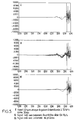
- the original signal of a guitar attack sampled at 32 kHz over a duration of 32 msec is represented respectively in I.
- the amplitude axis is graduated in relative amplitude value which makes it possible to note, at the level of the samples immediately prior to the transition proper, a large variation in amplitude compared to the samples of the same block at the start of it. .
- the coded signal is shown without processing of the pre-echoes, the coding being carried out by means of a TCDM transform and the transmission being carried out with a bit rate of 64 kbits / s.
- the phenomenon of pre-echoes is very apparent, insofar as the pre-echo noise, on the same samples immediately prior to the transition itself, presents a substantially peak-to-peak amplitude 4 to 5 times greater than the amplitude of the noise level of the samples present at the start of the corresponding block.
- the reduction in the level of the pre-echoes is particularly effective for any type of signal.
- the resulting improvement in quality is particularly noticeable especially when the coder uses a TCDM transform without there being a significant increase in the delay of the coding system. It will in fact be understood that the processing, both at the level of the coding and at the level of the decoding, is carried out in real time the transmission of the denoised samples being thus carried out in real time with the time of transmission and processing of a block close.
Landscapes
- Physics & Mathematics (AREA)
- Engineering & Computer Science (AREA)
- Probability & Statistics with Applications (AREA)
- Computer Hardware Design (AREA)
- Mathematical Physics (AREA)
- Computer Networks & Wireless Communication (AREA)
- Signal Processing (AREA)
- Compression, Expansion, Code Conversion, And Decoders (AREA)
- Digital Transmission Methods That Use Modulated Carrier Waves (AREA)
- Transmission Systems Not Characterized By The Medium Used For Transmission (AREA)
- Reduction Or Emphasis Of Bandwidth Of Signals (AREA)
Claims (9)
- Verfahren zur Verarbeitung von Vorechos eines durch Frequenztransformierte kodierten, digitalen Audiosignals, bei welchem, nach Kodierung des Signals durch Frequenztransformierte zu Koeffizienten y(k) auf Gewichtungsfenstern, welche auf N aufeinanderfolgende Abtastwerte umfassenden Blöcken von Abtastwerten x(n) gebildet sind, bei Dekodierung der Koeffizienten y(k) der Transformierten eine Filterung derart durchgeführt wird, daß bei Anwesenheit eines Übergangs der Amplitude des Signals das bei der Kodierung der Quantifizierung der Koeffizienten der Transformierten resultierende zusätzliche Rauschen verringert wird, dadurch gekennzeichnet, daß die Filterung eine optimale Filterung vom KALMAN-Filterungstyp ist.
- Verfahren nach Anspruch 1, dadurch gekennzeichnet, daß der KALMAN-Filterungsvorgang ausgehend von einer Zustandsgleichung definiert ist, welche in regressiver Form der Ordnung 2 in der Form:


bei dem Kodierungsvorgang,
- die Bestimmung einerseits der Energie σ²x(n) des Abtastwerts x(n) des Ursprungssignals und andererseits der Anwesenheit eines Übergangs auf Ebene wenigstens eines Abtastwerts x(N-q) vom Rang N-q eines bestimmten, laufenden Blocks, dann die Übertragung auf Dekodierungsebene des Werts der Parameter der Energie σ²x(n) und der Anwesenheit des Übergangs und dann
bei dem Dekodierungsvorgang- die Abschätzung der Filterungsparameter, Voraussagekoeffizienten a1, a2 der Filterung aus den Abtastwerten des vorhergehenden Blocks,- die Auswertung der Energien σ²b(n) des Kodierungsrauschens und σ²w(n) des Rauschens für den betrachteten Abtastwert vom Rang n, wodurch auf Dekodierungsebene die adaptive Filterung des verrauschten, dekodierten Signals x′(n) ermöglicht wird, um das dekodierte Signal zu rekonstruieren, in welchem die Vorechos im wesentlichen beseitigt sind. - Einrichtung zur Verarbeitung von Vorechos eines durch Frequenztransformierte kodierten digitalen Audiosignals, diese Einrichtung umfassend einerseits kaskadenartig angeordnet auf Ebene des Kodierers (1) ein Modul (10) zum Lesen von Abtastwerten x(n) des digitalen Audiosignals, welches diese letzteren in Blöcke von N Abtastwerten bringt, ein Modul (11) zur Berechnung der Frequenztransformierten, welches ausgehend von diesen Abtastwertblöcken die entsprechenden Koeffizienten y(k) der Transformierten liefert, und ein Modul (12) zur Kodierung durch Quantifizierung dieser Koeffizienten im Hinblick auf ihre Übertragung mit Hilfe eines digitalen Übertragungskanals und andererseits kaskadenartig auf Ebene des Dekodierers (2) angeordnet, den Übertragungskanal empfangend, ein Modul (20) zur Dekodierung der Koeffizienten y(k) und ein Modul (21) zur Berechnung der inversen Frequenztransformierten, wobei diese Module den Dekodierer bilden und ein dekodiertes, verrauschtes Signal x′(n) liefern, dadurch gekennzeichnet, daß die Einrichtung ferner einerseits auf Ebene des Kodierers (1) umfaßt- ein Modul (13) zur Erfassung der Übergänge, welche durch den Rang N-q des Übergangs in dem betrachteten, laufenden Block gekennzeichnet sind,- ein Modul (14) zur Extraktion der Parameter der Energie σ²x(n) des Abtastwerts x(n) oder einer Gruppe aufeinanderfolgender Abtastwerte des Ursprungssignals aus den Abtastwerten x(n),- ein Modul (15) zur Kodierung ausgehend von den Parametern der Energie σ²x(n) des Abtastwerts x(n) oder der Gruppe von Abtastwerten des Abtastwerteblocks, welches die kodierte Übertragung der Parameter der Energie σ²x(n) und eines die Anwesenheit eines Übergangs in dem betrachteten Abtastwerteblock anzeigenden Signals ermöglicht, und andererseitsauf Ebene des Dekodierers (2)- ein Modul (22) zur Rekonstruktion der übertragenen Parameter der Energie σ²x(n),- ein Modul (23) zur Extraktion der Parameter a1, a2 der Filterung aus den Abtastwerten x(n) des vorhergehenden Blocks und zur Auswertung der Energien des Innovationsrauschens σ²w(n) und des Kodierungsrauschens σ²b(n) für den betrachteten Abtastwert vom Rang n,- ein Modul (24) zur KALMAN-Filterung, welches am Filterungseingang das verrauschte, dekodierte Signal x′(n) und am Steuereingang die Parameter der Filterung a1, a2 und der Auswertung der Energien des Kodierungsrauschens σ²b(n) und des Innovationsrauschens σ²w(n) empfängt, wobei das Filterungsmodul (24) am Ausgang das gefilterte, dekodierte Signal xr(n) liefert.
- Einrichtung nach Anspruch 3, dadurch gekennzeichnet, daß sie ferner einen Zwei-Wege-Umschalter (25) umfaßt, von dem ein erster Schaltweg das gefilterte, dekodierte Signal xr(n) empfängt und von dem ein zweiter Schaltweg das von dem Modul (21) zur inversen Transformation gelieferte, dekodierte, verrauschte Signal x′(n) empfängt, wobei der Umschaltsteuerungsweg von dem die Anwesenheit eines Übergangs in dem betrachteten Abtastwerteblock anzeigende Signal (t) gesteuert ist.
- Einrichtung nach Anspruch 3 oder 4, dadurch gekennzeichnet, daß das Modul (14) zur Extraktion der Parameter der Energie σ²x(n) der Abtastwerte x(n) des Signals umfaßt
kaskadenartig angeordnet:- ein Modul (140) zur Aufteilung jedes Blocks von N Abtastwerten in aufeinanderfolgende Unterblöcke einer festgelegten Anzahl von Abtastwerten,- ein Modul (141) zur Berechnung der Energie σ²x(j) eines Abtastwerts oder einer Gruppe von Abtastwerten des Ursprungssignals. - Einrichtung nach einem der Ansprüche 3 bis 5, dadurch gekennzeichnet, daß das Kodierungsmodul umfaßt:- einen einheitlichen Quantifizierer (151), welcher ausgehend von den Parameterwerten Kodeworte liefert,- eine Schaltung (152) zur Huffmann-Kodierung.
- Einrichtung nach einem der Ansprüche 3 bis 6, dadurch gekennzeichnet, daß das Modul (23) zur Extraktion der Parameter der Filterung a1, a2 und der Auswertung der Energien des Kodierungsrauschens σ²b(n) und des Rauschens σ²w(n) parallel zu einem Eingangsanschluß der Abtastwerte x′(n) des verrauschten, dekodierten Signals umfaßt- einen ersten Weg (A) zur Berechnung der Parameter der Filterung a1, a2 und der Varianz des Innovationsrauschens σ²w(n) für den betrachteten Abtastwert vom Rang n,- einen zweiten Weg (B) zur Berechnung der Energie des Kodierungsrauschens σ²b(n), wobei die Parameter der Filterung a1, a2, des Innovationsrauschens σ²w(n) und des Kodierungsrauschens σ²b(n) dem KALMAN-Filterungsmodul zugeführt werden.
- Einrichtung nach Anspruch 7, dadurch gekennzeichnet, daß der erste Weg (A) kaskadenartig verbunden aufeinanderfolgend umfaßt:- einen Abtastwertspeicher (230), welcher die von dem Modul (21) zur inversen Transformation gelieferten, verrauschten Abtastwerte x′(n) empfängt,- eine Schaltung (231) zur Berechnung der Koeffizienten der Voraussage (ai, a1, a2) und des Verstärkungsgrads der Voraussage Gp,- eine Schaltung (232) zur Berechnung der Varianz des Innovationsrauschens σ²w(n) des Abtastwerts, wobei diese Schaltung einerseits den rekonstruierten Wert des Parameters der Energie σ²x′(n) des übertragenen Abtastwerts empfängt, welcher von dem entsprechenden Modul (22) geliefert ist, und andererseits den Voraussageverstärkungsgrad Gp, wobei das Rauschen des Abtastwerts die Beziehung:

- Einrichtung nach Anspruch 7, dadurch gekennzeichnet, daß der zweite Weg (B) kaskadenartig verbunden aufeinanderfolgend umfaßt:- eine Schaltung (233) zur Berechnung des Parameters der Energie σ²x′(n) des verrauschten Abtastwerts x′(n), wobei dieser Energieparameter eine rekursive Beziehung der Form:
 - eine Schaltung (235) zur Berechnung des Parameters des Kodierungsrauschens σ²b(n) der Abtastwerte, wobei dieser Rauschparameter eine Beziehung der Form:
Applications Claiming Priority (2)
| Application Number | Priority Date | Filing Date | Title |
|---|---|---|---|
| FR9103715 | 1991-03-27 | ||
| FR9103715A FR2674710B1 (fr) | 1991-03-27 | 1991-03-27 | Procede et systeme de traitement des preechos d'un signal audio-numerique code par transformee frequentielle. |
Publications (2)
| Publication Number | Publication Date |
|---|---|
| EP0506535A1 EP0506535A1 (de) | 1992-09-30 |
| EP0506535B1 true EP0506535B1 (de) | 1995-11-29 |
Family
ID=9411189
Family Applications (1)
| Application Number | Title | Priority Date | Filing Date |
|---|---|---|---|
| EP92400775A Expired - Lifetime EP0506535B1 (de) | 1991-03-27 | 1992-03-23 | Verfahren und Einrichtung zur Bearbeitung von Vorechos eines mittels einer Frequenztransformation kodierten digitalen Audiosignals |
Country Status (7)
| Country | Link |
|---|---|
| US (1) | US5311549A (de) |
| EP (1) | EP0506535B1 (de) |
| JP (1) | JPH0590974A (de) |
| CA (1) | CA2063954A1 (de) |
| DE (1) | DE69206300T2 (de) |
| ES (1) | ES2081583T3 (de) |
| FR (1) | FR2674710B1 (de) |
Cited By (1)
| Publication number | Priority date | Publication date | Assignee | Title |
|---|---|---|---|---|
| CN101527139B (zh) * | 2009-02-16 | 2012-03-28 | 成都九洲电子信息系统股份有限公司 | 一种音频编码解码方法及其装置 |
Families Citing this family (15)
| Publication number | Priority date | Publication date | Assignee | Title |
|---|---|---|---|---|
| FR2687871B1 (fr) * | 1992-02-25 | 1995-07-07 | France Telecom | Procede et dispositif de filtrage pour la reduction des preechos d'un signal audio-numerique. |
| JPH06112909A (ja) * | 1992-09-28 | 1994-04-22 | Sony Corp | 改良dctの信号変換装置 |
| JP3277682B2 (ja) * | 1994-04-22 | 2002-04-22 | ソニー株式会社 | 情報符号化方法及び装置、情報復号化方法及び装置、並びに情報記録媒体及び情報伝送方法 |
| US5801652A (en) * | 1994-07-08 | 1998-09-01 | Cirrus Logic, Inc. | Pattern dependent noise reduction in a digital processing circuit utilizing image circuitry |
| US5719572A (en) * | 1994-07-08 | 1998-02-17 | Cirrus Logic, Inc. | Digital signal processor with reduced pattern dependent noise |
| GB2327577B (en) | 1997-07-18 | 2002-09-11 | British Broadcasting Corp | Re-encoding decoded signals |
| FR2802041A1 (fr) * | 1999-12-07 | 2001-06-08 | Koninkl Philips Electronics Nv | Methode de detection de blocs pour canal soumis a evanouissement |
| US7711123B2 (en) * | 2001-04-13 | 2010-05-04 | Dolby Laboratories Licensing Corporation | Segmenting audio signals into auditory events |
| WO2002093560A1 (en) * | 2001-05-10 | 2002-11-21 | Dolby Laboratories Licensing Corporation | Improving transient performance of low bit rate audio coding systems by reducing pre-noise |
| US8171303B2 (en) * | 2004-11-03 | 2012-05-01 | Astav, Inc. | Authenticating a login |
| US20110057818A1 (en) * | 2006-01-18 | 2011-03-10 | Lg Electronics, Inc. | Apparatus and Method for Encoding and Decoding Signal |
| US8676365B2 (en) * | 2008-09-17 | 2014-03-18 | Orange | Pre-echo attenuation in a digital audio signal |
| KR101546849B1 (ko) | 2009-01-05 | 2015-08-24 | 삼성전자주식회사 | 주파수 영역에서의 음장효과 생성 방법 및 장치 |
| EP2772909B1 (de) * | 2011-10-27 | 2018-02-21 | LG Electronics Inc. | Verfahren zur kodierung eines sprachsignals |
| FR2992766A1 (fr) * | 2012-06-29 | 2014-01-03 | France Telecom | Attenuation efficace de pre-echos dans un signal audionumerique |
Family Cites Families (2)
| Publication number | Priority date | Publication date | Assignee | Title |
|---|---|---|---|---|
| DE3806416A1 (de) * | 1988-02-29 | 1989-09-07 | Fraunhofer Ges Forschung | Verfahren zur reduzierung sog. vorechos bei der uebertragung und/oder speicherung von akustischen signalen |
| US5079621A (en) * | 1990-06-29 | 1992-01-07 | Eastman Kodak Company | Dct transform compression, transmission and recovery of digital color using virtual filtering mechanism |
-
1991
- 1991-03-27 FR FR9103715A patent/FR2674710B1/fr not_active Expired - Fee Related
-
1992
- 1992-03-23 ES ES92400775T patent/ES2081583T3/es not_active Expired - Lifetime
- 1992-03-23 US US07/855,535 patent/US5311549A/en not_active Expired - Lifetime
- 1992-03-23 EP EP92400775A patent/EP0506535B1/de not_active Expired - Lifetime
- 1992-03-23 DE DE69206300T patent/DE69206300T2/de not_active Expired - Fee Related
- 1992-03-25 CA CA002063954A patent/CA2063954A1/en not_active Abandoned
- 1992-03-27 JP JP4071461A patent/JPH0590974A/ja not_active Withdrawn
Cited By (1)
| Publication number | Priority date | Publication date | Assignee | Title |
|---|---|---|---|---|
| CN101527139B (zh) * | 2009-02-16 | 2012-03-28 | 成都九洲电子信息系统股份有限公司 | 一种音频编码解码方法及其装置 |
Also Published As
| Publication number | Publication date |
|---|---|
| DE69206300D1 (de) | 1996-01-11 |
| DE69206300T2 (de) | 1996-04-18 |
| CA2063954A1 (en) | 1992-09-28 |
| JPH0590974A (ja) | 1993-04-09 |
| US5311549A (en) | 1994-05-10 |
| EP0506535A1 (de) | 1992-09-30 |
| FR2674710B1 (fr) | 1994-11-04 |
| ES2081583T3 (es) | 1996-03-16 |
| FR2674710A1 (fr) | 1992-10-02 |
Similar Documents
| Publication | Publication Date | Title |
|---|---|---|
| EP2002428B1 (de) | Verfahren zur trainierten diskrimination und dämpfung von echos eines digitalsignals in einem decoder und entsprechende einrichtung | |
| EP0506535A1 (de) | Verfahren und Einrichtung zur Bearbeitung von Vorechos eines mittels einer Frequenztransformation kodierten digitalen Audiosignals | |
| EP2586133B1 (de) | Steuerung einer rauschformungs-feedbackschleife in einem digitalen audiosignal-encoder | |
| FR2754127A1 (fr) | Procede de codage/decodage de signal video sur la base d'une quantification de treillis adaptative | |
| EP0906613B1 (de) | Verfahren und vorrichtung zur kodierung eines audiosignals mittels "vorwärts"- und "rückwärts"-lpc-analyse | |
| EP2176861A1 (de) | Hierarchische kodierung digitaler audiosignale | |
| EP3192073B1 (de) | Unterscheidung und dämpfung von vorechos in einem digitalen audiosignal | |
| EP1267325A1 (de) | Verfahren zur Sprachaktivitätsdetektion in einem Signal, und Sprachkodierer mit Vorrichtung zur Ausführung des Verfahrens | |
| EP2347411B1 (de) | Vor-echo-dämpfung in einem digitalaudiosignal | |
| EP0334714B1 (de) | Differentieller Kodierer mit auto-adaptivem Prädiktorfilter und dazugehörigem Dekodierer | |
| EP2232489A1 (de) | Auf transformation basierende codierung/decodierung mit adaptiven fenstern | |
| EP0078195B1 (de) | Verfahren und System zur differentiellen Kodierung und Dekodierung von Daten mit Begrenzung der Fortpflanzung von Übertragungsfehlern | |
| EP0574288B1 (de) | Verfahren und Einrichtung zur Übertragungsfehlerverdeckung von mittels einer Frequenztransformation kodierten digitalen Audiosignalen | |
| EP0078581A1 (de) | Differentialpulscode-Modulationssystem mit adaptiver Prädiktion | |
| FR2739481A1 (fr) | Appareil et procede d'elimination du bruit | |
| FR3020732A1 (fr) | Correction de perte de trame perfectionnee avec information de voisement | |
| WO2006114494A1 (fr) | Procede d’adaptation pour une interoperabilite entre modeles de correlation a cout terme de signaux numeriques | |
| CA2108663C (fr) | Procede et dispositif de filtrage pour la reduction des preechos d'un signal audio-numerique | |
| FR3133265A1 (fr) | Codage et décodage optimisé d’un signal audio utilisant un auto-encodeur à base de réseau de neurones | |
| EP0030194A1 (de) | Prediktorstufe für ein System zur Kompression des Datenflusses | |
| EP0812070B1 (de) | Verfahren und Gerät zur Kompressionskodierung eines digitalen Signals | |
| WO2009010672A2 (fr) | Limitation de distorsion introduite par un post-traitement au decodage d'un signal numerique | |
| FR2771543A1 (fr) | Procede de debruitage de signaux sonores, notamment pour le traitement de la parole | |
| FR2751776A1 (fr) | Procede d'extraction de la frequence fondamentale d'un signal de parole | |
| WO2006117453A1 (fr) | Procede d’attenuation des pre- et post-echos d’un signal numerique audio et dispositif correspondant |
Legal Events
| Date | Code | Title | Description |
|---|---|---|---|
| PUAI | Public reference made under article 153(3) epc to a published international application that has entered the european phase |
Free format text: ORIGINAL CODE: 0009012 |
|
| AK | Designated contracting states |
Kind code of ref document: A1 Designated state(s): DE ES FR GB IT NL |
|
| 17P | Request for examination filed |
Effective date: 19921006 |
|
| 17Q | First examination report despatched |
Effective date: 19940613 |
|
| GRAA | (expected) grant |
Free format text: ORIGINAL CODE: 0009210 |
|
| AK | Designated contracting states |
Kind code of ref document: B1 Designated state(s): DE ES FR GB IT NL |
|
| REF | Corresponds to: |
Ref document number: 69206300 Country of ref document: DE Date of ref document: 19960111 |
|
| GBT | Gb: translation of ep patent filed (gb section 77(6)(a)/1977) |
Effective date: 19951218 |
|
| ITF | It: translation for a ep patent filed | ||
| REG | Reference to a national code |
Ref country code: ES Ref legal event code: FG2A Ref document number: 2081583 Country of ref document: ES Kind code of ref document: T3 |
|
| PLBE | No opposition filed within time limit |
Free format text: ORIGINAL CODE: 0009261 |
|
| STAA | Information on the status of an ep patent application or granted ep patent |
Free format text: STATUS: NO OPPOSITION FILED WITHIN TIME LIMIT |
|
| 26N | No opposition filed | ||
| REG | Reference to a national code |
Ref country code: GB Ref legal event code: IF02 |
|
| PGFP | Annual fee paid to national office [announced via postgrant information from national office to epo] |
Ref country code: ES Payment date: 20090305 Year of fee payment: 18 |
|
| PGFP | Annual fee paid to national office [announced via postgrant information from national office to epo] |
Ref country code: NL Payment date: 20090223 Year of fee payment: 18 |
|
| PGFP | Annual fee paid to national office [announced via postgrant information from national office to epo] |
Ref country code: GB Payment date: 20090225 Year of fee payment: 18 |
|
| PGFP | Annual fee paid to national office [announced via postgrant information from national office to epo] |
Ref country code: IT Payment date: 20090316 Year of fee payment: 18 Ref country code: FR Payment date: 20090327 Year of fee payment: 18 Ref country code: DE Payment date: 20090327 Year of fee payment: 18 |
|
| REG | Reference to a national code |
Ref country code: NL Ref legal event code: V1 Effective date: 20101001 |
|
| GBPC | Gb: european patent ceased through non-payment of renewal fee |
Effective date: 20100323 |
|
| REG | Reference to a national code |
Ref country code: FR Ref legal event code: ST Effective date: 20101130 |
|
| PG25 | Lapsed in a contracting state [announced via postgrant information from national office to epo] |
Ref country code: NL Free format text: LAPSE BECAUSE OF NON-PAYMENT OF DUE FEES Effective date: 20101001 Ref country code: FR Free format text: LAPSE BECAUSE OF NON-PAYMENT OF DUE FEES Effective date: 20100331 |
|
| PG25 | Lapsed in a contracting state [announced via postgrant information from national office to epo] |
Ref country code: DE Free format text: LAPSE BECAUSE OF NON-PAYMENT OF DUE FEES Effective date: 20101001 |
|
| PG25 | Lapsed in a contracting state [announced via postgrant information from national office to epo] |
Ref country code: GB Free format text: LAPSE BECAUSE OF NON-PAYMENT OF DUE FEES Effective date: 20100323 Ref country code: IT Free format text: LAPSE BECAUSE OF NON-PAYMENT OF DUE FEES Effective date: 20100323 |
|
| REG | Reference to a national code |
Ref country code: ES Ref legal event code: FD2A Effective date: 20110418 |
|
| PG25 | Lapsed in a contracting state [announced via postgrant information from national office to epo] |
Ref country code: ES Free format text: LAPSE BECAUSE OF NON-PAYMENT OF DUE FEES Effective date: 20110404 |
|
| PG25 | Lapsed in a contracting state [announced via postgrant information from national office to epo] |
Ref country code: ES Free format text: LAPSE BECAUSE OF NON-PAYMENT OF DUE FEES Effective date: 20100324 |