EP0506524A1 - Auf einer Illuminationsfassung montierbares Zierelement - Google Patents
Auf einer Illuminationsfassung montierbares Zierelement Download PDFInfo
- Publication number
- EP0506524A1 EP0506524A1 EP92400739A EP92400739A EP0506524A1 EP 0506524 A1 EP0506524 A1 EP 0506524A1 EP 92400739 A EP92400739 A EP 92400739A EP 92400739 A EP92400739 A EP 92400739A EP 0506524 A1 EP0506524 A1 EP 0506524A1
- Authority
- EP
- European Patent Office
- Prior art keywords
- sleeve
- decorative element
- socket
- skirt
- decoration
- Prior art date
- Legal status (The legal status is an assumption and is not a legal conclusion. Google has not performed a legal analysis and makes no representation as to the accuracy of the status listed.)
- Withdrawn
Links
- 238000005034 decoration Methods 0.000 claims abstract description 48
- 210000005069 ears Anatomy 0.000 claims description 12
- 238000005286 illumination Methods 0.000 claims description 12
- 210000000078 claw Anatomy 0.000 claims description 8
- 230000000295 complement effect Effects 0.000 claims description 2
- 230000005489 elastic deformation Effects 0.000 claims description 2
- 239000000463 material Substances 0.000 description 9
- 239000011120 plywood Substances 0.000 description 6
- 239000003086 colorant Substances 0.000 description 5
- XEEYBQQBJWHFJM-UHFFFAOYSA-N Iron Chemical compound [Fe] XEEYBQQBJWHFJM-UHFFFAOYSA-N 0.000 description 2
- 238000004026 adhesive bonding Methods 0.000 description 2
- 239000004020 conductor Substances 0.000 description 2
- 238000004519 manufacturing process Methods 0.000 description 2
- 230000004048 modification Effects 0.000 description 2
- 238000012986 modification Methods 0.000 description 2
- 238000000465 moulding Methods 0.000 description 2
- 238000003466 welding Methods 0.000 description 2
- 241000218642 Abies Species 0.000 description 1
- 229920002160 Celluloid Polymers 0.000 description 1
- 235000008694 Humulus lupulus Nutrition 0.000 description 1
- 235000003332 Ilex aquifolium Nutrition 0.000 description 1
- 235000002296 Ilex sandwicensis Nutrition 0.000 description 1
- 235000002294 Ilex volkensiana Nutrition 0.000 description 1
- 229910052782 aluminium Inorganic materials 0.000 description 1
- XAGFODPZIPBFFR-UHFFFAOYSA-N aluminium Chemical compound [Al] XAGFODPZIPBFFR-UHFFFAOYSA-N 0.000 description 1
- 239000003708 ampul Substances 0.000 description 1
- 230000000712 assembly Effects 0.000 description 1
- 238000000429 assembly Methods 0.000 description 1
- 239000013078 crystal Substances 0.000 description 1
- 230000000694 effects Effects 0.000 description 1
- 239000011521 glass Substances 0.000 description 1
- 125000001475 halogen functional group Chemical group 0.000 description 1
- 229910052742 iron Inorganic materials 0.000 description 1
- 229910052751 metal Inorganic materials 0.000 description 1
- 239000002184 metal Substances 0.000 description 1
- 230000000717 retained effect Effects 0.000 description 1
- 230000002441 reversible effect Effects 0.000 description 1
- 230000002123 temporal effect Effects 0.000 description 1
Images

Classifications
-
- F—MECHANICAL ENGINEERING; LIGHTING; HEATING; WEAPONS; BLASTING
- F21—LIGHTING
- F21S—NON-PORTABLE LIGHTING DEVICES; SYSTEMS THEREOF; VEHICLE LIGHTING DEVICES SPECIALLY ADAPTED FOR VEHICLE EXTERIORS
- F21S4/00—Lighting devices or systems using a string or strip of light sources
- F21S4/10—Lighting devices or systems using a string or strip of light sources with light sources attached to loose electric cables, e.g. Christmas tree lights
Definitions
- the present invention relates to a decorative element adaptable to an illumination socket comprising a cylindrical skirt, which is intended to receive and hold an electric bulb, and a base which is integral with the skirt, contains the electrical connections for the bulb and can be fixed on a support frame common to several lighting sockets, said decorative element comprising an annular part which can be mounted coaxially on the socket and a decoration, of planar or approximately planar shape, which is integral with the annular part, of which the axis is in or practically in the plane of the decoration (see patent US-A-2,301,768).
- illuminations which can be arranged for example in street crossings, on street lighting candelabras, in building facades , etc.
- the illuminations can be formed by flexible strips or electric garlands, comprising one, two, three, four, five, six or even ten sockets per meter of flexible strip or garland, each socket receiving an electric bulb.
- the light bulbs are supplied with current either permanently or intermittently according to various temporal and / or spatial combinations, using special combiners.
- These flexible bands are often accompanied by patterns representing stars, fir trees, Santa Claus, or any other geometric patterns or not, formed by wooden frames, in painted or galvanized iron or more often in aluminum, on which are fixed the sockets which receive the electric light bulbs.
- the two kinds of illumination mentioned above have nothing in common with each other.
- the designs are not specially made for the lamps, while in the first case the frames of the decorative patterns are specially designed and made to receive sockets and electric bulbs which form the desired design.
- the sockets are arranged in profile so that the electric bulbs they support are decorative both on the front side and on the back side of the decorative pattern that they form.
- the decoration is usually done only on the front side and most of the time the sockets are fixed to the plywood plate so that their axis is perpendicular to the plane of said plate. If decorations are painted on both sides of the plywood plate, sockets and light bulbs must also be provided on both sides of the plywood plate. It should also be noted that the plywood lights must be strongly supported, because they have a lot of wind resistance.
- the present invention provides another solution to this problem, in the case where several lighting sockets, each equipped with its decorative element, are mounted. and aligned on a common support frame.
- the present invention also aims to provide a decorative element, which is not a general decoration, but a decoration specially adapted to each socket and to the associated electric bulb, in order to carry out a decoration for the Day as for the night extremely pleasant and forming a design married to each light bulb.
- the invention also aims to provide a decorative element which can be adapted very easily and very quickly to an illumination socket.
- the invention also aims to provide a decorative element whose manufacture is relatively inexpensive, therefore which can be made of molded material of different colors and / or shapes, so that the user can easily modify decorations in exchanging the decorative elements according to the invention, to change colors and / or shapes according to his taste and according to the events of the year to be embellished with such illuminated decorations.
- the invention also aims to provide a decorative element with which the electric bulb which is mounted in the socket is easily interchangeable, preferably without having to detach and remove the decorative element from the socket which supports it.
- the invention also. intended to provide a decorative element which, by limited dimensions and possibly by suitable positioning, has a low wind resistance.
- Another object of the invention is to provide a decorative element which can, if desired, have very bright colors, in order to present a very attractive appearance of day, that is, even when the light bulbs are off.
- the annular part of the decorative element consists of a cylindrical sleeve which can be engaged axially on the skirt of the socket and which is provided with fixing means allowing its fixing to the socket with an angular orientation determined in such a way that, when the armature carries a series of lighting sockets at intervals along its axis longitudinal, each socket being provided with a decorative element, the bulb of any one of the sockets illuminates the decorations associated with the two adjacent sockets situated on either side of the socket considered.
- Figure 1 is an elevational view showing a decorative element according to the present invention, which is adapted on a standard socket equipped with an electric bulb, as well as part of a frame on which the socket is fixed.
- FIG. 2 is a side view, along arrow F in FIG. 1.
- FIG. 3 is a sectional view along line III-III of FIG. 2, only the decorative element being represented in FIG. 3.
- FIG. 4 is a sectional view along line IV-IV of FIG. 3.
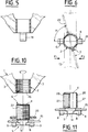
- FIG. 5 is a sectional view along the line VV in FIG. 2, only the decorative element being represented in FIG. 5.
- Figure 6 is a view similar to Figure 3 showing a variant.
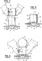
- FIG. 7 is a view partly in section and partly in elevation showing another embodiment of the decorative element of the present invention, in a position ready to be assembled with a standardized illumination socket.
- Figure 8 shows the decorative element of Figure 7 assembled with the lighting socket, the latter being further equipped with an electric bulb.
- FIG. 9 shows partly in elevation and partly in section a variant of the embodiment of FIGS. 7 and 8.
- FIG. 10 shows, partly in elevation and partly in section, yet another embodiment of the decorative element of the present invention, in a position ready to be assembled with an Illumination socket.
- FIG. 11 shows, partly in elevation and partly in section, a variant of the embodiment shown in FIG. 10.
- the decorative element 1, represented in FIGS. 1 to 5 essentially comprises a cylindrical sleeve 2 and a decoration 3 which is integral with the sleeve 2.
- the sleeve 2 and the decoration 3 can for example be made in one piece by molding d '' a plastic material capable of withstanding variations in ambient temperature and ultraviolet light.
- the sleeve 2 and the decoration 3 could also be produced separately, in a plastic material or in any other suitable material, and assembled to one another, for example by gluing or by welding.
- the sleeve 2 has an internal diameter such that it can be engaged axially, without play or with a slight radial play, on the skirt 4 of a standardized socket of illumination 5, and it is provided with fixing means 6 allowing its fixing on the socket 5.
- the socket 5 is a socket of known type and therefore does not form part of the invention. It may be a standard socket for lighting reasons, such as that which is marketed by the applicant, or even an lighting socket such as the model 60015 marketed by the LEGRAND Company.
- the socket 5 also comprises a base 8 which comprises a first pair of ears 9 located in diametrically opposite positions and pierced with holes 11 for fixing screws 12 allowing the attachment of the socket 5 on a support frame 13.
- the frame 13, which is partially shown in Figures 1 and 2 and which usually supports several sockets such as the socket 5, may for example be constituted by a metal bar .
- the base 8 of the socket 5 comprises a second pair of ears 14, which are in positions at right angles to the two ears 9. Each of the two ears 14 is crossed by one of the two electrical conductors 15 which are provided for the current supply of the bulb 7 and of the other bulbs (not shown) which equip the other sockets (not shown) fixed on the frame 13. Finally, the base 8 contains in a known manner, all the elements of connection and contact electrically connecting the two conductors 15 to the terminals of the bulb 7.
- the decoration 3 has a planar or substantially planar shape and it is preferably arranged relative to the sleeve 2 so that the plane of the decoration 3 contains the axis 16 of the sleeve 2.
- the decoration 3 extends the sleeve 2 at one end of it and extends in the manner of an arch, the feet of which are connected to the sleeve in two places 17a and 17b which are diametrically opposite the periphery of said sleeve.
- an interval d is measured, measured in the axial direction of the sleeve, which is sufficient to allow, when the decorative element 1 is adapted to the socket 5 fitted with the electric bulb 7, the removal of the said bulb and its possible replacement with another bulb without having to detach and remove the decorative element 1 from the socket 5. It can thus be formed in the decor 3 a large opening 18 which not only facilitates the fitting of the bulb 7 and its possible replacement by another bulb, but also makes it possible to significantly reduce the wind resistance of the decoration 3.
- the decoration 3, which is only partially shown in FIG. 1, can for example have the shape of a holly leaf as shown in FIG. 1, or any other desired shape, such as for example the shape of a flame or the shape of snow crystals. It can be made in any color and, preferably, in bright and vibrant colors since it does not need to be made in a transparent or translucent material.
- the fixing means 6 are constituted by two claws 19, which are integral with the sleeve 2, at its end furthest from the decoration 3, being formed for example by molding of 'one piece with the sleeve 2 as shown in particular in Figure 4.
- the two claws 19 are shaped to fit by elastic snap respectively on the two ears 14 of the base 8 as this is more particularly visible in Figure 2.
- the length of the claws 19 is chosen so as to be substantially equal to the thickness of the ears 14, so that, once they have been snapped resiliently on the ears 14, the sleeve 2 is immobilized axially, in both directions, relative to the bushing 5.
- the internal faces of the two claws 19 are plane, like the external faces of the ears 14, the sleeve 2 cannot rotate around the axis of the socket 5 after the claws 19 have been snapped onto the ears 14.
- the two claws 19 are in diametrically opposite positions at the periphery of the sleeve 2, in an axial plane 21 which makes a predetermined angle with the plane 22 in which the decoration 3 is located.
- this angle is equal to 90 °, so that the decoration 3 is aligned with the ears 9 of the base 8 and with the longitudinal axis of the bar 13 forming the support frame on which the socket 5 is fixed.
- the decor 3 is neither illuminated by the bulb 7 of the socket 5, nor by the bulbs installed in the adjacent sockets carried by the frame 13. This is why, the invention is not limited to an angle of 90 °, but, as shown in FIG.
- the planes 21 and 22 can form an angle between them ⁇ of for example 75 °.
- the plane of the decoration 3 is arranged obliquely with respect to the longitudinal axis of the frame 13 and, when the latter supports several sockets arranged at intervals along its longitudinal axis, each bulb 7 of each socket 5 illuminates its own decor 3 relatively little, but above all contributes to illuminating the decorations associated with the two adjacent sockets situated on either side of the socket considered, and vice versa. This is particularly advantageous in the case where the socket 5 and the associated bulb 7 are arranged in profile relative to the decoration 3 as is the case with the decorative element of the present invention, because it is thus possible to improve the illumination of an individual decoration 3.
- the angle ⁇ the more the decoration 3 is brightly lit by the bulbs of the neighboring sockets and the less it offers cross wind resistance, that is to say to a wind directed perpendicular to the longitudinal axis of the frame 13.
- the decoration 3 must be able to be observed in the direction of arrow F1 and / or in the direction of arrow F2
- the more the angle ⁇ is small the smaller the apparent surface of the decoration.
- the value retained for the angle ⁇ may therefore result from a compromise between obtaining good lighting of the decor and a low wind resistance, on the one hand, and obtaining a large apparent surface. scenery 3, on the other hand.
- the frame 13 is curved in the shape of a circle or of a polygon, the decorations 3 inclined at an angle ⁇ then form blades like those of a wind turbine. It follows that if the frame 13, of circular or polygonal shape, is rotatably mounted around an axis passing through its center, it is then possible to produce an Illuminated decorative assembly, which can be animated by a movement of rotation under the effect of the wind, thus giving this decorative set a particularly attractive character.
- FIGS. 7 and 8 which show another embodiment of the present invention, the elements which are identical or which play the same role as those of FIGS. 1 to 5 are designated by the same reference numbers and will not be therefore not described again in detail.
- the embodiment of Figures 7 and 8 differs essentially from that of Figures 1 to 5 by the fact that the fixing means 6 here consist of at least one projection 23 and a recess 24 which can. be engaged with each other by elastic deformation of the sleeve 2 of the decorative element 1 when the latter is engaged axially on the skirt 4 of the sleeve 5.
- the projection 23 can for example be formed on the outer cylindrical surface of the skirt 4 of the sleeve 5, the recess 24 then being formed in the inner cylindrical surface of the sleeve 2.
- the projection 23 could be formed on the inner cylindrical surface of the sleeve 2 and the recess 24 in the outer cylindrical surface of the skirt 4.
- the projection 23 and the hollow 24 are formed on the surfaces of the sleeve 2 and of the skirt 4 in positions such that, after the decorative element 1 has been placed on the sleeve 5 as shown in FIG. 8, the decoration 3 has an orientation predetermined by relative to the axis 16 of the socket 5, for example the same orientation as that shown in FIG. 3 or that that shown in FIG. 6.
- FIG. 7 Another recesses 24 can advantageously be provided, as shown in FIG. 7, which are formed in positions regularly spaced circumferentially, for example in the internal cylindrical surface of the sleeve 2.
- the projection 23 can be engaged in any of the recesses 24 to give the sleeve 2, therefore the decoration 3, an orientation chosen from among several possible predetermined orientations.
- the socket 5 must have a projection 23 (or a recess 24) which is not usually provided on the known standard sockets and which therefore requires a modification of the mold used for manufacturing. of these known sockets. It also results therefrom that the decorative element 1 of FIG. 7 cannot be fixed on existing standardized sockets already fitted to decorative assemblies. To remedy this, it is possible to provide an intermediate sleeve 25, having an inside diameter corresponding to the outside diameter of the skirt 4 of the standard socket 5, so that it can be engaged axially on the latter.
- the intermediate sleeve 25 can be fixed to the skirt 4 of the sleeve 5 for example by gluing, by welding or by any other suitable means.
- the projection 23 (or the recess (s) 24) can then be formed on the cylindrical outer surface of the intermediate sleeve 25 as shown in FIG. 9.
- the sleeve 2 of the decorative element 1 must have a inner diameter corresponding to the outer diameter of the intermediate sleeve 25.
- the projection 23 (or hollow 24) any desired angular position around the axis 16 of the sleeve. This gives the user an additional possibility of adjusting the orientation of the decoration 3.
- FIG. 10 which shows a third embodiment of the present invention
- the elements which are identical or which play the same role as those of the preceding embodiments are designated by the same reference numbers and will therefore not be described in new in detail.
- the embodiment of FIG. 10 essentially differs from the previous embodiments in that the means 6 allowing the attachment of the decorative element 1 to the bush 5 are here constituted by a first thread 26, which is formed on the cylindrical surface inside of the sleeve 2, and by a second thread 27, which is complementary to the first thread 26 and which is formed either on the surface external cylindrical of the skirt 4 of the sleeve 5 (FIG. 10), that is to say the external cylindrical surface of an intermediate sleeve 28 (FIG.
- the decorative element 1 can be adapted and fixed to the socket 5 by screwing the sleeve 2 either directly on the socket 5 ( Figure 10) or on the intermediate sleeve 28 ( Figure 11) previously installed on the standardized socket 5.
- a lock nut 29 is also provided (FIG. 10), which is also screwed onto the thread 27 of the skirt 4 (or of the intermediate sleeve 28) and which advantageously makes it possible to block the sleeve 2, therefore also the decor 3, in any desired angular position relative to the sleeve 5.
- the angle ⁇ in Figure 6 can be changed at will and continuously.
- the hollows 24 of the embodiment of FIG. 7 only allow adjustment by hops each time of an angle corresponding to the angular difference between two hollows.
- the lock nut 29 can itself have a decorative shape (openwork disc or not, saucer, star, etc.).
Landscapes
- Engineering & Computer Science (AREA)
- General Engineering & Computer Science (AREA)
- Non-Portable Lighting Devices Or Systems Thereof (AREA)
Applications Claiming Priority (2)
| Application Number | Priority Date | Filing Date | Title |
|---|---|---|---|
| FR9103837 | 1991-03-29 | ||
| FR9103837A FR2674609A1 (fr) | 1991-03-29 | 1991-03-29 | Element decoratif adaptable sur une douille d'illumination. |
Publications (1)
| Publication Number | Publication Date |
|---|---|
| EP0506524A1 true EP0506524A1 (de) | 1992-09-30 |
Family
ID=9411263
Family Applications (1)
| Application Number | Title | Priority Date | Filing Date |
|---|---|---|---|
| EP92400739A Withdrawn EP0506524A1 (de) | 1991-03-29 | 1992-03-19 | Auf einer Illuminationsfassung montierbares Zierelement |
Country Status (2)
| Country | Link |
|---|---|
| EP (1) | EP0506524A1 (de) |
| FR (1) | FR2674609A1 (de) |
Cited By (1)
| Publication number | Priority date | Publication date | Assignee | Title |
|---|---|---|---|---|
| FR2720553A1 (fr) * | 1994-05-26 | 1995-12-01 | Michel Scola | Dispositif de protection contre les contacts pour douilles d'ampoules électriques. |
Citations (4)
| Publication number | Priority date | Publication date | Assignee | Title |
|---|---|---|---|---|
| US2301768A (en) * | 1940-04-22 | 1942-11-10 | Noma Electric Corp | Illuminating device |
| US2714652A (en) * | 1952-08-18 | 1955-08-02 | Harry G P Meyer | Illuminated garden ornament assemblies |
| DE2117830A1 (de) * | 1970-01-14 | 1971-10-28 | Kaltenegger J | Reflektorhülse für Grableuchten oder dgl |
| FR2228192A1 (de) * | 1973-05-02 | 1974-11-29 | Droguet Int |
-
1991
- 1991-03-29 FR FR9103837A patent/FR2674609A1/fr active Pending
-
1992
- 1992-03-19 EP EP92400739A patent/EP0506524A1/de not_active Withdrawn
Patent Citations (4)
| Publication number | Priority date | Publication date | Assignee | Title |
|---|---|---|---|---|
| US2301768A (en) * | 1940-04-22 | 1942-11-10 | Noma Electric Corp | Illuminating device |
| US2714652A (en) * | 1952-08-18 | 1955-08-02 | Harry G P Meyer | Illuminated garden ornament assemblies |
| DE2117830A1 (de) * | 1970-01-14 | 1971-10-28 | Kaltenegger J | Reflektorhülse für Grableuchten oder dgl |
| FR2228192A1 (de) * | 1973-05-02 | 1974-11-29 | Droguet Int |
Cited By (1)
| Publication number | Priority date | Publication date | Assignee | Title |
|---|---|---|---|---|
| FR2720553A1 (fr) * | 1994-05-26 | 1995-12-01 | Michel Scola | Dispositif de protection contre les contacts pour douilles d'ampoules électriques. |
Also Published As
| Publication number | Publication date |
|---|---|
| FR2674609A1 (fr) | 1992-10-02 |
Similar Documents
| Publication | Publication Date | Title |
|---|---|---|
| FR2654594A1 (fr) | Structure de monture de bijouterie utilisant des elements de presentation rotatifs. | |
| LU87576A1 (fr) | Dispositif d'entrainement rotatif | |
| WO1997038609A1 (fr) | Structure a montage tournant pour la presentation d'elements decoratifs | |
| CA1265112A (fr) | Collet support pour abat-jour | |
| US2857507A (en) | Electric lawn ornament | |
| CA2345822A1 (en) | Spinning mobile | |
| EP0357523A1 (de) | Verzierte Vorderseite einer Brillenfassung | |
| US7399110B2 (en) | Decorative light system | |
| WO2010150069A1 (fr) | Systeme d'eclairage pour article de joaillerie a sources lumineuses mobiles | |
| EP0506524A1 (de) | Auf einer Illuminationsfassung montierbares Zierelement | |
| CH719889B1 (fr) | Pièce d'horlogerie comprenant un cadran supportant un décor | |
| WO2018083388A1 (fr) | Bijou | |
| CA2328574C (fr) | Ampoule electrique a miroir et rampe d'eclairage comportant au moins une telle ampoule | |
| LU87587A1 (fr) | Objet decoratif mobile | |
| FR2713747A1 (fr) | Dispositif lumineux de signalisation. | |
| EP1319998B1 (de) | Leuchtzeiger und diese aufweisendes Anzeigegerät, insbesondere für eine Uhr | |
| CH701348B1 (fr) | Système d'éclairage bijoux à sources lumineuses mobiles. | |
| FR3016570A1 (fr) | Dispositif d'eclairage a circuit commutable pour vehicule automobile | |
| BE1003490A7 (fr) | Mecanisme d'entrainement de store. | |
| EP0791865B1 (de) | Taschen- und Tischuhr mit einer Aufhänge- und Haltevorrichtung | |
| FR2765996A1 (fr) | Enseigne lumineuse | |
| FR2764967A3 (fr) | Dispositif de lampes en reseau selon divers agencements matriciels | |
| FR2751396A1 (fr) | Structure lumineuse a fixation d'une guirlande lumineuse | |
| FR2777988A1 (fr) | Dispositif de realisation d'un panneau decor artifice | |
| FR2468275A1 (fr) | Lampe d'endormissement pour insomniaques |
Legal Events
| Date | Code | Title | Description |
|---|---|---|---|
| PUAI | Public reference made under article 153(3) epc to a published international application that has entered the european phase |
Free format text: ORIGINAL CODE: 0009012 |
|
| AK | Designated contracting states |
Kind code of ref document: A1 Designated state(s): AT BE CH DE DK ES FR GB GR IT LI LU MC NL PT SE |
|
| 17P | Request for examination filed |
Effective date: 19920827 |
|
| 17Q | First examination report despatched |
Effective date: 19940330 |
|
| STAA | Information on the status of an ep patent application or granted ep patent |
Free format text: STATUS: THE APPLICATION IS DEEMED TO BE WITHDRAWN |
|
| 18D | Application deemed to be withdrawn |
Effective date: 19950420 |