EP0506496A1 - Aus zusammengesetzten Teilen hergestellter Käfig, insbesondere für Wälzlager mit hoher Betriebstemperatur - Google Patents
Aus zusammengesetzten Teilen hergestellter Käfig, insbesondere für Wälzlager mit hoher Betriebstemperatur Download PDFInfo
- Publication number
- EP0506496A1 EP0506496A1 EP92400310A EP92400310A EP0506496A1 EP 0506496 A1 EP0506496 A1 EP 0506496A1 EP 92400310 A EP92400310 A EP 92400310A EP 92400310 A EP92400310 A EP 92400310A EP 0506496 A1 EP0506496 A1 EP 0506496A1
- Authority
- EP
- European Patent Office
- Prior art keywords
- rolling bodies
- cage
- retaining ring
- ring
- cage according
- Prior art date
- Legal status (The legal status is an assumption and is not a legal conclusion. Google has not performed a legal analysis and makes no representation as to the accuracy of the status listed.)
- Granted
Links
- 238000005096 rolling process Methods 0.000 claims abstract description 26
- 239000000463 material Substances 0.000 claims description 6
- OKTJSMMVPCPJKN-UHFFFAOYSA-N Carbon Chemical compound [C] OKTJSMMVPCPJKN-UHFFFAOYSA-N 0.000 claims description 3
- 229910002804 graphite Inorganic materials 0.000 claims description 3
- 239000010439 graphite Substances 0.000 claims description 3
- 230000001050 lubricating effect Effects 0.000 claims description 3
- 239000000654 additive Substances 0.000 claims description 2
- 229910010293 ceramic material Inorganic materials 0.000 claims description 2
- 239000000945 filler Substances 0.000 claims description 2
- 229910001092 metal group alloy Inorganic materials 0.000 claims description 2
- 230000003647 oxidation Effects 0.000 claims description 2
- 238000007254 oxidation reaction Methods 0.000 claims description 2
- 239000011248 coating agent Substances 0.000 claims 1
- 238000000576 coating method Methods 0.000 claims 1
- 230000014759 maintenance of location Effects 0.000 abstract description 2
- PZNSFCLAULLKQX-UHFFFAOYSA-N Boron nitride Chemical compound N#B PZNSFCLAULLKQX-UHFFFAOYSA-N 0.000 description 2
- 229910052581 Si3N4 Inorganic materials 0.000 description 2
- 239000000919 ceramic Substances 0.000 description 2
- 230000002349 favourable effect Effects 0.000 description 2
- HQVNEWCFYHHQES-UHFFFAOYSA-N silicon nitride Chemical compound N12[Si]34N5[Si]62N3[Si]51N64 HQVNEWCFYHHQES-UHFFFAOYSA-N 0.000 description 2
- 229910052582 BN Inorganic materials 0.000 description 1
- VYZAMTAEIAYCRO-UHFFFAOYSA-N Chromium Chemical compound [Cr] VYZAMTAEIAYCRO-UHFFFAOYSA-N 0.000 description 1
- 238000005452 bending Methods 0.000 description 1
- 229910052804 chromium Inorganic materials 0.000 description 1
- 239000011651 chromium Substances 0.000 description 1
- 239000002131 composite material Substances 0.000 description 1
- 230000006835 compression Effects 0.000 description 1
- 238000007906 compression Methods 0.000 description 1
- 239000000470 constituent Substances 0.000 description 1
- 230000000694 effects Effects 0.000 description 1
- 238000010438 heat treatment Methods 0.000 description 1
- 238000005461 lubrication Methods 0.000 description 1
- 239000011253 protective coating Substances 0.000 description 1
Images


Classifications
-
- F—MECHANICAL ENGINEERING; LIGHTING; HEATING; WEAPONS; BLASTING
- F16—ENGINEERING ELEMENTS AND UNITS; GENERAL MEASURES FOR PRODUCING AND MAINTAINING EFFECTIVE FUNCTIONING OF MACHINES OR INSTALLATIONS; THERMAL INSULATION IN GENERAL
- F16C—SHAFTS; FLEXIBLE SHAFTS; ELEMENTS OR CRANKSHAFT MECHANISMS; ROTARY BODIES OTHER THAN GEARING ELEMENTS; BEARINGS
- F16C33/00—Parts of bearings; Special methods for making bearings or parts thereof
- F16C33/30—Parts of ball or roller bearings
- F16C33/38—Ball cages
- F16C33/44—Selection of substances
-
- F—MECHANICAL ENGINEERING; LIGHTING; HEATING; WEAPONS; BLASTING
- F16—ENGINEERING ELEMENTS AND UNITS; GENERAL MEASURES FOR PRODUCING AND MAINTAINING EFFECTIVE FUNCTIONING OF MACHINES OR INSTALLATIONS; THERMAL INSULATION IN GENERAL
- F16C—SHAFTS; FLEXIBLE SHAFTS; ELEMENTS OR CRANKSHAFT MECHANISMS; ROTARY BODIES OTHER THAN GEARING ELEMENTS; BEARINGS
- F16C33/00—Parts of bearings; Special methods for making bearings or parts thereof
- F16C33/30—Parts of ball or roller bearings
- F16C33/38—Ball cages
- F16C33/3831—Ball cages with hybrid structure, i.e. with parts made of distinct materials
-
- F—MECHANICAL ENGINEERING; LIGHTING; HEATING; WEAPONS; BLASTING
- F16—ENGINEERING ELEMENTS AND UNITS; GENERAL MEASURES FOR PRODUCING AND MAINTAINING EFFECTIVE FUNCTIONING OF MACHINES OR INSTALLATIONS; THERMAL INSULATION IN GENERAL
- F16C—SHAFTS; FLEXIBLE SHAFTS; ELEMENTS OR CRANKSHAFT MECHANISMS; ROTARY BODIES OTHER THAN GEARING ELEMENTS; BEARINGS
- F16C33/00—Parts of bearings; Special methods for making bearings or parts thereof
- F16C33/30—Parts of ball or roller bearings
- F16C33/38—Ball cages
- F16C33/3837—Massive or moulded cages having cage pockets surrounding the balls, e.g. machined window cages
- F16C33/3862—Massive or moulded cages having cage pockets surrounding the balls, e.g. machined window cages comprising two annular parts joined together
-
- F—MECHANICAL ENGINEERING; LIGHTING; HEATING; WEAPONS; BLASTING
- F16—ENGINEERING ELEMENTS AND UNITS; GENERAL MEASURES FOR PRODUCING AND MAINTAINING EFFECTIVE FUNCTIONING OF MACHINES OR INSTALLATIONS; THERMAL INSULATION IN GENERAL
- F16C—SHAFTS; FLEXIBLE SHAFTS; ELEMENTS OR CRANKSHAFT MECHANISMS; ROTARY BODIES OTHER THAN GEARING ELEMENTS; BEARINGS
- F16C43/00—Assembling bearings
- F16C43/04—Assembling rolling-contact bearings
- F16C43/06—Placing rolling bodies in cages or bearings
- F16C43/08—Placing rolling bodies in cages or bearings by deforming the cages or the races
-
- F—MECHANICAL ENGINEERING; LIGHTING; HEATING; WEAPONS; BLASTING
- F16—ENGINEERING ELEMENTS AND UNITS; GENERAL MEASURES FOR PRODUCING AND MAINTAINING EFFECTIVE FUNCTIONING OF MACHINES OR INSTALLATIONS; THERMAL INSULATION IN GENERAL
- F16C—SHAFTS; FLEXIBLE SHAFTS; ELEMENTS OR CRANKSHAFT MECHANISMS; ROTARY BODIES OTHER THAN GEARING ELEMENTS; BEARINGS
- F16C19/00—Bearings with rolling contact, for exclusively rotary movement
- F16C19/02—Bearings with rolling contact, for exclusively rotary movement with bearing balls essentially of the same size in one or more circular rows
- F16C19/04—Bearings with rolling contact, for exclusively rotary movement with bearing balls essentially of the same size in one or more circular rows for radial load mainly
- F16C19/06—Bearings with rolling contact, for exclusively rotary movement with bearing balls essentially of the same size in one or more circular rows for radial load mainly with a single row or balls
-
- F—MECHANICAL ENGINEERING; LIGHTING; HEATING; WEAPONS; BLASTING
- F16—ENGINEERING ELEMENTS AND UNITS; GENERAL MEASURES FOR PRODUCING AND MAINTAINING EFFECTIVE FUNCTIONING OF MACHINES OR INSTALLATIONS; THERMAL INSULATION IN GENERAL
- F16C—SHAFTS; FLEXIBLE SHAFTS; ELEMENTS OR CRANKSHAFT MECHANISMS; ROTARY BODIES OTHER THAN GEARING ELEMENTS; BEARINGS
- F16C2206/00—Materials with ceramics, cermets, hard carbon or similar non-metallic hard materials as main constituents
-
- F—MECHANICAL ENGINEERING; LIGHTING; HEATING; WEAPONS; BLASTING
- F16—ENGINEERING ELEMENTS AND UNITS; GENERAL MEASURES FOR PRODUCING AND MAINTAINING EFFECTIVE FUNCTIONING OF MACHINES OR INSTALLATIONS; THERMAL INSULATION IN GENERAL
- F16C—SHAFTS; FLEXIBLE SHAFTS; ELEMENTS OR CRANKSHAFT MECHANISMS; ROTARY BODIES OTHER THAN GEARING ELEMENTS; BEARINGS
- F16C2226/00—Joining parts; Fastening; Assembling or mounting parts
- F16C2226/50—Positive connections
- F16C2226/70—Positive connections with complementary interlocking parts
- F16C2226/74—Positive connections with complementary interlocking parts with snap-fit, e.g. by clips
-
- F—MECHANICAL ENGINEERING; LIGHTING; HEATING; WEAPONS; BLASTING
- F16—ENGINEERING ELEMENTS AND UNITS; GENERAL MEASURES FOR PRODUCING AND MAINTAINING EFFECTIVE FUNCTIONING OF MACHINES OR INSTALLATIONS; THERMAL INSULATION IN GENERAL
- F16C—SHAFTS; FLEXIBLE SHAFTS; ELEMENTS OR CRANKSHAFT MECHANISMS; ROTARY BODIES OTHER THAN GEARING ELEMENTS; BEARINGS
- F16C2300/00—Application independent of particular apparatuses
- F16C2300/40—Application independent of particular apparatuses related to environment, i.e. operating conditions
- F16C2300/54—Application independent of particular apparatuses related to environment, i.e. operating conditions high-temperature
Definitions
- the invention relates to a cage with assembled elements, in particular for bearings at high operating temperature, in which a first element carries separators which delimit cells for receiving the rolling bodies respectively provided with a mounting termination for a retaining ring. and axial closure of the cells.
- the publication FR-A-2630171 describes a cage in which the terminations carried by the first element are engaged by deformation in recesses distributed circumferentially on the retaining ring.
- Publication FR-A-2562615 describes a cage in which the first element deforms as a result of the force exerted by the axial contact of the terminations on the rolling bodies and facilitates the introduction of the rolling bodies before mounting the retaining ring.
- the retaining ring prevents the deformation of the cage element which ensures the retention of the rolling bodies and prevents it from being released from the rolling bodies under the effect of contact stresses during bearing operation.
- the invention therefore relates to a cage with assembled elements intended to be mounted in a bearing, in which the rolling bodies are arranged between an inner ring and an outer ring.
- the invention also relates to a cage with assembled elements, of which the first element with separators, is introduced axially between the rings of the bearing, the openings of the cells being opposite the prepositioned rolling bodies and in which the retaining ring is in support on said rolling bodies.
- the subject of the invention is a cage of assembled elements made of composite material, the first element of which is free from mounting constraints and in which the retaining ring absorbs a large part of the bending forces exerted on the separators by the rolling bodies during their passages in the bearing load area.
- the mounting terminations are axially limited by the edge of at least one recess groove of a retaining ring whose opposite edge is axially offset with respect to the bearing face of the ring on the rolling bodies.
- the cage thus produced advantageously uses a rigid element which has lubrication properties and a thin section retaining ring, the material of which allows it to absorb stresses and deformations.
- the cage according to the invention has a stress-free element which advantageously applies the lubricating and thermal resistance properties of graphite, on which the retaining ring can be mounted after heating and differential expansion of the constituent elements.
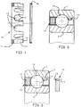
- Figure 1 is a cross section of the two components of the cage.
- FIG. 2 is a half-view in radial section of a bearing fitted with a cage as shown in FIG. 1.
- Figure 3 is a half-view in radial section of the bearing shown in Figure 1 during assembly of the retaining ring.
- Figure 4 is a half-view in partial radial section of the bearing with an alternative embodiment of the cage which has enveloping cells along the axis of the bearing.
- FIG. 5 describes an alternative embodiment of the cage, the retaining element of which has radial undulations tangent to the rolling bodies giving it a increased elasticity facilitating assembly.
- Figure 6 is a circumferential sectional view of the cage shown in Figure 4, taken along the line VI-VI of Figure 4.
- Figure 7 describes an alternative embodiment of the cage with two retaining rings.
- the cage according to the invention consists of a first element 10 formed by an annular base 11 from which extend axially separators 12 which delimit cells 13 for the rolling bodies 14 and by a ring retainer 16 which closes the cells 13.
- the separators 12 respectively carry a mounting end 15 of the retaining ring 16.
- the ring 16 will be mounted in a recess groove 17 carried by each termination 15. For this purpose, it is axially limited by an edge 17 'of the groove.
- the opposite edge 17 ⁇ of the groove is axially offset with respect to the bearing face of the ring 16 on the rolling bodies 14.
- Figure 3 shows the bearing during assembly of the cage.
- the first element 10 is previously mounted on the rolling bodies 14 disposed between the outer ring 1 and inner 2.
- the rings 1 and 2 have incidentally additional bearing surfaces ensuring the centering of the elements of the cage during operation.
- the latter In order to facilitate the mounting of the retaining ring 16, the latter carries a chamfer 18 tangent to the rolling bodies 14 and can be split to be mounted in the manner of an elastic stop ring.
- the retaining ring 16 is mounted in the groove 17 by force or by differential expansion.
- the face 19 of the ring opposite the chamfer 10 thus comes to bear on the edge 17 'of the groove.
- the rolling bodies 14 come indifferently to bear on the bottom of the cells or on the retaining ring.
- Figures 4 and 6 relate to an alternative embodiment of the cage according to which the cells 13 have edges partially enveloping the rolling bodies 14 along the axis of the bearing.
- FIG. 5 relates to an alternative embodiment of the retaining ring according to which the circumferential part carries radial undulations 20 bearing on the rolling bodies. This results in a larger contact surface, reduced contact pressures as well as an increased elasticity of the ring which facilitates the assembly of the cage 10.
- FIG. 7 shows an alternative embodiment of the cage mounted in a bearing.
- a groove such as 17 allows the embedding of the retaining ring and extends to the exterior surface 12e and interior 12i for the reception of two functionally similar retaining rings 16, 16 ′ which have chamfers 18, 18 ′ in contact with the rolling bodies 14.
- These two rings can be mounted with clamping on the cage 10 so as to compensate for the deformations that can be induced.
- the separators 12 are then only subjected to compression stresses between the two rings. This also makes it possible to compensate for any differences in expansion between the elements.
- the axial pressure constraints between the rolling bodies and the cage are in this case absorbed by all of the rings 16, 16 ′.
- the various embodiments of the cage can advantageously use retaining rings provided with a radial slot in order to give them an additional elasticity favorable to mounting on the element 10.
- the element 10 with separators is made of a graphite-based material or a ceramic material with additives or fillers such as boron nitride (NB) which give the element 10 the desired lubricating properties.
- the retaining ring 16 is made of a metal alloy particularly resistant to high temperatures.
- a protective coating against oxidation such as chromium or a ceramic deposit may be envisaged to give the ring increased resistance to wear and favorable anti-friction properties during the operation of the bearing.
Landscapes
- Engineering & Computer Science (AREA)
- General Engineering & Computer Science (AREA)
- Mechanical Engineering (AREA)
- Rolling Contact Bearings (AREA)
Applications Claiming Priority (2)
| Application Number | Priority Date | Filing Date | Title |
|---|---|---|---|
| FR9103858A FR2674584B1 (fr) | 1991-03-29 | 1991-03-29 | Cage a elements assembles, notamment pour roulements a haute temperature de fonctionnement. |
| FR9103858 | 1991-03-29 |
Publications (2)
| Publication Number | Publication Date |
|---|---|
| EP0506496A1 true EP0506496A1 (de) | 1992-09-30 |
| EP0506496B1 EP0506496B1 (de) | 1994-09-21 |
Family
ID=9411285
Family Applications (1)
| Application Number | Title | Priority Date | Filing Date |
|---|---|---|---|
| EP92400310A Expired - Lifetime EP0506496B1 (de) | 1991-03-29 | 1992-02-07 | Aus zusammengesetzten Teilen hergestellter Käfig, insbesondere für Wälzlager mit hoher Betriebstemperatur |
Country Status (4)
| Country | Link |
|---|---|
| EP (1) | EP0506496B1 (de) |
| DE (1) | DE69200426T2 (de) |
| ES (1) | ES2060453T3 (de) |
| FR (1) | FR2674584B1 (de) |
Cited By (3)
| Publication number | Priority date | Publication date | Assignee | Title |
|---|---|---|---|---|
| DE102006017091A1 (de) * | 2006-04-10 | 2007-10-11 | Fev Motorentechnik Gmbh | Lagerkäfig für ein Wälzlager zur axialen Montage und ungeteilte Kurbelwelle mit Wälzlagern |
| DE102009056035A1 (de) | 2009-11-27 | 2011-06-01 | Schaeffler Technologies Gmbh & Co. Kg | Wälzlager |
| WO2013143695A1 (de) * | 2012-03-27 | 2013-10-03 | Technische Universität Kaiserslautern | Feststoffgeschmiertes wälzlager |
Families Citing this family (2)
| Publication number | Priority date | Publication date | Assignee | Title |
|---|---|---|---|---|
| DE102018212383A1 (de) * | 2018-07-25 | 2020-01-30 | CEROBEAR GmbH | Wälzlagerkäfig |
| DE102020202864A1 (de) | 2020-03-06 | 2021-09-09 | Minebea Mitsumi Inc. | Wälzlagerkäfig und Wälzlager |
Citations (6)
| Publication number | Priority date | Publication date | Assignee | Title |
|---|---|---|---|---|
| DE282425C (de) * | ||||
| FR756333A (fr) * | 1933-05-05 | 1933-12-08 | Skf Svenska Kullagerfab Ab | Roulement à rouleaux |
| FR807508A (fr) * | 1935-10-01 | 1937-01-14 | Dispositif de retenue pour les rouleaux ou les aiguilles des roulements à rouleaux ou à aiguilles | |
| DE923583C (de) * | 1952-12-23 | 1955-02-17 | Skf Kugellagerfabriken Gmbh | Zerlegbarer Kaefig fuer grosse Rollenlager, insbesondere Walzwerks-Rollenlager |
| GB1563935A (en) * | 1976-12-24 | 1980-04-02 | Ransome Hoffmann Pollard | Cage |
| EP0304872A2 (de) * | 1987-08-26 | 1989-03-01 | Koyo Seiko Co., Ltd. | Hitzebeständiges Kugellager |
Family Cites Families (2)
| Publication number | Priority date | Publication date | Assignee | Title |
|---|---|---|---|---|
| GB2156912B (en) * | 1984-04-04 | 1987-09-03 | Skf Svenska Kullagerfab Ab | Cage for bearings |
| DE3812345C2 (de) * | 1988-04-14 | 1996-07-11 | Skf Gmbh | Zwei- oder mehrteiliger Wälzlagerkäfig |
-
1991
- 1991-03-29 FR FR9103858A patent/FR2674584B1/fr not_active Expired - Fee Related
-
1992
- 1992-02-07 EP EP92400310A patent/EP0506496B1/de not_active Expired - Lifetime
- 1992-02-07 DE DE69200426T patent/DE69200426T2/de not_active Expired - Fee Related
- 1992-02-07 ES ES92400310T patent/ES2060453T3/es not_active Expired - Lifetime
Patent Citations (6)
| Publication number | Priority date | Publication date | Assignee | Title |
|---|---|---|---|---|
| DE282425C (de) * | ||||
| FR756333A (fr) * | 1933-05-05 | 1933-12-08 | Skf Svenska Kullagerfab Ab | Roulement à rouleaux |
| FR807508A (fr) * | 1935-10-01 | 1937-01-14 | Dispositif de retenue pour les rouleaux ou les aiguilles des roulements à rouleaux ou à aiguilles | |
| DE923583C (de) * | 1952-12-23 | 1955-02-17 | Skf Kugellagerfabriken Gmbh | Zerlegbarer Kaefig fuer grosse Rollenlager, insbesondere Walzwerks-Rollenlager |
| GB1563935A (en) * | 1976-12-24 | 1980-04-02 | Ransome Hoffmann Pollard | Cage |
| EP0304872A2 (de) * | 1987-08-26 | 1989-03-01 | Koyo Seiko Co., Ltd. | Hitzebeständiges Kugellager |
Cited By (4)
| Publication number | Priority date | Publication date | Assignee | Title |
|---|---|---|---|---|
| DE102006017091A1 (de) * | 2006-04-10 | 2007-10-11 | Fev Motorentechnik Gmbh | Lagerkäfig für ein Wälzlager zur axialen Montage und ungeteilte Kurbelwelle mit Wälzlagern |
| DE102009056035A1 (de) | 2009-11-27 | 2011-06-01 | Schaeffler Technologies Gmbh & Co. Kg | Wälzlager |
| WO2011064063A1 (de) | 2009-11-27 | 2011-06-03 | Schaeffler Technologies Gmbh & Co. Kg | Wälzlager blechkammkäfig und verfahren zu dessen zusammenbau |
| WO2013143695A1 (de) * | 2012-03-27 | 2013-10-03 | Technische Universität Kaiserslautern | Feststoffgeschmiertes wälzlager |
Also Published As
| Publication number | Publication date |
|---|---|
| FR2674584B1 (fr) | 1993-05-21 |
| DE69200426T2 (de) | 1995-04-20 |
| EP0506496B1 (de) | 1994-09-21 |
| DE69200426D1 (de) | 1994-10-27 |
| ES2060453T3 (es) | 1994-11-16 |
| FR2674584A1 (fr) | 1992-10-02 |
Similar Documents
| Publication | Publication Date | Title |
|---|---|---|
| FR2759129A1 (fr) | Roulement et palier comportant un insert de compensation thermique | |
| EP1851452B1 (de) | Führungselement | |
| FR2680844A1 (fr) | Dispositif de debrayage a commande hydraulique pour embrayage a friction pour vehicule automobile. | |
| FR2640010A1 (fr) | Agencement pour la fixation d'une bague de roulement de grande durete dans la surface d'alesage de plus faible durete d'un logement ou sur la surface laterale de plus faible durete d'un arbre ou d'un organe analogue | |
| EP2110570B1 (de) | Verfahren zur Herstellung einer Rollvorrichtung | |
| FR2565645A1 (fr) | Dispositif de transmission du couple | |
| EP1707647B1 (de) | Lager mit Verstärktem Ring und Käfig mit Deflektor | |
| EP0506496B1 (de) | Aus zusammengesetzten Teilen hergestellter Käfig, insbesondere für Wälzlager mit hoher Betriebstemperatur | |
| EP1564435A1 (de) | Axiallager für ein Schwungrad | |
| FR2927679A1 (fr) | Dispositif de debrayage | |
| FR2978219A1 (fr) | Montage d’un arbre tournant dans un carter par l’intermediaire d’un roulement | |
| FR3094049A1 (fr) | Rotule sphérique | |
| FR2563875A1 (fr) | Palier de volant moteur | |
| EP2878838B1 (de) | Kegelrollenlager mit Rückhaltekäfig für Rollkörpern | |
| FR2800136A1 (fr) | Liaison entre un premier element de machine et un second element de machine, en particulier entre une bague de roulement et un logement | |
| FR2933757A1 (fr) | Ensemble de palier a roulement | |
| FR3119427A1 (fr) | Palier lisse ou à roulement équipé d’un dispositif d’étanchéité avec un siège de joint proche de l’axe de révolution | |
| FR2682438A1 (fr) | Montage de roulement comportant une bague exterieure immobilisee dans un alesage. | |
| FR2886693A1 (fr) | Dispositif anti-rotation pour bague de roulement, et roulement et machine associes | |
| FR3064705B1 (fr) | Palier a roulement | |
| FR3034151A1 (fr) | Palier comprenant une bague d'usure surmoulee, et procede de fabrication associe | |
| FR2776039A1 (fr) | Dispositif de roue libre avec paliers lateraux | |
| FR2573146A1 (fr) | Coussinet avec bague d'etancheite rapportee | |
| FR2926617A1 (fr) | Installation de butee d'embrayage. | |
| EP0559516A1 (de) | Drehdichtung für einen Hydraulikkreis |
Legal Events
| Date | Code | Title | Description |
|---|---|---|---|
| PUAI | Public reference made under article 153(3) epc to a published international application that has entered the european phase |
Free format text: ORIGINAL CODE: 0009012 |
|
| AK | Designated contracting states |
Kind code of ref document: A1 Designated state(s): DE ES GB IT SE |
|
| 17P | Request for examination filed |
Effective date: 19930303 |
|
| 17Q | First examination report despatched |
Effective date: 19931122 |
|
| GRAA | (expected) grant |
Free format text: ORIGINAL CODE: 0009210 |
|
| AK | Designated contracting states |
Kind code of ref document: B1 Designated state(s): DE ES GB IT SE |
|
| ITF | It: translation for a ep patent filed | ||
| GBT | Gb: translation of ep patent filed (gb section 77(6)(a)/1977) |
Effective date: 19940928 |
|
| REF | Corresponds to: |
Ref document number: 69200426 Country of ref document: DE Date of ref document: 19941027 |
|
| REG | Reference to a national code |
Ref country code: ES Ref legal event code: FG2A Ref document number: 2060453 Country of ref document: ES Kind code of ref document: T3 |
|
| EAL | Se: european patent in force in sweden |
Ref document number: 92400310.6 |
|
| PLBE | No opposition filed within time limit |
Free format text: ORIGINAL CODE: 0009261 |
|
| STAA | Information on the status of an ep patent application or granted ep patent |
Free format text: STATUS: NO OPPOSITION FILED WITHIN TIME LIMIT |
|
| 26N | No opposition filed | ||
| PGFP | Annual fee paid to national office [announced via postgrant information from national office to epo] |
Ref country code: GB Payment date: 19990125 Year of fee payment: 8 |
|
| PGFP | Annual fee paid to national office [announced via postgrant information from national office to epo] |
Ref country code: SE Payment date: 19990127 Year of fee payment: 8 |
|
| PGFP | Annual fee paid to national office [announced via postgrant information from national office to epo] |
Ref country code: DE Payment date: 19990128 Year of fee payment: 8 |
|
| PGFP | Annual fee paid to national office [announced via postgrant information from national office to epo] |
Ref country code: ES Payment date: 19990222 Year of fee payment: 8 |
|
| PG25 | Lapsed in a contracting state [announced via postgrant information from national office to epo] |
Ref country code: GB Free format text: LAPSE BECAUSE OF NON-PAYMENT OF DUE FEES Effective date: 20000207 |
|
| PG25 | Lapsed in a contracting state [announced via postgrant information from national office to epo] |
Ref country code: SE Free format text: LAPSE BECAUSE OF NON-PAYMENT OF DUE FEES Effective date: 20000208 Ref country code: ES Free format text: LAPSE BECAUSE OF NON-PAYMENT OF DUE FEES Effective date: 20000208 |
|
| GBPC | Gb: european patent ceased through non-payment of renewal fee |
Effective date: 20000207 |
|
| EUG | Se: european patent has lapsed |
Ref document number: 92400310.6 |
|
| PG25 | Lapsed in a contracting state [announced via postgrant information from national office to epo] |
Ref country code: DE Free format text: LAPSE BECAUSE OF NON-PAYMENT OF DUE FEES Effective date: 20001201 |
|
| REG | Reference to a national code |
Ref country code: ES Ref legal event code: FD2A Effective date: 20010910 |
|
| PG25 | Lapsed in a contracting state [announced via postgrant information from national office to epo] |
Ref country code: IT Free format text: LAPSE BECAUSE OF NON-PAYMENT OF DUE FEES;WARNING: LAPSES OF ITALIAN PATENTS WITH EFFECTIVE DATE BEFORE 2007 MAY HAVE OCCURRED AT ANY TIME BEFORE 2007. THE CORRECT EFFECTIVE DATE MAY BE DIFFERENT FROM THE ONE RECORDED. Effective date: 20050207 |