EP0505177B1 - Sensor mit einem schwingenden Element - Google Patents
Sensor mit einem schwingenden Element Download PDFInfo
- Publication number
- EP0505177B1 EP0505177B1 EP92302368A EP92302368A EP0505177B1 EP 0505177 B1 EP0505177 B1 EP 0505177B1 EP 92302368 A EP92302368 A EP 92302368A EP 92302368 A EP92302368 A EP 92302368A EP 0505177 B1 EP0505177 B1 EP 0505177B1
- Authority
- EP
- European Patent Office
- Prior art keywords
- elongate element
- vibrating sensor
- electromagnetic radiation
- elongate
- layer
- Prior art date
- Legal status (The legal status is an assumption and is not a legal conclusion. Google has not performed a legal analysis and makes no representation as to the accuracy of the status listed.)
- Expired - Lifetime
Links
Images

Classifications
-
- G—PHYSICS
- G10—MUSICAL INSTRUMENTS; ACOUSTICS
- G10K—SOUND-PRODUCING DEVICES; METHODS OR DEVICES FOR PROTECTING AGAINST, OR FOR DAMPING, NOISE OR OTHER ACOUSTIC WAVES IN GENERAL; ACOUSTICS NOT OTHERWISE PROVIDED FOR
- G10K15/00—Acoustics not otherwise provided for
- G10K15/04—Sound-producing devices
- G10K15/046—Sound-producing devices using optical excitation, e.g. laser bundle
-
- G—PHYSICS
- G01—MEASURING; TESTING
- G01L—MEASURING FORCE, STRESS, TORQUE, WORK, MECHANICAL POWER, MECHANICAL EFFICIENCY, OR FLUID PRESSURE
- G01L1/00—Measuring force or stress, in general
- G01L1/18—Measuring force or stress, in general using properties of piezo-resistive materials, i.e. materials of which the ohmic resistance varies according to changes in magnitude or direction of force applied to the material
- G01L1/183—Measuring force or stress, in general using properties of piezo-resistive materials, i.e. materials of which the ohmic resistance varies according to changes in magnitude or direction of force applied to the material by measuring variations of frequency of vibrating piezo-resistive material
- G01L1/186—Measuring force or stress, in general using properties of piezo-resistive materials, i.e. materials of which the ohmic resistance varies according to changes in magnitude or direction of force applied to the material by measuring variations of frequency of vibrating piezo-resistive material optical excitation or measuring of vibrations
-
- G—PHYSICS
- G01—MEASURING; TESTING
- G01L—MEASURING FORCE, STRESS, TORQUE, WORK, MECHANICAL POWER, MECHANICAL EFFICIENCY, OR FLUID PRESSURE
- G01L9/00—Measuring steady of quasi-steady pressure of fluid or fluent solid material by electric or magnetic pressure-sensitive elements; Transmitting or indicating the displacement of mechanical pressure-sensitive elements, used to measure the steady or quasi-steady pressure of a fluid or fluent solid material, by electric or magnetic means
- G01L9/0001—Transmitting or indicating the displacement of elastically deformable gauges by electric, electro-mechanical, magnetic or electro-magnetic means
- G01L9/0008—Transmitting or indicating the displacement of elastically deformable gauges by electric, electro-mechanical, magnetic or electro-magnetic means using vibrations
- G01L9/0019—Transmitting or indicating the displacement of elastically deformable gauges by electric, electro-mechanical, magnetic or electro-magnetic means using vibrations of a semiconductive element
- G01L9/002—Optical excitation or measuring
-
- G—PHYSICS
- G01—MEASURING; TESTING
- G01P—MEASURING LINEAR OR ANGULAR SPEED, ACCELERATION, DECELERATION, OR SHOCK; INDICATING PRESENCE, ABSENCE, OR DIRECTION, OF MOVEMENT
- G01P15/00—Measuring acceleration; Measuring deceleration; Measuring shock, i.e. sudden change of acceleration
- G01P15/02—Measuring acceleration; Measuring deceleration; Measuring shock, i.e. sudden change of acceleration by making use of inertia forces using solid seismic masses
- G01P15/08—Measuring acceleration; Measuring deceleration; Measuring shock, i.e. sudden change of acceleration by making use of inertia forces using solid seismic masses with conversion into electric or magnetic values
- G01P15/097—Measuring acceleration; Measuring deceleration; Measuring shock, i.e. sudden change of acceleration by making use of inertia forces using solid seismic masses with conversion into electric or magnetic values by vibratory elements
-
- Y—GENERAL TAGGING OF NEW TECHNOLOGICAL DEVELOPMENTS; GENERAL TAGGING OF CROSS-SECTIONAL TECHNOLOGIES SPANNING OVER SEVERAL SECTIONS OF THE IPC; TECHNICAL SUBJECTS COVERED BY FORMER USPC CROSS-REFERENCE ART COLLECTIONS [XRACs] AND DIGESTS
- Y10—TECHNICAL SUBJECTS COVERED BY FORMER USPC
- Y10S—TECHNICAL SUBJECTS COVERED BY FORMER USPC CROSS-REFERENCE ART COLLECTIONS [XRACs] AND DIGESTS
- Y10S73/00—Measuring and testing
- Y10S73/01—Vibration
Definitions
- This invention relates to a vibrating sensor for responding to physical stress, for example due to forces of pressure or acceleration.
- Sensors are known for sensing physical parameters such as pressure or acceleration in which a resonant beam is formed across a cavity in a semiconductor substrate.
- the beam is excited to cause it to vibrate at a predetermined frequency: the means for providing the excitation may be optical, thermal, electrostatic, electromagnetic, piezo-electric or acoustic. Stresses applied to the beam through causes such as acceleration or pressure cause the beam to change in frequency of vibration. This change in frequency can be measured and from known data the magnitude of the applied stress can be calculated.
- Optically-excited vibrating beam sensors are known, eg. from GB-A-2185106, which utilise a Fabry-Perot interferometer to modulate light which is incident on the beam, and thereby vibrate the beam using thermal effects.
- the semi-reflective end of an optical fibre is disposed a precise distance from and perpendicular to a semi-reflective side surface of the beam. Light transmitted down the fibre is incident on the beam, thus heating the beam and causing it to bend. The distance between the end of the optical fibre and the semi-reflective surfaces of the beam therefore alters and the light incident on the beam is reduced.
- the intensity of light incident on the beam once again increases: the beam is therefore alternately heated and cooled and accordingly caused to vibrate at a predetermined frequency.
- the distance between the end of the optical fibre and the semi-reflective side surface of the beam is particularly critical in order to define the Fabry-Perot interferometer.
- a vibrating sensor comprising an elongate element which is arranged to vibrate, and means for coupling electromagnetic radiation into an end of said elongate element, the elongate element having along a longitudinal surface thereof a layer which absorbs electromagnetic radiation, the elongate element being arranged to alter its configuration as said layer absorbs radiation, which alteration reduces the energy of radiation absorbed by said layer.
- the elongate element vibrates in a cycle as follows: in one position or configuration of the elongate element, the electromagnetic radiation is coupled into the absorbing layer, which therefore absorbs the radiation and heats the adjacent region of the elongate element and so causing displacement of the latter. However, the coupling of the radiation is thereby reduced, so that the elongate element cools and restores, whereupon the coupling increases and the elongate element is heated again.
- the opposite ends of the elongate element may be formed with semi-reflective surfaces to define a Fabry-Perot interferometer cavity within the element between the two end surfaces.
- the incident and reflected waves at each end of the element constructively interfere: this constructive interference increases the radiation intensity within the cavity.
- the radiation is absorbed by the absorbing layer to cause heating of the elongate element: the change in configuration of the element thus produced alters the distance between the interferometer surfaces and the incident and reflected waves at each end no longer constructively interfere.
- the cavity is no longer resonant for this wavelength of light.
- the elongate element therefore cools and restores its configuration, whereupon the cycle repeats.
- the elongate element may be arranged so that as it is heated and changes configuration, less of the electromagnetic radiation is coupled into the end of the element, so that therefore it will cool and restore its configuration, whereupon the cycle repeats.
- the absorbing layer is disposed along one longitudinal side of the elongate element, so that the element is heated adjacent this side and caused to bend because its opposite side remains cool.
- the electromagnetic radiation may be of any frequency within the electromagnetic spectrum, but preferably comprises radiation within the optical range of frequencies.
- the vibrating element comprises a beam which has been micromachined from a wafer of silicon, quartz, silicon dioxide, silicon nitride or other suitable material.
- the selected material is transparent to the frequency of electromagnetic radiation used.
- the electromagnetic radiation is coupled into the beam by an optical fibre which has its end disposed adjacent the end of the beam.
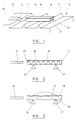
- FIG. 1 of the drawings there is shown a semiconductor substrate 10 which has been micromachined to form a vibrating sensor.
- a portion 11 of the substrate 10 is formed with a V-shaped groove 13 which is provided with an end stop 14.
- An optical fibre 15 is bonded into the groove 13, and its end abuts the end stop 14.
- a portion 12 of the semiconductor substrate is formed with two supports 16, 17 which lie across the width of the substrate.
- the supports 16, 17 taper towards their upper edges and support an optically transparent beam 18.
- the beam 18 lies perpendicular to the supports 16, 17 and these are inset from the opposite ends of the beam.
- the beam 18 is aligned on the same axis as the groove 13 and its optical fibre 15.
- the end of the optical fibre 15 is therefore directed at an end face 20 of the beam 18.
- the opposite ends 20, 21 of the beam 18 are polished or coated to render them semi-reflective, or the micromachining process may leave them in appropriate polished condition.
- the upper surface of the beam 18 has a thin layer of optically absorbent material 19 formed on it.
- monochromatic or narrow bandwidth light is transmitted down the optical fibre 15 from a light source 40, as shown in Figure 4.
- the light emitted from the fibre 15 is coupled into the end of the optically transparent beam 18.
- the beam 18 forms a Fabry-Perot interferometer cavity between its semi-reflective end faces 20, 21. Any light of the resonant wavelength entering the cavity will be reflected between the two surfaces 20, 21 and the light internally reflected from one such surface will interfere with the light incident on that surface: if the reflected and incident light waves are in phase (as shown in Figure 2) then they will constructively interfere and produce light of a higher intensity. If they are out of phase then they will partially cancel each other out and reduce the intensity of light passing lengthwise within the beam 18.
- the length of the beam 18 is such that, at rest, the incident and reflected waves constructively interfere.
- the resulting high light intensity is absorbed by the absorbent material 19 formed on the upper surface of the beam.
- This causes the beam 18 to be heated adjacent its upper surface, causing the beam to expand in length adjacent its upper surface and therefore the beam bends.
- the distance between the two reflective surfaces 20, 21 increases, so that the incident and reflected light waves becomes out of phase and the absorbent layer 19 and adjacent region of the beam cool. As this cooling occurs the beam returns to its original position. The process then repeats itself: as a result the beam vibrates at a resonant frequency.
- the absorbent layer may comprise a material which better absorbs a particular frequency of light than other frequencies.
- the layer preferentially absorbs light of the near infrared frequency. This selective absorption characteristic may be achieved by applying an optical filter layer between the surface of the beam and the absorbing layer.
- the absorbing layer may have a characteristic such that its absorption decreases with increasing wavelength.
- the standing wave between the opposite ends of the beam is based on progressively longer wavelengths: the energy absorbed therefore decreases progressively as the beam bends, causing it to cool in due course and restore.
- FIG 3 shows the beam 18 at different positions during its cycle of vibration, but exaggerated for the sake of illustration.
- the beam bends from its at-rest position (solid line) to an excited position (broken line 30) as it is heated. Then as it cools the beam 18 restores to its rest position.
- the beam may be caused to vibrate by modulation of the intensity of light which is coupled into the beam rather than using the effect of the Fabry-Perot interferometer.
- the Fabry-Perot interferometer effect is inhibited by using a broadband optical source.
- FIG 3 it can be seen that as the beam 18 bends due to light being absorbed by the absorbent layer 19, less light is coupled into the end of the beam 18 from the optical fibre 15. The beam therefore cools and straightens again, whereupon more light is coupled into the beam and the process repeats itself: the effect is that the beam vibrates at a predetermined frequency. This mode of operation is simpler than the above-described mode.
- the beam 18 is caused to vibrate at a predetermined frequency as described above. Some of the incident light is reflected from the end surface 20 of the beam and returns up the optical fibre 15: the returning light has thus been modulated by the vibrating beam.
- a fibre optic Y-coupler 42 is used ( Figure 4) to separate the reflected beam and direct it to a detecting device 44.
- a semi-silvered beam splitting mirror may be used, instead of the Y-coupler 42, to separate the reflected beam.
- External stresses applied to the beam such as acceleration or pressure, cause the beam to change its frequency of vibration. This change in frequency is detected by the device 44 and measured from the modulated, reflected light returned through the optical fibre and from known data the magnitude of the applied stress can be calculated.
- the beams 18 of a plurality of sensors may be coupled to a common optical fibre 15, the different sensors being excited by different wavelengths of light.
- the plurality of beams 18 may be formed on a single substrate.
- the intensity of the beam returned up the optical fibre is monitored by the detecting device 44 at the different wavelengths to determine changes in frequency of vibration of the different sensor beams 18.
- the plurality of beams 18 may be arranged to have different natural resonant frequencies of mechanical vibration, but to be excited all by the same wavelength of light.
- the light source 40 in Figure 5 is a single wavelength source: the detecting device 44 includes a plurality of narrow bandpass filters, arranged to pass separate frequency bands centred on the respective natural resonant frequencies of the beams 18.
Landscapes
- Physics & Mathematics (AREA)
- General Physics & Mathematics (AREA)
- Optics & Photonics (AREA)
- Engineering & Computer Science (AREA)
- Acoustics & Sound (AREA)
- Multimedia (AREA)
- Measurement Of Mechanical Vibrations Or Ultrasonic Waves (AREA)
- Measuring Fluid Pressure (AREA)
- Investigating Or Analyzing Materials By The Use Of Ultrasonic Waves (AREA)
- Length Measuring Devices By Optical Means (AREA)
- Instruments For Measurement Of Length By Optical Means (AREA)
Claims (11)
- Vibrationssensor, enthaltend ein längliches Element (18), welches schwingungsfähig angeordnet ist, und eine Einrichtung (15) zum Einkoppeln elektromagnetischer Strahlung in ein Ende (20) des länglichen Elementes, wobei das längliche Element auf einer Längsfläche eine Schicht (19) besitzt, welche elektromagnetische Strahlung absorbiert, und das längliche Element (15) so angeordnet ist, daß es seine Gestalt verändert, wenn die Schicht (19) Strahlung absorbiert, wobei diese Veränderung die von der Schicht (19) absorbierte Strahlungsenergie verringert.
- Vibrationssensor nach Anspruch 1, bei welchem innerhalb des länglichen Elementes (18) zwischen seinen gegenüberliegenden Enden (20, 21) ein Fabry-Perot-Interferometer begrenzt ist, so daß die eintreffenden und reflektierten Wellen der elektromagnetischen Strahlung an jedem Ende des Elementes (18) konstruktiv interferieren, wenn sich das Element in seiner Ruhestellung befindet.
- Vibrationssensor nach Anspruch 1, bei welchem das längliche Element (18) so angeordnet ist, daß weniger elektromagnetische Strahlung in das Ende (20) des Elementes eingekoppelt wird, wenn es aus seiner Ruhestellung herauskommt.
- Vibrationssensor nach einem der vorhergehenden Ansprüche, bei welchem die absorbierende Schicht (19) auf einer Längsseite des länglichen Elementes (18) aufgebracht ist, so daß Absorption von elektromagnetischer Strahlung durch die Schicht eine Erwärmung des länglichen Elementes (18) angrenzend an dessen Längsseite und damit eine Biegung des Elementes bewirkt.
- Vibrationssensor nach einem der vorhergehenden Ansprüche, bei welchem die absorbierende Schicht (19) elektromagnetische Strahlung einer bestimmten Frequenz absorbiert, die gegenüber anderen Frequenzen bevorzugt ist.
- Vibrationssensor nach einem der Ansprüche 1 bis 4, bei welchem die absorbierende Schicht (19) eine solche Eigenschaft besitzt, daß sie mit steigender Wellenlänge der Strahlung weniger absorbiert.
- Vibrationssensor nach einem der vorhergehenden Ansprüche, bei welchem die Einrichtung (15) zur Einkopplung elektromagnetischer Strahlung in das Ende (20) des länglichen Elementes eine optische Faser enthält, von der ein Ende auf das Ende (20) des länglichen Elementes gerichtet ist.
- Vibrationssensor nach einem der vorhergehenden Ansprüche, enthaltend eine Einrichtung zum Auffangen eines Teiles der elektromagnetischen Strahlung, welche von dem Ende (20) des länglichen Elementes (18) reflektiert wird, wobei der reflektierte Teil entsprechend der Schwingung des länglichen Elementes (18) moduliert ist und die Einrichtung auf den reflektierten Teil anspricht, um die Frequenzänderungen der Schwingung des länglichen Elementes (18) zu überwachen.
- Vibrationssensor nach einem der vorhergehenden Ansprüche, bei welchem das längliche Element einen Balken enthält, welcher durch Mikrobearbeitung aus einer Materialwafer hergestellt ist.
- Vibrationssensor nach einem der vorhergehenden Ansprüche, enthaltend eine Vielzahl von länglichen Elementen, die durch unterschiedliche Wellenlängen von elektromagnetischer Strahlung angeregt werden.
- Vibrationssensor nach einem der Ansprüche 1 bis 9, enthaltend eine Vielzahl von länglichen Elementen, die verschiedene Eigenresonanzfrequenzen der mechanischen Schwingung besitzen, wobei die länglichen Elemente von einer gemeinsamen Wellenlänge von elektromagnetische Strahlung angeregt werden.
Applications Claiming Priority (2)
| Application Number | Priority Date | Filing Date | Title |
|---|---|---|---|
| GB919105799A GB9105799D0 (en) | 1991-03-19 | 1991-03-19 | Vibrating sensor |
| GB9105799 | 1991-03-19 |
Publications (2)
| Publication Number | Publication Date |
|---|---|
| EP0505177A1 EP0505177A1 (de) | 1992-09-23 |
| EP0505177B1 true EP0505177B1 (de) | 1995-01-11 |
Family
ID=10691819
Family Applications (1)
| Application Number | Title | Priority Date | Filing Date |
|---|---|---|---|
| EP92302368A Expired - Lifetime EP0505177B1 (de) | 1991-03-19 | 1992-03-19 | Sensor mit einem schwingenden Element |
Country Status (5)
| Country | Link |
|---|---|
| US (1) | US5426981A (de) |
| EP (1) | EP0505177B1 (de) |
| JP (1) | JP3136308B2 (de) |
| DE (1) | DE69201153T2 (de) |
| GB (1) | GB9105799D0 (de) |
Families Citing this family (8)
| Publication number | Priority date | Publication date | Assignee | Title |
|---|---|---|---|---|
| US6246638B1 (en) * | 1999-03-30 | 2001-06-12 | Honeywell International Inc. | Fiber-optic vibration sensor based on frequency modulation of light-excited oscillators |
| DE60313327T2 (de) * | 2003-11-07 | 2007-12-27 | Varian S.P.A., Leini | Druckaufnehmer |
| CN101142642B (zh) | 2005-03-14 | 2010-05-19 | 株式会社村田制作所 | 叠层陶瓷电容器 |
| ITTO20050316A1 (it) | 2005-05-10 | 2006-11-11 | Varian Spa | Sensore di pressione |
| JPWO2007060742A1 (ja) | 2005-11-28 | 2009-05-07 | 三菱電機株式会社 | 印刷マスクおよび太陽電池セル |
| JP2007298368A (ja) * | 2006-04-28 | 2007-11-15 | Kyocera Corp | 光ファイバ圧力センサ |
| JP2010224665A (ja) * | 2009-03-19 | 2010-10-07 | Sony Corp | 光触覚変換システム、及び触覚フィードバックの提供方法 |
| CN112414597A (zh) * | 2020-11-05 | 2021-02-26 | 中国计量大学 | 一种基于锥腰嵌入凸泡的超高灵敏度光纤应力传感器 |
Family Cites Families (15)
| Publication number | Priority date | Publication date | Assignee | Title |
|---|---|---|---|---|
| US4300813A (en) * | 1979-09-04 | 1981-11-17 | Sperry Corporation | Fiber optic transducer and method of manufacture therefor |
| US4758087A (en) * | 1981-03-09 | 1988-07-19 | Polaroid Corporation | Fiber optic transducer |
| US4419896A (en) * | 1981-08-27 | 1983-12-13 | Olson Jr Carl O | Force or vibration indicating device utilizing microwave resonance ferramic gyrators |
| US4678905A (en) * | 1984-05-18 | 1987-07-07 | Luxtron Corporation | Optical sensors for detecting physical parameters utilizing vibrating piezoelectric elements |
| JPS622130A (ja) * | 1985-06-27 | 1987-01-08 | Sharp Corp | 応力検知装置 |
| GB8530809D0 (en) * | 1985-12-13 | 1986-01-22 | Gen Electric Co Plc | Sensor |
| GB8610253D0 (en) * | 1986-04-26 | 1986-05-29 | Stc Plc | Resonator device |
| GB2192456B (en) * | 1986-07-12 | 1990-07-04 | Stc Plc | Optical sensor |
| GB2198531B (en) * | 1986-12-13 | 1990-11-07 | Stc Plc | Optical sensor device |
| GB8701556D0 (en) * | 1987-01-24 | 1987-02-25 | Schlumberger Electronics Uk | Sensors |
| GB8705151D0 (en) * | 1987-03-05 | 1987-04-08 | Univ Strathclyde | Optically excited vibratile transducer |
| GB2213588B (en) * | 1987-12-08 | 1991-07-31 | Plessey Co Plc | Improvements relating to optical sensors |
| GB2215055B (en) * | 1988-02-20 | 1992-04-01 | Stc Plc | Optical fibre sensor |
| US4972076A (en) * | 1988-09-29 | 1990-11-20 | Schlumberger Industries Limited | Solid state sensor with dual resonant vibratable members |
| US5195374A (en) * | 1989-08-30 | 1993-03-23 | Schlumberger Industries Limited | Sensor systems |
-
1991
- 1991-03-19 GB GB919105799A patent/GB9105799D0/en active Pending
-
1992
- 1992-03-18 US US07/853,144 patent/US5426981A/en not_active Expired - Fee Related
- 1992-03-19 JP JP04062866A patent/JP3136308B2/ja not_active Expired - Fee Related
- 1992-03-19 DE DE69201153T patent/DE69201153T2/de not_active Expired - Fee Related
- 1992-03-19 EP EP92302368A patent/EP0505177B1/de not_active Expired - Lifetime
Also Published As
| Publication number | Publication date |
|---|---|
| US5426981A (en) | 1995-06-27 |
| EP0505177A1 (de) | 1992-09-23 |
| DE69201153T2 (de) | 1995-05-11 |
| JP3136308B2 (ja) | 2001-02-19 |
| DE69201153D1 (de) | 1995-02-23 |
| GB9105799D0 (en) | 1991-06-12 |
| JPH0587647A (ja) | 1993-04-06 |
Similar Documents
| Publication | Publication Date | Title |
|---|---|---|
| KR870001580B1 (ko) | 수동 간섭계식 감지기 어레이 | |
| KR940011933B1 (ko) | 측정자를 감지하기 위한 장치 및 방법 | |
| US5832157A (en) | Fiber optic acoustic emission sensor | |
| US5153771A (en) | Coherent light modulation and detector | |
| EP0331671B1 (de) | Selbstoszillierender, optischer resonanz sensor | |
| US4772786A (en) | Photothermal oscillator force sensor | |
| CA1278715C (en) | Fiber fabry-perot etalon | |
| US5105665A (en) | Sensors | |
| GB2146120A (en) | Photoacoustic force sensor | |
| US5426981A (en) | Vibrating sensor | |
| US5195374A (en) | Sensor systems | |
| US6097478A (en) | Fiber optic acoustic emission sensor | |
| GB2161931A (en) | Remote sensor systems | |
| EP0334481A1 (de) | Optischer Fibersensor | |
| US4600307A (en) | Coherent radiation detecting apparatus | |
| EP0435553B1 (de) | System mit optischem Sensor | |
| US4717240A (en) | Interferometeric beamsplitter | |
| US5513533A (en) | Detection of vibrational energy via optical interference patterns | |
| US5265479A (en) | Micro resonator | |
| US5447075A (en) | Self-exciting optical strain gage | |
| US5136607A (en) | Sensor for detecting a physical magnitude comprising a mechanical resonator | |
| JPH0752118B2 (ja) | 測定装置 | |
| GB2235773A (en) | Indirectly excited resonant element sensor | |
| JP2726860B2 (ja) | 光式振動形力センサ | |
| Duggal et al. | Optical detection of ultrasound using a microchip laser |
Legal Events
| Date | Code | Title | Description |
|---|---|---|---|
| PUAI | Public reference made under article 153(3) epc to a published international application that has entered the european phase |
Free format text: ORIGINAL CODE: 0009012 |
|
| AK | Designated contracting states |
Kind code of ref document: A1 Designated state(s): DE FR GB IT |
|
| 17P | Request for examination filed |
Effective date: 19930308 |
|
| 17Q | First examination report despatched |
Effective date: 19940519 |
|
| GRAA | (expected) grant |
Free format text: ORIGINAL CODE: 0009210 |
|
| AK | Designated contracting states |
Kind code of ref document: B1 Designated state(s): DE FR GB IT |
|
| ITF | It: translation for a ep patent filed | ||
| REF | Corresponds to: |
Ref document number: 69201153 Country of ref document: DE Date of ref document: 19950223 |
|
| ET | Fr: translation filed | ||
| PLBE | No opposition filed within time limit |
Free format text: ORIGINAL CODE: 0009261 |
|
| STAA | Information on the status of an ep patent application or granted ep patent |
Free format text: STATUS: NO OPPOSITION FILED WITHIN TIME LIMIT |
|
| 26N | No opposition filed | ||
| REG | Reference to a national code |
Ref country code: GB Ref legal event code: 732E |
|
| REG | Reference to a national code |
Ref country code: GB Ref legal event code: IF02 |
|
| PGFP | Annual fee paid to national office [announced via postgrant information from national office to epo] |
Ref country code: FR Payment date: 20020312 Year of fee payment: 11 |
|
| PGFP | Annual fee paid to national office [announced via postgrant information from national office to epo] |
Ref country code: GB Payment date: 20020320 Year of fee payment: 11 |
|
| PGFP | Annual fee paid to national office [announced via postgrant information from national office to epo] |
Ref country code: DE Payment date: 20020327 Year of fee payment: 11 |
|
| PG25 | Lapsed in a contracting state [announced via postgrant information from national office to epo] |
Ref country code: GB Free format text: LAPSE BECAUSE OF NON-PAYMENT OF DUE FEES Effective date: 20030319 |
|
| PG25 | Lapsed in a contracting state [announced via postgrant information from national office to epo] |
Ref country code: DE Free format text: LAPSE BECAUSE OF NON-PAYMENT OF DUE FEES Effective date: 20031001 |
|
| GBPC | Gb: european patent ceased through non-payment of renewal fee |
Effective date: 20030319 |
|
| PG25 | Lapsed in a contracting state [announced via postgrant information from national office to epo] |
Ref country code: FR Free format text: LAPSE BECAUSE OF NON-PAYMENT OF DUE FEES Effective date: 20031127 |
|
| REG | Reference to a national code |
Ref country code: FR Ref legal event code: ST |
|
| PG25 | Lapsed in a contracting state [announced via postgrant information from national office to epo] |
Ref country code: IT Free format text: LAPSE BECAUSE OF NON-PAYMENT OF DUE FEES;WARNING: LAPSES OF ITALIAN PATENTS WITH EFFECTIVE DATE BEFORE 2007 MAY HAVE OCCURRED AT ANY TIME BEFORE 2007. THE CORRECT EFFECTIVE DATE MAY BE DIFFERENT FROM THE ONE RECORDED. Effective date: 20050319 |