EP0331671B1 - Selbstoszillierender, optischer resonanz sensor - Google Patents
Selbstoszillierender, optischer resonanz sensor Download PDFInfo
- Publication number
- EP0331671B1 EP0331671B1 EP87906485A EP87906485A EP0331671B1 EP 0331671 B1 EP0331671 B1 EP 0331671B1 EP 87906485 A EP87906485 A EP 87906485A EP 87906485 A EP87906485 A EP 87906485A EP 0331671 B1 EP0331671 B1 EP 0331671B1
- Authority
- EP
- European Patent Office
- Prior art keywords
- resonator
- optical
- optical power
- light
- fabry
- Prior art date
- Legal status (The legal status is an assumption and is not a legal conclusion. Google has not performed a legal analysis and makes no representation as to the accuracy of the status listed.)
- Expired
Links
- 230000003287 optical effect Effects 0.000 title claims description 74
- 230000033001 locomotion Effects 0.000 claims description 28
- 238000000034 method Methods 0.000 claims description 28
- 239000013307 optical fiber Substances 0.000 claims description 25
- 239000000835 fiber Substances 0.000 claims description 18
- 230000000694 effects Effects 0.000 claims description 16
- 230000037361 pathway Effects 0.000 claims description 13
- 230000010355 oscillation Effects 0.000 claims description 11
- 238000005259 measurement Methods 0.000 claims description 10
- 238000006243 chemical reaction Methods 0.000 claims description 9
- 238000005305 interferometry Methods 0.000 claims description 4
- 230000002459 sustained effect Effects 0.000 claims description 4
- 239000010409 thin film Substances 0.000 claims description 3
- 238000009501 film coating Methods 0.000 claims 2
- 238000013461 design Methods 0.000 abstract description 5
- 230000004907 flux Effects 0.000 description 26
- 239000010408 film Substances 0.000 description 21
- 238000000576 coating method Methods 0.000 description 18
- 239000011248 coating agent Substances 0.000 description 15
- 229910052751 metal Inorganic materials 0.000 description 14
- 239000002184 metal Substances 0.000 description 14
- VYPSYNLAJGMNEJ-UHFFFAOYSA-N silicon dioxide Inorganic materials O=[Si]=O VYPSYNLAJGMNEJ-UHFFFAOYSA-N 0.000 description 13
- 239000000758 substrate Substances 0.000 description 12
- 230000006870 function Effects 0.000 description 11
- 239000000463 material Substances 0.000 description 10
- 238000002310 reflectometry Methods 0.000 description 7
- 239000005350 fused silica glass Substances 0.000 description 6
- ZOKXTWBITQBERF-UHFFFAOYSA-N Molybdenum Chemical compound [Mo] ZOKXTWBITQBERF-UHFFFAOYSA-N 0.000 description 5
- 238000004891 communication Methods 0.000 description 5
- 238000001514 detection method Methods 0.000 description 5
- 230000007246 mechanism Effects 0.000 description 5
- 229910052750 molybdenum Inorganic materials 0.000 description 5
- 239000011733 molybdenum Substances 0.000 description 5
- 230000008569 process Effects 0.000 description 5
- 235000012239 silicon dioxide Nutrition 0.000 description 5
- 229910052984 zinc sulfide Inorganic materials 0.000 description 5
- XUIMIQQOPSSXEZ-UHFFFAOYSA-N Silicon Chemical compound [Si] XUIMIQQOPSSXEZ-UHFFFAOYSA-N 0.000 description 4
- GWEVSGVZZGPLCZ-UHFFFAOYSA-N Titan oxide Chemical compound O=[Ti]=O GWEVSGVZZGPLCZ-UHFFFAOYSA-N 0.000 description 4
- 239000005083 Zinc sulfide Substances 0.000 description 4
- 230000008859 change Effects 0.000 description 4
- 238000004519 manufacturing process Methods 0.000 description 4
- 229910052710 silicon Inorganic materials 0.000 description 4
- 239000010703 silicon Substances 0.000 description 4
- DRDVZXDWVBGGMH-UHFFFAOYSA-N zinc;sulfide Chemical compound [S-2].[Zn+2] DRDVZXDWVBGGMH-UHFFFAOYSA-N 0.000 description 4
- 230000001133 acceleration Effects 0.000 description 3
- 239000002131 composite material Substances 0.000 description 3
- 230000006835 compression Effects 0.000 description 3
- 238000007906 compression Methods 0.000 description 3
- 229910001635 magnesium fluoride Inorganic materials 0.000 description 3
- 239000010453 quartz Substances 0.000 description 3
- 238000005452 bending Methods 0.000 description 2
- 230000008901 benefit Effects 0.000 description 2
- 230000005540 biological transmission Effects 0.000 description 2
- 230000001427 coherent effect Effects 0.000 description 2
- 230000000295 complement effect Effects 0.000 description 2
- 239000013078 crystal Substances 0.000 description 2
- 238000010586 diagram Methods 0.000 description 2
- 230000004069 differentiation Effects 0.000 description 2
- 239000012530 fluid Substances 0.000 description 2
- 238000010438 heat treatment Methods 0.000 description 2
- 230000006872 improvement Effects 0.000 description 2
- ORUIBWPALBXDOA-UHFFFAOYSA-L magnesium fluoride Chemical compound [F-].[F-].[Mg+2] ORUIBWPALBXDOA-UHFFFAOYSA-L 0.000 description 2
- 230000010287 polarization Effects 0.000 description 2
- 238000004886 process control Methods 0.000 description 2
- 230000035945 sensitivity Effects 0.000 description 2
- 239000000377 silicon dioxide Substances 0.000 description 2
- XLOMVQKBTHCTTD-UHFFFAOYSA-N Zinc monoxide Chemical compound [Zn]=O XLOMVQKBTHCTTD-UHFFFAOYSA-N 0.000 description 1
- 230000002730 additional effect Effects 0.000 description 1
- 229910052681 coesite Inorganic materials 0.000 description 1
- 229910052906 cristobalite Inorganic materials 0.000 description 1
- 230000007423 decrease Effects 0.000 description 1
- 230000001066 destructive effect Effects 0.000 description 1
- 239000003989 dielectric material Substances 0.000 description 1
- 230000005611 electricity Effects 0.000 description 1
- 230000005670 electromagnetic radiation Effects 0.000 description 1
- 238000002474 experimental method Methods 0.000 description 1
- 239000007789 gas Substances 0.000 description 1
- 239000007788 liquid Substances 0.000 description 1
- 230000004048 modification Effects 0.000 description 1
- 238000012986 modification Methods 0.000 description 1
- 230000004044 response Effects 0.000 description 1
- 238000012552 review Methods 0.000 description 1
- 238000000926 separation method Methods 0.000 description 1
- 239000002210 silicon-based material Substances 0.000 description 1
- 229910052682 stishovite Inorganic materials 0.000 description 1
- 239000004408 titanium dioxide Substances 0.000 description 1
- 238000012546 transfer Methods 0.000 description 1
- 229910052905 tridymite Inorganic materials 0.000 description 1
Images



Classifications
-
- G—PHYSICS
- G01—MEASURING; TESTING
- G01D—MEASURING NOT SPECIALLY ADAPTED FOR A SPECIFIC VARIABLE; ARRANGEMENTS FOR MEASURING TWO OR MORE VARIABLES NOT COVERED IN A SINGLE OTHER SUBCLASS; TARIFF METERING APPARATUS; MEASURING OR TESTING NOT OTHERWISE PROVIDED FOR
- G01D5/00—Mechanical means for transferring the output of a sensing member; Means for converting the output of a sensing member to another variable where the form or nature of the sensing member does not constrain the means for converting; Transducers not specially adapted for a specific variable
- G01D5/26—Mechanical means for transferring the output of a sensing member; Means for converting the output of a sensing member to another variable where the form or nature of the sensing member does not constrain the means for converting; Transducers not specially adapted for a specific variable characterised by optical transfer means, i.e. using infrared, visible, or ultraviolet light
- G01D5/268—Mechanical means for transferring the output of a sensing member; Means for converting the output of a sensing member to another variable where the form or nature of the sensing member does not constrain the means for converting; Transducers not specially adapted for a specific variable characterised by optical transfer means, i.e. using infrared, visible, or ultraviolet light using optical fibres
-
- G—PHYSICS
- G01—MEASURING; TESTING
- G01D—MEASURING NOT SPECIALLY ADAPTED FOR A SPECIFIC VARIABLE; ARRANGEMENTS FOR MEASURING TWO OR MORE VARIABLES NOT COVERED IN A SINGLE OTHER SUBCLASS; TARIFF METERING APPARATUS; MEASURING OR TESTING NOT OTHERWISE PROVIDED FOR
- G01D5/00—Mechanical means for transferring the output of a sensing member; Means for converting the output of a sensing member to another variable where the form or nature of the sensing member does not constrain the means for converting; Transducers not specially adapted for a specific variable
- G01D5/26—Mechanical means for transferring the output of a sensing member; Means for converting the output of a sensing member to another variable where the form or nature of the sensing member does not constrain the means for converting; Transducers not specially adapted for a specific variable characterised by optical transfer means, i.e. using infrared, visible, or ultraviolet light
- G01D5/266—Mechanical means for transferring the output of a sensing member; Means for converting the output of a sensing member to another variable where the form or nature of the sensing member does not constrain the means for converting; Transducers not specially adapted for a specific variable characterised by optical transfer means, i.e. using infrared, visible, or ultraviolet light by interferometric means
-
- G—PHYSICS
- G01—MEASURING; TESTING
- G01H—MEASUREMENT OF MECHANICAL VIBRATIONS OR ULTRASONIC, SONIC OR INFRASONIC WAVES
- G01H13/00—Measuring resonant frequency
-
- G—PHYSICS
- G01—MEASURING; TESTING
- G01H—MEASUREMENT OF MECHANICAL VIBRATIONS OR ULTRASONIC, SONIC OR INFRASONIC WAVES
- G01H9/00—Measuring mechanical vibrations or ultrasonic, sonic or infrasonic waves by using radiation-sensitive means, e.g. optical means
- G01H9/004—Measuring mechanical vibrations or ultrasonic, sonic or infrasonic waves by using radiation-sensitive means, e.g. optical means using fibre optic sensors
Definitions
- process control includes both individual variable processes and complex multivariable processes involving a large number of controlled process conditions characterizable as physical parameters or “measurands”, such as acceleration fluid, flow, flow rate, temperature, pressure, differential pressure, level, and the equivalents and derivatives thereof.
- "Resonant mechanical structure”, “resonator”, and “resonant element” as used herein generally refer to beam (hollow beam, cantilevered beam and cantilevered hollow beam, and double- or other multiple-beam elements), and ribbon, wire or other articles of manufacture, and their equivalents, all of which can be resonated at particular oscillation frequencies.
- tuning fork structures of the single- and double-ended varieties, as well as multiple tine tuning fork structures are included.
- Fiber optic means and equivalent terms refer to single or multiple mode fiber optic communication paths.
- optical power includes electromagnetic radiation of wavelengths between 0.1 and 100 micrometers, and specifically includes infrared, ultraviolet, and visible electromagnetic radiated power.
- electromagnetic radiated power may be referred to generally and without limitation as “light”, optical flux, or optical power.
- Such optical power may also be described as “steady” or “continuous” or “unmodulated” in order to distinguish it from optical power signals which are modified to carry information.
- optical power specifically includes coherent and incoherent light power.
- Photothermal effect and “photokinetic effect”, as used herein, refer to the phenomenon wherein photons striking a suitable surface or surface coating cause localized heating, such heating being sufficient to cause localized expansion of the coating or substrate and thereby producing motion.
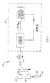
- the invention therefore relates to a self-oscillating, optically powered resonant sensor located in the process environment and configured to sense a measurand of interest such as pressure, differential pressure, force, acceleration, or temperature.
- a source of unmodulated optical power conveys optical power to the sensor site, preferably via a optical fiber.
- the optical power source may be located remotely in a suitable place, such as a control room, along with detection means to receive back-reflected, modulated optical power by way of the fiber and a fiber splitter. That is, modulated power in which the modulation is related to the measurand is reflected back along the same optical fiber to the remote location.
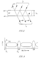
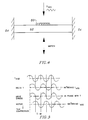
- a self-oscillating resonant transducer may be provided for using an interferometric technique in which the motion of a vibrating resonant mechanical structure efficiently modulates a portion of the received optical power and, advantageously, converts a portion of the modulated light into mechanical energy of resonator vibration. This may be accomplished in such a way as to enhance, by local feedback, the resonant motion of the vibrating resonant element, thereby sustaining oscillation thereof.
- the self-oscillating optically powered resonant sensor 20 apart from sensing the measurand and returning an optical frequency signal, combines several novel functions.
- the motion of the vibrating structure efficiently modulates a portion of the received optical power by reflection.
- a portion of the modulated light is converted into resonantor mechanical energy of fibration by the photothermal effect previously described. This is accomplished in such a way as to enhance, by positive feedback, the resonant motion.
- the oscillation loop is closed at the measurement site.
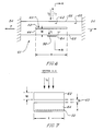
- Fig. 9 shows an alternate embodiment of the present invention in which the modulated transmitted light beam (I t ) exits the outer surface 68 of tine 64 and is absorbed by a photodetector 70 or other light-to-electrical power transducer such as a photocell. Surfaces 66 and 68 may be advantageously antireflection coated.
- the electrical energy produced by photodetector 70 may be used to drive the resonator 60 via impedance matching transformer 67.
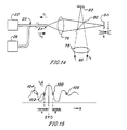
- FIG. 12 shows a simplified conventional Michelson interferometer.
- Unmodulated optical power from a light source (not shown) is supplied via an optical fiber 24 and collimated by lens 76.
- This input light beam here shown as light flux (I0) is split by beamsplitter 80 which may conveniently be a conventional cube beamsplitter.
- Light flux (I0) is divided into two equal portions without polarization preference for the purposes of this embodiment.
- Mirrors 82 and 84 return light energy to the beamsplitter. Two output beams result.
- One beam is collected by lens 78 which exits as transmitted light flux 86 beam (I t ).
- the other beam (reflected beam I r ) is returned via optical fiber 24 pathway.
- the modulated output beam should be used to drive the resonant element. This may be accomplished by directing the modulated light, for example, to a metal film on the resonator, where the metal film can couple the optical power to motion of the resonator by the photothermal effect. Alternatively, the light flux may be directed to and be absorbed by a photocell and converted to electric power. The electrical power may then be used to drive the resonator electromechanically or electromagnetically. The phase should be selected to optimize positive feedback.
- the resulting complementary modulated light beam, returned toward the source carries the modulating frequency, and thus is related to the sensed measurand information, back to the remotely located control room.
- the interferometer should be adjusted such that the output light beam I t delivered to coating 98 location is near the working point 100 on the interference pattern shown in FIG. 15).
- the resonator 90 in its at-rest condition may be about lambda/8 (i.e., one-eighth wavelength) nearer the beamsplitter than is the fixed mirror.
- Locations such as working point 104 or 106 may be used but the maximum modulation and hence maximum gain factor G1 is achievable near point 100.
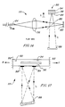
- the first preferred embodiment previously described uses a Fabry-Perot optical resonator integral with the mechanical resonant transducer. This arrangement has inherent rejection of common mode motions of the resonant transducer as a whole relative to the mounting structure and light delivery system. In the Michelson interferometeric-based technique, any motion of beamsplitter 80 and fixed mirror 82 relative to resonator 90 will result in unwanted modulation of the light.
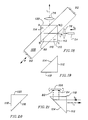
- the resonant element shown in FIG. 18 is a torsional ribbon resonator 108 such that, as the mirror 82 reflecting surface (see FIG. 21) moves toward the beamsplitter prism 110, mirror 84 reflecting surface moves away.
- Common mode motion of the mirrors 82, 84 reflecting surfaces together affects both arms of the interferometric arrangement equally so as not to contribute to light modulation.
- the desired torsional mode has a push-pull effect on the interferometer arms and results in double the modulation sensitivity compared with the arrangement in FIGS. 16 and 17.
- the input (I0) and exit (I t ) paths can be made (by refraction) to lie along the axis of the resonator and so produce a very compact optical sensor package.
- a Michelson interferometer can be constructed using optical fibers and a fiber splitter so as to eliminate the need for bulk optic components.
- the optical fibers transporting the split beams may terminate close to reflective locations on the resonator and so sense differential motion while discriminating against common mode undesired motions.
- the apparatus of FIG. 23 operates with a steady light source 22 providing a beam of steady light along fiber optic pathway 24 to four-port coupler 131 at entry port t, in which coupler the incoming light is split into two pathways internally to shine on mirrors 82 and 84 via ports v and w, respectively.
- the mirrors 82 and 84 are surface areas on resonator 108. Alternating torsional oscillations of the resonator 108 vary the light reflected by the mirrors (i.e. modulate the light according to the oscillation frequency of the resonator) back into ports v and w.
- the resonant frequency of resonator 108 may be varied in relation to an external value, which may be a measurand.
- a portion of the modulated light is returned along fiber optic 24 pathway carrying the frequency of the resonator and another portion is used to drive the resonator by positive feedback by fiber optic 133 pathway.
- This latter portion of the modulated light is used to drive the resonator 108 into resonant vibrations, such as by the photokinetic effect previously described, or such other methods as are known to those persons skilled in the art.
Landscapes
- Physics & Mathematics (AREA)
- General Physics & Mathematics (AREA)
- Instruments For Measurement Of Length By Optical Means (AREA)
- Mechanical Light Control Or Optical Switches (AREA)
Claims (19)
Applications Claiming Priority (1)
| Application Number | Priority Date | Filing Date | Title |
|---|---|---|---|
| US06/888,555 US4733561A (en) | 1986-07-21 | 1986-07-21 | Self-oscillating, optical resonant sensor |
Publications (2)
| Publication Number | Publication Date |
|---|---|
| EP0331671A1 EP0331671A1 (de) | 1989-09-13 |
| EP0331671B1 true EP0331671B1 (de) | 1992-06-17 |
Family
ID=25393395
Family Applications (1)
| Application Number | Title | Priority Date | Filing Date |
|---|---|---|---|
| EP87906485A Expired EP0331671B1 (de) | 1986-07-21 | 1987-07-22 | Selbstoszillierender, optischer resonanz sensor |
Country Status (6)
| Country | Link |
|---|---|
| US (1) | US4733561A (de) |
| EP (1) | EP0331671B1 (de) |
| CN (1) | CN1010346B (de) |
| CA (1) | CA1334053C (de) |
| DE (1) | DE3779928T2 (de) |
| WO (1) | WO1989000677A1 (de) |
Families Citing this family (37)
| Publication number | Priority date | Publication date | Assignee | Title |
|---|---|---|---|---|
| US4897541A (en) * | 1984-05-18 | 1990-01-30 | Luxtron Corporation | Sensors for detecting electromagnetic parameters utilizing resonating elements |
| US4899044A (en) * | 1988-04-29 | 1990-02-06 | Westinghouse Electric Corp. | Optically coupled remote sensor apparatus and system |
| WO1992002912A1 (en) * | 1990-08-06 | 1992-02-20 | Schier J Alan | Sensing apparatus |
| US5162872A (en) * | 1991-07-02 | 1992-11-10 | The United States Of America As Represented The Secretary Of The Air Force | Tilt/shear immune tunable fabry-perot interferometer |
| US5559358A (en) * | 1993-05-25 | 1996-09-24 | Honeywell Inc. | Opto-electro-mechanical device or filter, process for making, and sensors made therefrom |
| US5367583A (en) * | 1994-02-09 | 1994-11-22 | University Of Maryland | Fiber optic stress-corrosion sensor and system |
| US5698848A (en) * | 1995-06-07 | 1997-12-16 | Mcdonnell Douglas Corporation | Fiber optic sensing systems and methods including contiguous optical cavities |
| US5727110A (en) * | 1995-09-29 | 1998-03-10 | Rosemount Inc. | Electro-optic interface for field instrument |
| US5771114A (en) * | 1995-09-29 | 1998-06-23 | Rosemount Inc. | Optical interface with safety shutdown |
| RU2135958C1 (ru) * | 1997-06-26 | 1999-08-27 | Московский государственный университет леса | Волоконно-оптический автогенератор |
| RU2142114C1 (ru) * | 1998-07-30 | 1999-11-27 | Московский государственный университет леса | Микрорезонаторный волоконно-оптический датчик концентрации газов |
| RU2142116C1 (ru) * | 1998-09-17 | 1999-11-27 | Московский государственный университет леса | Микрорезонаторный волоконно-оптический датчик линейных перемещений |
| US7800758B1 (en) * | 1999-07-23 | 2010-09-21 | Faro Laser Trackers, Llc | Laser-based coordinate measuring device and laser-based method for measuring coordinates |
| RU2157512C1 (ru) * | 1999-12-28 | 2000-10-10 | Московский государственный университет леса | Микрорезонаторный волоконно-оптический датчик магнитных полей |
| RU2163354C1 (ru) * | 1999-12-28 | 2001-02-20 | Московский государственный университет леса | Волоконно-оптический автогенератор |
| US7134341B2 (en) * | 2003-04-28 | 2006-11-14 | Zuli Holdings Ltd | Methods and devices for determining the resonance frequency of passive mechanical resonators |
| US7415883B2 (en) * | 2004-06-28 | 2008-08-26 | Zuli Holdings Ltd | Method for protecting resonating sensors and open protected resonating sensors |
| US8162839B2 (en) * | 2003-08-27 | 2012-04-24 | Microtech Medical Technologies Ltd. | Protected passive resonating sensors |
| US6999221B1 (en) | 2003-11-17 | 2006-02-14 | Alabama A&M University | Bimorphic polymeric photomechanical actuator |
| US7307540B2 (en) * | 2004-06-08 | 2007-12-11 | General Electric Company | Systems, apparatus, and methods having a mechanical logic function in a microelectromechanical system sensor |
| US7155077B1 (en) * | 2005-06-21 | 2006-12-26 | Agilent Technologies, Inc | Optical fiber based surface sensing system that enables spectral multiplexing |
| GB2508908B (en) | 2012-12-14 | 2017-02-15 | Gen Electric | Resonator device |
| GB2509105B (en) * | 2012-12-20 | 2017-02-22 | Oxsensis Ltd | Mechanical resonator sensor |
| US9527733B2 (en) | 2014-11-07 | 2016-12-27 | The Chinese University Of Hong Kong | Method and apparatus for dynamic-tuning |
| FR3072512B1 (fr) * | 2017-10-17 | 2021-06-11 | Thales Sa | Oscillateur radiofrequence ameliore |
| US10830787B2 (en) * | 2018-02-20 | 2020-11-10 | General Electric Company | Optical accelerometers for use in navigation grade environments |
| EP3624510A1 (de) * | 2018-09-17 | 2020-03-18 | KNORR-BREMSE Systeme für Nutzfahrzeuge GmbH | Vorrichtung und verfahren zur synchronisierung von endknoten |
| US11079227B2 (en) | 2019-04-01 | 2021-08-03 | Honeywell International Inc. | Accelerometer system enclosing gas |
| US11119116B2 (en) | 2019-04-01 | 2021-09-14 | Honeywell International Inc. | Accelerometer for determining an acceleration based on modulated optical signals |
| US10705112B1 (en) | 2019-04-22 | 2020-07-07 | Honeywell International Inc. | Noise rejection for optomechanical devices |
| US10956768B2 (en) | 2019-04-22 | 2021-03-23 | Honeywell International Inc. | Feedback cooling and detection for optomechanical devices |
| CN109975577B (zh) * | 2019-04-22 | 2024-01-26 | 东南大学 | 基于弱耦合谐振器的微机械毛发流速传感器及其运行方法 |
| US11408911B2 (en) | 2019-07-17 | 2022-08-09 | Honeywell International Inc. | Optomechanical structure with corrugated edge |
| US11119114B2 (en) | 2019-07-17 | 2021-09-14 | Honeywell International Inc. | Anchor structure for securing optomechanical structure |
| US11408912B2 (en) | 2019-08-13 | 2022-08-09 | Honeywell International Inc. | Feedthrough rejection for optomechanical devices |
| US11150264B2 (en) | 2019-08-13 | 2021-10-19 | Honeywell International Inc. | Feedthrough rejection for optomechanical devices using elements |
| US11372019B2 (en) | 2019-08-13 | 2022-06-28 | Honeywell International Inc. | Optomechanical resonator stabilization for optomechanical devices |
Family Cites Families (8)
| Publication number | Priority date | Publication date | Assignee | Title |
|---|---|---|---|---|
| SE414672B (sv) * | 1978-11-16 | 1980-08-11 | Asea Ab | Fiberoptiskt don for metning av fysikaliska storheter sasom kraft, tojning, tryck, acceleration och temperatur |
| US4553247A (en) * | 1981-11-20 | 1985-11-12 | Gould Inc. | Telemetry system with signal booster for digital data transmission through a transmission line |
| US4521684A (en) * | 1982-02-22 | 1985-06-04 | The Foxboro Company | Optical measurement system with light-driven vibrating sensor element |
| US4556280A (en) * | 1983-09-13 | 1985-12-03 | United States Riley Corporation | Single cable optical fibre signaling system |
| US4577100A (en) * | 1983-12-27 | 1986-03-18 | United Technologies Corporation | Temperature compensated optical pressure sensor |
| EP0181397A1 (de) * | 1984-05-07 | 1986-05-21 | The Foxboro Company | Verbesserter sensor mit lichtwellenleitern zum fernmessen |
| GB8504987D0 (en) * | 1985-02-27 | 1985-03-27 | Univ Strathclyde | Measuring device |
| US4713540A (en) * | 1985-07-16 | 1987-12-15 | The Foxboro Company | Method and apparatus for sensing a measurand |
-
1986
- 1986-07-21 US US06/888,555 patent/US4733561A/en not_active Expired - Fee Related
-
1987
- 1987-07-20 CA CA000542483A patent/CA1334053C/en not_active Expired - Fee Related
- 1987-07-20 CN CN87105179A patent/CN1010346B/zh not_active Expired
- 1987-07-22 EP EP87906485A patent/EP0331671B1/de not_active Expired
- 1987-07-22 WO PCT/US1987/001783 patent/WO1989000677A1/en not_active Ceased
- 1987-07-22 DE DE8787906485T patent/DE3779928T2/de not_active Expired - Fee Related
Also Published As
| Publication number | Publication date |
|---|---|
| CA1334053C (en) | 1995-01-24 |
| US4733561A (en) | 1988-03-29 |
| EP0331671A1 (de) | 1989-09-13 |
| DE3779928D1 (de) | 1992-07-23 |
| CN87105179A (zh) | 1988-02-03 |
| CN1010346B (zh) | 1990-11-07 |
| DE3779928T2 (de) | 1993-01-14 |
| WO1989000677A1 (en) | 1989-01-26 |
Similar Documents
| Publication | Publication Date | Title |
|---|---|---|
| US4733561A (en) | Self-oscillating, optical resonant sensor | |
| Lu et al. | Review of micromachined optical accelerometers: From mg to sub-μg | |
| US5091983A (en) | Optical modulation apparatus and measurement method | |
| US7428054B2 (en) | Micro-optical sensor system for pressure, acceleration, and pressure gradient measurements | |
| US4772786A (en) | Photothermal oscillator force sensor | |
| CN101608944B (zh) | 一种光纤振动传感头及其制作方法 | |
| US5017010A (en) | High sensitivity position sensor and method | |
| US4446543A (en) | Optical resonator single-mode fiber hydrophone | |
| Tudor et al. | Silicon resonator sensors: interrogation techniques and characteristics | |
| NO871064L (no) | Fremgangsmaate og apparat for avfoeling av en maalestoerrelse. | |
| Tabib-Azar et al. | Modern trends in microstructures and integrated optics for communication, sensing, and actuation | |
| GB2136952A (en) | Fabry perot sensor | |
| US4891512A (en) | Thermo-optic differential expansion fiber sensor | |
| Churenkov | Photothermal excitation and self-excitation of silicon microresonators | |
| US4717240A (en) | Interferometeric beamsplitter | |
| US5195374A (en) | Sensor systems | |
| US4600307A (en) | Coherent radiation detecting apparatus | |
| US5521884A (en) | Vibrating element transducer | |
| US7443509B1 (en) | Optical and electronic interface for optically coupled resonators | |
| US5265479A (en) | Micro resonator | |
| AU8022787A (en) | Self-oscillating, optical resonant sensor | |
| RU2117934C1 (ru) | Волоконно-оптический автогенератор | |
| WO1992001230A1 (en) | Velocimeters | |
| CN116773851B (zh) | 基于储备池腔光增强的腔光力学mems加速度传感器 | |
| JP2726860B2 (ja) | 光式振動形力センサ |
Legal Events
| Date | Code | Title | Description |
|---|---|---|---|
| PUAI | Public reference made under article 153(3) epc to a published international application that has entered the european phase |
Free format text: ORIGINAL CODE: 0009012 |
|
| 17P | Request for examination filed |
Effective date: 19890714 |
|
| AK | Designated contracting states |
Kind code of ref document: A1 Designated state(s): DE FR GB |
|
| 17Q | First examination report despatched |
Effective date: 19891129 |
|
| GRAA | (expected) grant |
Free format text: ORIGINAL CODE: 0009210 |
|
| AK | Designated contracting states |
Kind code of ref document: B1 Designated state(s): DE FR GB |
|
| REF | Corresponds to: |
Ref document number: 3779928 Country of ref document: DE Date of ref document: 19920723 |
|
| ET | Fr: translation filed | ||
| PLBE | No opposition filed within time limit |
Free format text: ORIGINAL CODE: 0009261 |
|
| STAA | Information on the status of an ep patent application or granted ep patent |
Free format text: STATUS: NO OPPOSITION FILED WITHIN TIME LIMIT |
|
| 26N | No opposition filed | ||
| PGFP | Annual fee paid to national office [announced via postgrant information from national office to epo] |
Ref country code: GB Payment date: 19960617 Year of fee payment: 10 |
|
| PGFP | Annual fee paid to national office [announced via postgrant information from national office to epo] |
Ref country code: FR Payment date: 19960715 Year of fee payment: 10 |
|
| PGFP | Annual fee paid to national office [announced via postgrant information from national office to epo] |
Ref country code: DE Payment date: 19960730 Year of fee payment: 10 |
|
| PG25 | Lapsed in a contracting state [announced via postgrant information from national office to epo] |
Ref country code: GB Free format text: LAPSE BECAUSE OF NON-PAYMENT OF DUE FEES Effective date: 19970722 |
|
| GBPC | Gb: european patent ceased through non-payment of renewal fee |
Effective date: 19970722 |
|
| PG25 | Lapsed in a contracting state [announced via postgrant information from national office to epo] |
Ref country code: FR Free format text: LAPSE BECAUSE OF NON-PAYMENT OF DUE FEES Effective date: 19980331 |
|
| PG25 | Lapsed in a contracting state [announced via postgrant information from national office to epo] |
Ref country code: DE Free format text: LAPSE BECAUSE OF NON-PAYMENT OF DUE FEES Effective date: 19980401 |
|
| REG | Reference to a national code |
Ref country code: FR Ref legal event code: ST |