EP0504610A1 - Device for reducing current peaks during starting of an asynchronous motor - Google Patents
Device for reducing current peaks during starting of an asynchronous motor Download PDFInfo
- Publication number
- EP0504610A1 EP0504610A1 EP92102901A EP92102901A EP0504610A1 EP 0504610 A1 EP0504610 A1 EP 0504610A1 EP 92102901 A EP92102901 A EP 92102901A EP 92102901 A EP92102901 A EP 92102901A EP 0504610 A1 EP0504610 A1 EP 0504610A1
- Authority
- EP
- European Patent Office
- Prior art keywords
- winding
- motor
- accordance
- wire
- tubular body
- Prior art date
- Legal status (The legal status is an assumption and is not a legal conclusion. Google has not performed a legal analysis and makes no representation as to the accuracy of the status listed.)
- Granted
Links
- 238000004804 winding Methods 0.000 claims abstract description 29
- 239000002184 metal Substances 0.000 claims abstract description 8
- 229910052751 metal Inorganic materials 0.000 claims abstract description 8
- 239000012530 fluid Substances 0.000 claims abstract description 5
- 239000011810 insulating material Substances 0.000 claims abstract description 4
- RYGMFSIKBFXOCR-UHFFFAOYSA-N Copper Chemical compound [Cu] RYGMFSIKBFXOCR-UHFFFAOYSA-N 0.000 claims description 3
- 239000003638 chemical reducing agent Substances 0.000 claims description 2
- 238000010586 diagram Methods 0.000 description 3
- 230000004913 activation Effects 0.000 description 2
- 238000005293 physical law Methods 0.000 description 2
- 230000015572 biosynthetic process Effects 0.000 description 1
- 229910052802 copper Inorganic materials 0.000 description 1
- 239000010949 copper Substances 0.000 description 1
- 230000000694 effects Effects 0.000 description 1
- 238000010438 heat treatment Methods 0.000 description 1
- 238000012423 maintenance Methods 0.000 description 1
- 238000013021 overheating Methods 0.000 description 1
- 230000035945 sensitivity Effects 0.000 description 1
Images
Classifications
-
- H—ELECTRICITY
- H02—GENERATION; CONVERSION OR DISTRIBUTION OF ELECTRIC POWER
- H02K—DYNAMO-ELECTRIC MACHINES
- H02K17/00—Asynchronous induction motors; Asynchronous induction generators
- H02K17/02—Asynchronous induction motors
- H02K17/30—Structural association of asynchronous induction motors with auxiliary electric devices influencing the characteristics of the motor or controlling the motor, e.g. with impedances or switches
-
- H—ELECTRICITY
- H01—ELECTRIC ELEMENTS
- H01F—MAGNETS; INDUCTANCES; TRANSFORMERS; SELECTION OF MATERIALS FOR THEIR MAGNETIC PROPERTIES
- H01F37/00—Fixed inductances not covered by group H01F17/00
Definitions
- the present invention relates to a device for reducing current peaks during starting of an asynchronous electric motor.
- the present invention relates to a device for reducing current peaks during starting of an asynchronous electric motor for control of hydraulic elevators.
- Said starting causes considerable shortcomings and limitations in said asynchronous motors due to the fact that in case of direct starting the sudden drawing of current from the supply network is in general at least three times as much as normally required during operation of the motor.
- Star-triangle starting of an asynchronous motor is theoretically efficient but the motor is practically subjected to two starts. Indeed, the fluid operating it has a braking action during the exchange phase of the remote controlled switches and or switches so that initially and generally it includes a phase of insufficient power supply.
- Resistance starting of an asynchronous motor displays different shortcomings such as for example heating of the resistances, sensitivity of the resistances to voltage differences, possible slightly retarded changeover of the remote controlled switches with resulting burning of the resistances, etc. All of these shortcomings make this type of starting system, overall, unreliable and of relatively short life.
- the purpose of the present invention is to provide a device for starting asynchronous electric motors which would not have the above described shortcomings. More specifically, the purpose of the present invention is to provide a device designed to reduce current peaks during starting of asynchronous motors for control of hydraulic elevators.
- a device comprising substantially a metal nucleus inserted in a tubular body made of insulating material on which is arranged a copper wire winding connected to the phase of the motor and to a pair of switches and/or remote controlled switches respectively.
- Said winding material izes an inductance which maintains a value essentially less than the current taken from the electric power network during starting of the motor and this is based on well known physical laws (Faraday-Newman-Leinz) and in relation to the structural conformation of said inductance.
- the winding or inductance of the device is immersed in and cooled by the same operating fluid as the motor.
- the opposite ends of the tubular body are structurally formed in such a manner as to form a flange for containing the winding.
- metal nucleus is preferably traversed longitudinally by a passage which lightens its weight and can be positioned stably in the tubular body by Seger cones or equivalent means.
- the inductance can be provided by winding on the tubular body the same wire coming from the motor winding.
- the device (8) of the present invention comprises essentially a metal nucleus (10) inserted in a tubular body (12) made of insulating material, e.g. plastic, and bounded at its opposite ends by flanges (14,16).
- a winding (13) consisting of copper wires positioned stably by the flanges (14,16). Said winding (13) materializes an inductance connected to the winding of the motor and to a pair of switches and/or remote controlled switches as specified below.
- the winding or inductance (13) is preferably immersed in and cooled by the operating fluid of the motor which, in FIG. 1, is shown schematically in broken lines as a rectangle (11).
- the winding or inductance (13) can be provided by winding around the tubular body (12) the same wire coming from the motor winding.
- the metal nucleus (10) is stably positioned in the tubular body (12) by Seger cones (15) or equivalent means and traversed by a longitudinal passage (17) which reduces in this manner the total weight of the device (8).
- the device (8) provided in accordance with the present invention as described above is capable of eliminating or reducing considerably the known current peaks during starting of an asynchronous motor for control of hydraulic-traction elevators because it holds substantially always constant the supply voltage of the motor on the basis of known physical laws (Faraday-Newman-Leinz).
- the device (8) of the present invention causes an initial drop in voltage and hence in current by inductance instead of resistances.
- This voltage drop in the starting phase of the motor (18) can have a preset value in relation to the structural conformation of the winding (13).
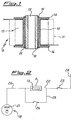
- FIG. 2 shows by way of example an electrical diagram of a single-phase asynchronous motor (18) for control of hydraulic elevators including the device of FIG. 1. It is clear that if the motor (18) were the 3-phase type the electrical diagram would include three devices (8), i.e. one for each phase.
- the device (8) of the present invention is connected by a first wire (20) to the winding (21) of the motor (18) and by another wire (22) to a switch and/or remote controlled switch (23). The latter is connected in turn to the electric power line (24).
- Another wire (25) connected to another switch (26) by-passes the device (8) and connects to the first wire (20) and to the second wire (22) respectively.
- the function of the device (8) in activation of the motor (18) is as follows. Starting of the motor (18) is achieved by closing the switch (23) and holding open the switch (26). In this position of the switches (23,26) the current coming from the power supply line (24) passes from the wire (22) to the device (8), is 'filtered' by said device (8), passes from the wire (22) to the device (8), is 'filtered' by said device (8) and then sent over the wire (20) to the winding (21) of the motor (18) which begins its operational cycle reaching its nominal value.
- the switch (26) Upon achievement of the operational cycle of the motor (18) the switch (26) is closed and the current can also by-pass the device (8) because the voltage now required for powering said motor (18) remains substantially constant, i.e. the conditions in which the undesired current peaks occur no longer exist.
- the device (8) of the present invention can be defined a 'variable filter-reducer of current'.
Landscapes
- Engineering & Computer Science (AREA)
- Power Engineering (AREA)
- Motor And Converter Starters (AREA)
- Control Of Ac Motors In General (AREA)
- Control Of Motors That Do Not Use Commutators (AREA)
- Control Of Electric Motors In General (AREA)
- Control Of Direct Current Motors (AREA)
Abstract
Description
- The present invention relates to a device for reducing current peaks during starting of an asynchronous electric motor.
- More specifically the present invention relates to a device for reducing current peaks during starting of an asynchronous electric motor for control of hydraulic elevators.
- As is known, the movement of passenger and/or freight elevators and the like with hydraulic drive is generally performed by the use of asynchronous electric motors whose starting can be the direct, star-triangle, resistance or electronic type or other equivalent systems.
- Said starting, as is known, causes considerable shortcomings and limitations in said asynchronous motors due to the fact that in case of direct starting the sudden drawing of current from the supply network is in general at least three times as much as normally required during operation of the motor.
- This momentary drawing of current results not only in a possible, early and undesired wear of the mechanical parts of the motor but also formation of the well known current peaks. For this reason the motor is provided in such a manner as to resist a current greater than that required for its normal duty with resulting additional problems of size, connection and others.
- Star-triangle starting of an asynchronous motor is theoretically efficient but the motor is practically subjected to two starts. Indeed, the fluid operating it has a braking action during the exchange phase of the remote controlled switches and or switches so that initially and generally it includes a phase of insufficient power supply.
- For this reason this type of starting, in addition to requiring momentary drain of current twice from the supply network with resulting associated current peaks, operative activation of the motor is quite difficult.
- Resistance starting of an asynchronous motor displays different shortcomings such as for example heating of the resistances, sensitivity of the resistances to voltage differences, possible slightly retarded changeover of the remote controlled switches with resulting burning of the resistances, etc. All of these shortcomings make this type of starting system, overall, unreliable and of relatively short life.
- Lastly, electronic starting of an asynchronous motor requires special and accurate settings by highly skilled personnel. This shortcoming and the overall delicacy of the equipment considerably affect the operating and maintenance costs of the motor.
- From the foregoing it is seen that the principal shortcomings of asynchronous motors originate mainly in the current peaks, which occur during starting of the motors.
- The purpose of the present invention is to provide a device for starting asynchronous electric motors which would not have the above described shortcomings. More specifically, the purpose of the present invention is to provide a device designed to reduce current peaks during starting of asynchronous motors for control of hydraulic elevators.
- In accordance with the present invention these and other purposes are achieved by a device comprising substantially a metal nucleus inserted in a tubular body made of insulating material on which is arranged a copper wire winding connected to the phase of the motor and to a pair of switches and/or remote controlled switches respectively.
- Said winding materializes an inductance which maintains a value essentially less than the current taken from the electric power network during starting of the motor and this is based on well known physical laws (Faraday-Newman-Leinz) and in relation to the structural conformation of said inductance.
- In accordance with another characteristic of the present invention the winding or inductance of the device is immersed in and cooled by the same operating fluid as the motor.
- Preferably the opposite ends of the tubular body are structurally formed in such a manner as to form a flange for containing the winding.
- In addition the metal nucleus is preferably traversed longitudinally by a passage which lightens its weight and can be positioned stably in the tubular body by Seger cones or equivalent means.
- In accordance with another characteristic of the device in accordance with the present invention the inductance can be provided by winding on the tubular body the same wire coming from the motor winding.
- The characteristics and advantages of the device of the present invention can be better understood from the following detailed description in which reference is made to the annexed drawings representing a preferred but nonlimiting form of embodiment of the present invention and wherein:
- FIG. 1 is a schematic longitudinal cross section view of the device of the present invention, and
- FIG. 2 shows an electrical diagram of a single-phase asynchronous motor for control of hydraulic traction elevators including the device of FIG. 1.
- With reference to FIG. 1 the device (8) of the present invention comprises essentially a metal nucleus (10) inserted in a tubular body (12) made of insulating material, e.g. plastic, and bounded at its opposite ends by flanges (14,16).
- On said tubular body (12) is a winding (13) consisting of copper wires positioned stably by the flanges (14,16). Said winding (13) materializes an inductance connected to the winding of the motor and to a pair of switches and/or remote controlled switches as specified below.
- The winding or inductance (13) is preferably immersed in and cooled by the operating fluid of the motor which, in FIG. 1, is shown schematically in broken lines as a rectangle (11).
- The winding or inductance (13) can be provided by winding around the tubular body (12) the same wire coming from the motor winding.
- The metal nucleus (10) is stably positioned in the tubular body (12) by Seger cones (15) or equivalent means and traversed by a longitudinal passage (17) which reduces in this manner the total weight of the device (8).
- It has been noted with surprise that the device (8) provided in accordance with the present invention as described above is capable of eliminating or reducing considerably the known current peaks during starting of an asynchronous motor for control of hydraulic-traction elevators because it holds substantially always constant the supply voltage of the motor on the basis of known physical laws (Faraday-Newman-Leinz). In practice, the device (8) of the present invention causes an initial drop in voltage and hence in current by inductance instead of resistances. This voltage drop in the starting phase of the motor (18) can have a preset value in relation to the structural conformation of the winding (13).
- FIG. 2 shows by way of example an electrical diagram of a single-phase asynchronous motor (18) for control of hydraulic elevators including the device of FIG. 1. It is clear that if the motor (18) were the 3-phase type the electrical diagram would include three devices (8), i.e. one for each phase.
- In said FIG. 2 the device (8) of the present invention is connected by a first wire (20) to the winding (21) of the motor (18) and by another wire (22) to a switch and/or remote controlled switch (23). The latter is connected in turn to the electric power line (24).
- Another wire (25) connected to another switch (26) by-passes the device (8) and connects to the first wire (20) and to the second wire (22) respectively.
- The function of the device (8) in activation of the motor (18) is as follows. Starting of the motor (18) is achieved by closing the switch (23) and holding open the switch (26). In this position of the switches (23,26) the current coming from the power supply line (24) passes from the wire (22) to the device (8), is 'filtered' by said device (8), passes from the wire (22) to the device (8), is 'filtered' by said device (8) and then sent over the wire (20) to the winding (21) of the motor (18) which begins its operational cycle reaching its nominal value.
- Upon achievement of the operational cycle of the motor (18) the switch (26) is closed and the current can also by-pass the device (8) because the voltage now required for powering said motor (18) remains substantially constant, i.e. the conditions in which the undesired current peaks occur no longer exist.
- In practice the device (8) of the present invention can be defined a 'variable filter-reducer of current'.
- From the foregoing the advantages as well as the useful effects of the device of the present invention are evident. Thus for example the device of the present invention:
- prevents or considerably reduces current peaks upon starting of the motor,
- allows longer life of the mechanical and electrical parts of the motor, and
- holds overheating of the motor within normal values and the current peaks cannot be effected.
- Although the invention has been described in conjunction with specific embodiments it is evident that many alternatives and variations will be apparent to those skilled in the art in light of the foregoing description. Accordingly, the invention is intended to embrace all of the alternatives and variations that fall within the spirit and scope of the appended claims.
Claims (10)
- Device designed to reduce current peaks during starting of an asynchronous motor (18) for control of hydraulic elevators associated therewith characterized in that it comprises a metal nucleus (10) inserted in a tubular body (12) of insulating material on which is arranged a winding (13) of copper wire to materialize an inductance, said winding (13) being connected either to the winding (21) of the motor (18) or to the electrical power supply network (24).
- Device in accordance with claim 1 characterized in that the winding (13) is immersed in and cooled by the fluid (11) operating in the motor (18).
- Device in accordance with claim 1 or claim 2 characterized in that the tubular body (12) is bounded on opposite ends by flanges (14,16) which hold the winding (13) stably positioned.
- Device in accordance with any one of the above claims characterized in that the metal nucleus (10) is traversed longitudinally by a passage (17).
- Device in accordance with any one of the above claims characterized in that the metal nucleus (10) is positioned stably in the tubular body (12) by Seger cones (15).
- Device in accordance with any one of the above claims characterized in that the winding (13) is achieved by winding around the tubular body (12) the same wire (20) coming from the winding (21) of the motor (18).
- Device in accordance with any one of the above claims characterized in that the winding (13) is connected to the winding (21) of the motor by a first wire (20) and to the electrical power supply network (24) by a second wire (22), said first and second wires (20,22) being also connected directly together by another wire (25) provided with a switch (26).
- Device in accordance with any one of the above claims characterized in that the value of the voltage drop during the starting phase of the motor (18) is in relation to the structural conformation of the winding (13).
- Device in accordance with any one of the above claims characterized in that it fulfills a 'variable filter-reducer of current' function of the current coming from the electrical power supply network (24).
- Device in accordance with any one of the above claims characterized in that it is associated with each phase of an asynchronous motor (18) for control of hydraulic elevators.
Applications Claiming Priority (2)
| Application Number | Priority Date | Filing Date | Title |
|---|---|---|---|
| ITMI910746A IT1245557B (en) | 1991-03-20 | 1991-03-20 | DEVICE SUITABLE TO REDUCE THE "PEAKS" OF THE CURRENT IN THE STARTING OF AN ASYNCHRONOUS ELECTRIC MOTOR FOR THE CONTROL OF HYDRAULIC LIFTS |
| ITMI910746 | 1991-03-20 |
Publications (2)
| Publication Number | Publication Date |
|---|---|
| EP0504610A1 true EP0504610A1 (en) | 1992-09-23 |
| EP0504610B1 EP0504610B1 (en) | 1997-05-14 |
Family
ID=11359140
Family Applications (1)
| Application Number | Title | Priority Date | Filing Date |
|---|---|---|---|
| EP92102901A Expired - Lifetime EP0504610B1 (en) | 1991-03-20 | 1992-02-21 | Device for reducing current peaks during starting of an asynchronous motor |
Country Status (6)
| Country | Link |
|---|---|
| EP (1) | EP0504610B1 (en) |
| AT (1) | ATE153195T1 (en) |
| DE (1) | DE69219653T2 (en) |
| ES (1) | ES2100968T3 (en) |
| GR (1) | GR3023478T3 (en) |
| IT (1) | IT1245557B (en) |
Cited By (1)
| Publication number | Priority date | Publication date | Assignee | Title |
|---|---|---|---|---|
| EP0797224A1 (en) * | 1996-03-22 | 1997-09-24 | Siemens Aktiengesellschaft | Choke coil for an intermediate circuit short-circuit device |
Citations (5)
| Publication number | Priority date | Publication date | Assignee | Title |
|---|---|---|---|---|
| US2913640A (en) * | 1957-03-20 | 1959-11-17 | Gen Dynamics Corp | Electromagnetic coil assembly |
| DE1763807A1 (en) * | 1968-08-14 | 1971-12-09 | Siemens Ag | Process for the production of chokes, in particular smoothing chokes |
| FR2176761A1 (en) * | 1972-03-17 | 1973-11-02 | Siemens Ag | |
| GB2157087A (en) * | 1984-03-13 | 1985-10-16 | Weyrad | Improvements relating to linearity coils |
| FR2608332A1 (en) * | 1986-12-13 | 1988-06-17 | Grundfos Int | ELECTRIC MOTOR WITH FREQUENCY CONVERTER FOR ADJUSTING ENGINE OPERATING PARAMETERS |
-
1991
- 1991-03-20 IT ITMI910746A patent/IT1245557B/en active IP Right Grant
-
1992
- 1992-02-21 AT AT92102901T patent/ATE153195T1/en not_active IP Right Cessation
- 1992-02-21 DE DE69219653T patent/DE69219653T2/en not_active Expired - Fee Related
- 1992-02-21 EP EP92102901A patent/EP0504610B1/en not_active Expired - Lifetime
- 1992-02-21 ES ES92102901T patent/ES2100968T3/en not_active Expired - Lifetime
-
1997
- 1997-05-19 GR GR970401127T patent/GR3023478T3/en unknown
Patent Citations (5)
| Publication number | Priority date | Publication date | Assignee | Title |
|---|---|---|---|---|
| US2913640A (en) * | 1957-03-20 | 1959-11-17 | Gen Dynamics Corp | Electromagnetic coil assembly |
| DE1763807A1 (en) * | 1968-08-14 | 1971-12-09 | Siemens Ag | Process for the production of chokes, in particular smoothing chokes |
| FR2176761A1 (en) * | 1972-03-17 | 1973-11-02 | Siemens Ag | |
| GB2157087A (en) * | 1984-03-13 | 1985-10-16 | Weyrad | Improvements relating to linearity coils |
| FR2608332A1 (en) * | 1986-12-13 | 1988-06-17 | Grundfos Int | ELECTRIC MOTOR WITH FREQUENCY CONVERTER FOR ADJUSTING ENGINE OPERATING PARAMETERS |
Non-Patent Citations (2)
| Title |
|---|
| IEEE TRANSACTIONS ON INDUSTRY APPLICATIONS. vol. IA-20, no. 1, January 1984, NEW YORK US pages 46 - 55; F.M.BRUCE ET AL.: 'Reduced-voltage starting of squirrel-cage induction motors' * |
| PATENT ABSTRACTS OF JAPAN vol. 8, no. 167 (E-258)(1604) 2 August 1984 & JP-A-59 063 960 ( MATSUSHITA ) 11 April 1984 * |
Cited By (1)
| Publication number | Priority date | Publication date | Assignee | Title |
|---|---|---|---|---|
| EP0797224A1 (en) * | 1996-03-22 | 1997-09-24 | Siemens Aktiengesellschaft | Choke coil for an intermediate circuit short-circuit device |
Also Published As
| Publication number | Publication date |
|---|---|
| ITMI910746A1 (en) | 1992-09-20 |
| DE69219653T2 (en) | 1997-09-04 |
| GR3023478T3 (en) | 1997-08-29 |
| ES2100968T3 (en) | 1997-07-01 |
| DE69219653D1 (en) | 1997-06-19 |
| IT1245557B (en) | 1994-09-29 |
| EP0504610B1 (en) | 1997-05-14 |
| ATE153195T1 (en) | 1997-05-15 |
| ITMI910746A0 (en) | 1991-03-20 |
Similar Documents
| Publication | Publication Date | Title |
|---|---|---|
| DE69827108T2 (en) | CIRCUIT BREAKER WITH PIC (COLD LEADER) ELEMENTS | |
| DE19739780B4 (en) | Three-phase motor | |
| EP1683262B1 (en) | Braking method for a synchronous machine | |
| EP0504610A1 (en) | Device for reducing current peaks during starting of an asynchronous motor | |
| DE19535211A1 (en) | Regulation circuit for electromagnetic switchgear drive | |
| DE4220122A1 (en) | Control circuit for DC-operated brakes of pole-changing three-phase motors | |
| JP2005094930A5 (en) | ||
| DE202010015424U1 (en) | Electrical plug-in device with extended functionality | |
| DE2901892A1 (en) | POWER SUPPLY DEVICE FOR A SUPRAL-CONDUCTING MAGNETIC COIL | |
| DE2115998C3 (en) | Arrangement for switching between driving and electrical resistance braking of a direct current series motor | |
| US2233169A (en) | Control system | |
| DE102008049566A1 (en) | Circuit-breaker i.e. opened low voltage circuit-breaker, operating method, involves cooling component of circuit-breaker with blower, which is actuated with electrical energy, where energy provides power that flows over line | |
| EP1573877A1 (en) | Protective switch | |
| US3130328A (en) | Safety device for dual voltage circuits | |
| US911013A (en) | Motor-control system. | |
| DE562038C (en) | Device for starting a single-phase induction motor with the aid of a double coil relay | |
| US1421157A (en) | Control system and apparatus | |
| US2851649A (en) | Parking control for windshield wipers | |
| DE469742C (en) | Automatic on and off switch to protect multi-phase AC lines in the event of asymmetrical loads | |
| CN2190364Y (en) | Protector for open-phase | |
| US1939720A (en) | Automatic system of motor control | |
| US1764420A (en) | Control apparatus | |
| DE3445061C2 (en) | ||
| DE3410600A1 (en) | Protection system: electric motors, cable protection, protection against electrical fire | |
| DE1289172B (en) | Arrangement to protect electrical consumers against excess temperatures |
Legal Events
| Date | Code | Title | Description |
|---|---|---|---|
| PUAI | Public reference made under article 153(3) epc to a published international application that has entered the european phase |
Free format text: ORIGINAL CODE: 0009012 |
|
| AK | Designated contracting states |
Kind code of ref document: A1 Designated state(s): AT BE CH DE DK ES FR GB GR LI LU NL PT SE |
|
| DX | Miscellaneous (deleted) | ||
| 17P | Request for examination filed |
Effective date: 19930302 |
|
| 17Q | First examination report despatched |
Effective date: 19941103 |
|
| GRAG | Despatch of communication of intention to grant |
Free format text: ORIGINAL CODE: EPIDOS AGRA |
|
| GRAH | Despatch of communication of intention to grant a patent |
Free format text: ORIGINAL CODE: EPIDOS IGRA |
|
| GRAH | Despatch of communication of intention to grant a patent |
Free format text: ORIGINAL CODE: EPIDOS IGRA |
|
| GRAA | (expected) grant |
Free format text: ORIGINAL CODE: 0009210 |
|
| AK | Designated contracting states |
Kind code of ref document: B1 Designated state(s): AT BE CH DE DK ES FR GB GR LI LU NL PT SE |
|
| PG25 | Lapsed in a contracting state [announced via postgrant information from national office to epo] |
Ref country code: DK Effective date: 19970514 |
|
| REF | Corresponds to: |
Ref document number: 153195 Country of ref document: AT Date of ref document: 19970515 Kind code of ref document: T |
|
| REG | Reference to a national code |
Ref country code: CH Ref legal event code: NV Representative=s name: TROESCH SCHEIDEGGER WERNER AG Ref country code: CH Ref legal event code: EP |
|
| REF | Corresponds to: |
Ref document number: 69219653 Country of ref document: DE Date of ref document: 19970619 |
|
| REG | Reference to a national code |
Ref country code: ES Ref legal event code: FG2A Ref document number: 2100968 Country of ref document: ES Kind code of ref document: T3 |
|
| ET | Fr: translation filed | ||
| REG | Reference to a national code |
Ref country code: GR Ref legal event code: FG4A Free format text: 3023478 |
|
| PG25 | Lapsed in a contracting state [announced via postgrant information from national office to epo] |
Ref country code: LU Free format text: LAPSE BECAUSE OF NON-PAYMENT OF DUE FEES Effective date: 19980221 |
|
| PLBE | No opposition filed within time limit |
Free format text: ORIGINAL CODE: 0009261 |
|
| STAA | Information on the status of an ep patent application or granted ep patent |
Free format text: STATUS: NO OPPOSITION FILED WITHIN TIME LIMIT |
|
| 26N | No opposition filed | ||
| REG | Reference to a national code |
Ref country code: GB Ref legal event code: IF02 |
|
| PGFP | Annual fee paid to national office [announced via postgrant information from national office to epo] |
Ref country code: GB Payment date: 20040109 Year of fee payment: 13 |
|
| PGFP | Annual fee paid to national office [announced via postgrant information from national office to epo] |
Ref country code: BE Payment date: 20040112 Year of fee payment: 13 |
|
| PGFP | Annual fee paid to national office [announced via postgrant information from national office to epo] |
Ref country code: FR Payment date: 20040123 Year of fee payment: 13 |
|
| PGFP | Annual fee paid to national office [announced via postgrant information from national office to epo] |
Ref country code: SE Payment date: 20040130 Year of fee payment: 13 |
|
| PGFP | Annual fee paid to national office [announced via postgrant information from national office to epo] |
Ref country code: ES Payment date: 20040224 Year of fee payment: 13 |
|
| PGFP | Annual fee paid to national office [announced via postgrant information from national office to epo] |
Ref country code: AT Payment date: 20040226 Year of fee payment: 13 |
|
| PGFP | Annual fee paid to national office [announced via postgrant information from national office to epo] |
Ref country code: PT Payment date: 20040227 Year of fee payment: 13 Ref country code: NL Payment date: 20040227 Year of fee payment: 13 Ref country code: GR Payment date: 20040227 Year of fee payment: 13 |
|
| PGFP | Annual fee paid to national office [announced via postgrant information from national office to epo] |
Ref country code: CH Payment date: 20040427 Year of fee payment: 13 |
|
| PGFP | Annual fee paid to national office [announced via postgrant information from national office to epo] |
Ref country code: DE Payment date: 20040430 Year of fee payment: 13 |
|
| PG25 | Lapsed in a contracting state [announced via postgrant information from national office to epo] |
Ref country code: GB Free format text: LAPSE BECAUSE OF NON-PAYMENT OF DUE FEES Effective date: 20050221 Ref country code: AT Free format text: LAPSE BECAUSE OF NON-PAYMENT OF DUE FEES Effective date: 20050221 |
|
| PG25 | Lapsed in a contracting state [announced via postgrant information from national office to epo] |
Ref country code: SE Free format text: LAPSE BECAUSE OF NON-PAYMENT OF DUE FEES Effective date: 20050222 Ref country code: ES Free format text: LAPSE BECAUSE OF NON-PAYMENT OF DUE FEES Effective date: 20050222 |
|
| PG25 | Lapsed in a contracting state [announced via postgrant information from national office to epo] |
Ref country code: LI Free format text: LAPSE BECAUSE OF NON-PAYMENT OF DUE FEES Effective date: 20050228 Ref country code: CH Free format text: LAPSE BECAUSE OF NON-PAYMENT OF DUE FEES Effective date: 20050228 Ref country code: BE Free format text: LAPSE BECAUSE OF NON-PAYMENT OF DUE FEES Effective date: 20050228 |
|
| PG25 | Lapsed in a contracting state [announced via postgrant information from national office to epo] |
Ref country code: PT Free format text: LAPSE BECAUSE OF NON-PAYMENT OF DUE FEES Effective date: 20050822 |
|
| BERE | Be: lapsed |
Owner name: *GMV MARTINI S.P.A. Effective date: 20050228 |
|
| PG25 | Lapsed in a contracting state [announced via postgrant information from national office to epo] |
Ref country code: NL Free format text: LAPSE BECAUSE OF NON-PAYMENT OF DUE FEES Effective date: 20050901 Ref country code: DE Free format text: LAPSE BECAUSE OF NON-PAYMENT OF DUE FEES Effective date: 20050901 |
|
| PG25 | Lapsed in a contracting state [announced via postgrant information from national office to epo] |
Ref country code: GR Free format text: LAPSE BECAUSE OF NON-PAYMENT OF DUE FEES Effective date: 20050905 |
|
| EUG | Se: european patent has lapsed | ||
| GBPC | Gb: european patent ceased through non-payment of renewal fee |
Effective date: 20050219 |
|
| REG | Reference to a national code |
Ref country code: CH Ref legal event code: PL |
|
| PG25 | Lapsed in a contracting state [announced via postgrant information from national office to epo] |
Ref country code: FR Free format text: LAPSE BECAUSE OF NON-PAYMENT OF DUE FEES Effective date: 20051031 |
|
| REG | Reference to a national code |
Ref country code: PT Ref legal event code: MM4A Effective date: 20050822 |
|
| NLV4 | Nl: lapsed or anulled due to non-payment of the annual fee |
Effective date: 20050901 |
|
| REG | Reference to a national code |
Ref country code: FR Ref legal event code: ST Effective date: 20051031 |
|
| REG | Reference to a national code |
Ref country code: ES Ref legal event code: FD2A Effective date: 20050222 |
|
| BERE | Be: lapsed |
Owner name: *GMV MARTINI S.P.A. Effective date: 20050228 |