EP0504213B1 - Verbesserte klebstoffspender - Google Patents
Verbesserte klebstoffspender Download PDFInfo
- Publication number
- EP0504213B1 EP0504213B1 EP91900278A EP91900278A EP0504213B1 EP 0504213 B1 EP0504213 B1 EP 0504213B1 EP 91900278 A EP91900278 A EP 91900278A EP 91900278 A EP91900278 A EP 91900278A EP 0504213 B1 EP0504213 B1 EP 0504213B1
- Authority
- EP
- European Patent Office
- Prior art keywords
- cap
- barrel
- pin
- pipette
- nozzle
- Prior art date
- Legal status (The legal status is an assumption and is not a legal conclusion. Google has not performed a legal analysis and makes no representation as to the accuracy of the status listed.)
- Expired - Lifetime
Links
- 239000000853 adhesive Substances 0.000 title claims abstract description 44
- 230000001070 adhesive effect Effects 0.000 title claims abstract description 44
- 230000000149 penetrating effect Effects 0.000 claims abstract description 4
- 230000004888 barrier function Effects 0.000 claims description 12
- 230000002093 peripheral effect Effects 0.000 claims description 9
- 230000000295 complement effect Effects 0.000 claims 1
- 230000001681 protective effect Effects 0.000 abstract description 4
- 239000004033 plastic Substances 0.000 description 3
- 229920003023 plastic Polymers 0.000 description 3
- 238000010276 construction Methods 0.000 description 2
- 239000000463 material Substances 0.000 description 2
- 101000793686 Homo sapiens Azurocidin Proteins 0.000 description 1
- 239000004830 Super Glue Substances 0.000 description 1
- 230000000994 depressogenic effect Effects 0.000 description 1
- FGBJXOREULPLGL-UHFFFAOYSA-N ethyl cyanoacrylate Chemical compound CCOC(=O)C(=C)C#N FGBJXOREULPLGL-UHFFFAOYSA-N 0.000 description 1
- 239000003292 glue Substances 0.000 description 1
- 239000002184 metal Substances 0.000 description 1
- 239000004810 polytetrafluoroethylene Substances 0.000 description 1
- 229920001343 polytetrafluoroethylene Polymers 0.000 description 1
- 230000000284 resting effect Effects 0.000 description 1
- 238000007789 sealing Methods 0.000 description 1
- 229910001220 stainless steel Inorganic materials 0.000 description 1
- 239000010935 stainless steel Substances 0.000 description 1
Images


Classifications
-
- B—PERFORMING OPERATIONS; TRANSPORTING
- B43—WRITING OR DRAWING IMPLEMENTS; BUREAU ACCESSORIES
- B43M—BUREAU ACCESSORIES NOT OTHERWISE PROVIDED FOR
- B43M11/00—Hand or desk devices of the office or personal type for applying liquid, other than ink, by contact to surfaces, e.g. for applying adhesive
- B43M11/06—Hand-held devices
- B43M11/08—Hand-held devices of the fountain-pen type
-
- B—PERFORMING OPERATIONS; TRANSPORTING
- B65—CONVEYING; PACKING; STORING; HANDLING THIN OR FILAMENTARY MATERIAL
- B65D—CONTAINERS FOR STORAGE OR TRANSPORT OF ARTICLES OR MATERIALS, e.g. BAGS, BARRELS, BOTTLES, BOXES, CANS, CARTONS, CRATES, DRUMS, JARS, TANKS, HOPPERS, FORWARDING CONTAINERS; ACCESSORIES, CLOSURES, OR FITTINGS THEREFOR; PACKAGING ELEMENTS; PACKAGES
- B65D50/00—Closures with means for discouraging unauthorised opening or removal thereof, with or without indicating means, e.g. child-proof closures
- B65D50/02—Closures with means for discouraging unauthorised opening or removal thereof, with or without indicating means, e.g. child-proof closures openable or removable by the combination of plural actions
- B65D50/04—Closures with means for discouraging unauthorised opening or removal thereof, with or without indicating means, e.g. child-proof closures openable or removable by the combination of plural actions requiring the combination of simultaneous actions, e.g. depressing and turning, lifting and turning, maintaining a part and turning another one
- B65D50/045—Closures with means for discouraging unauthorised opening or removal thereof, with or without indicating means, e.g. child-proof closures openable or removable by the combination of plural actions requiring the combination of simultaneous actions, e.g. depressing and turning, lifting and turning, maintaining a part and turning another one where one action elastically deforms or deflects at least part of the closure, the container or an intermediate element, e.g. a ring
- B65D50/046—Closures with means for discouraging unauthorised opening or removal thereof, with or without indicating means, e.g. child-proof closures openable or removable by the combination of plural actions requiring the combination of simultaneous actions, e.g. depressing and turning, lifting and turning, maintaining a part and turning another one where one action elastically deforms or deflects at least part of the closure, the container or an intermediate element, e.g. a ring and such deformation causes the disengagement of locking means, e.g. the release of a pawl-like element from a tooth or abutment, to allow removal of the closure by simultaneous rotation
Definitions
- THE PRESENT INVENTION relates to adhesive dispensers.
- a known adhesive dispenser for dispensing cyano-acrylate adhesive comprises a dispenser barrel containing a deformable pipette charged with the adhesive to be dispensed.
- the pipette extends axially within the barrel of the dispenser with a nozzle of the pipette projecting through an end wall of the barrel at one end of the barrel.
- a pair of dispensing buttons project through opposed holes formed in the side wall of the barrel and, in use, the adhesive is dispensed from the pipette by gently squeezing the dispensing buttons. The action of squeezing the buttons compresses the pipette within the barrel and forces adhesive out of an outlet passage in the pipette nozzle.
- the known dispenser comprises a protective push-fit cap which is attached to the one end of the barrel to enclose the projecting pipette nozzle when the dispenser is not in use.
- the dispenser is supplied with the outlet passage in the pipette of the nozzle in a closed condition and, when the dispenser is used, the cap is removed and the pipette nozzle is pierced with a standard pin to open the outlet passage for the adhesive.
- adhesive often escapes from the pipette under pressure. This can result in dangerous adhesive getting onto the hands or clothes of a user.
- the push-fit cap of the known dispenser is also readily removed simply by pulling the cap and barrel apart and thus represents a hazard if the dispenser should fall into the hands of a small child.
- the present invention aims to overcome, or at least mitigate, the above disadvantages of the known dispenser.
- an adhesive dispenser comprising: a barrel which houses a deformable pipette charged with adhesive and having a nozzle projecting from one end of the barrel; dispensing means carried by the barrel for compressing the pipette to dispense adhesive through an outlet passage in the pipette nozzle; a cap for attachment to the one end of the barrel to enclose the projecting pipette nozzle; and pin means carried by the cap for penetrating the outlet passage of the pipette nozzle when the cap is attached to the barrel, characterised in that an internal barrier in the outlet passage of the pipette nozzle closes the outlet passage until the cap is attached to the barrel and is so located in the outlet passage that it is pierced only by a tip of the pin means.
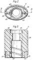
- an adhesive dispenser 1 embodying the present invention comprises a hollow rigid barrel 2 containing a deformable pipette (not shown) having a nozzle 3 ( Figure 6) projecting from one end of the barrel.
- a protective cap 4 of plastics material is attached to the one end of the barrel to enclose the nozzle 3 of the deformable pipette.
- a locking sleeve 5 mounted on the one end of the barrel 2 enables the cap 4 to be securely locked to the barrel 2 when the dispenser is not in use.
- the hollow barrel 2 has a substantially oval cross-section.
- Apertures 6 are formed in the opposing major longitudinal surface regions of the barrel 2 and dispensing buttons 7, having a diameter slightly less than that of the apertures 7, are biased apart to project through the apertures 6.
- the dispensing buttons 7 have enlarged actuating portions (not shown) disposed within the barrel 1 for engaging and compressing the charged pipette when the buttons are pressed inwardly of the barrel 2.
- a pair of arcuate projections 8 are formed on the barrel above and below each dispensing button 7.
- the minor longitudinal surface regions of the barrel 2 are formed with a pair of opposed locking windows 9 spaced from an end wall 10 of the barrel at the one end of the barrel.
- a central hollow mounting boss 11 projects axially from the end wall 10 of the barrel 2 and has a cylindrical portion 12 formed with an external screw thread.
- the end wall 10 is formed with an arcuate aperture 19 circumferentially aligned with a respective one of the locking windows 9 in the side wall of the barrel 2.
- an end portion of the mounting boss 11 is formed as a block 23.
- the deformable pipette (not shown) charged with adhesive extends axially in the barrel 1 with the nozzle 3 of the pipette projecting out of the barrel through the mounting boss 11 of the end wall 10.
- the pipette nozzle 3 has an adhesive outlet passage 26 formed with an internal barrier 27 which closes the passage 26 until pierced.
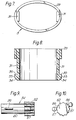
- the locking sleeve 5 of the dispenser is shown in more detail in Figures 7 and 8.
- This locking sleeve comprises an oval collar 29 which carries a pair of locking legs 31 depending from the inside surface of the collar 29 at opposite ends of the major axis of the collar.
- the free end of each locking leg 31 is formed with an outwardly directed lug 33.
- a lower surface of each lug 33 is chamfered to form a ramp surface 34 and the upper surface of each lug 33 extends radially to form an abutment surface 35.
- the locking legs 31 are dimensioned to pass into the barrel 1 through the arcuate apertures 19 in the end wall 10 of the barrel when the collar 29 is fitted onto the one end of the barrel as shown in Figure 1 and the lugs 33 are dimensioned to project through the locking windows 9 when axially aligned therewith, as shown in Figure 11.
- the protective cap 4 of the dispenser is generally oval in cross-section to match the dispenser barrel 2 and comprises an end wall 38 with a depending peripheral wall 39 terminating in a skirt 43 of reduced thickness.
- a slit 41 formed in the peripheral wall 39 extends axially towards the end wall from the lower edge of the skirt 43 and is disposed at one end of the minor axis of the oval cross-section of the peripheral wall.
- the skirt 43 is also formed with two further axially extending slits 47 located at respective ends of the major axis of the oval cross-section of the skirt 43. The two slits 47 are positioned above the apertures 19 in the end wall 10 of the barrel 2 when the cap 4 is in place on the barrel 2.
- a cylindrical mounting socket 49 depends centrally within the cap 4 and is provided with an internal screw thread adapted to be engaged with the external screw thread on the mounting boss 11 of the barrel 2 to attach the cap 4 to the barrel 2.
- the mounting socket 49 is also provided with an axially extending slit 50 aligned with the slit 41 in the peripheral wall 39 of the cap 4.
- Two latching arms 53 extend axially within the cap 37 on opposite sides of the mounting skirt 49 between the mounting skirt and the slits 47 in the skirt 45.
- the latching arms 53 are adapted to engage in nip of the clips 13 provided on the end wall 10 of the barrel 2 when the cap 4 is attached to the barrel.
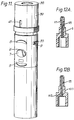
- the pin unit 54 is mounted centrally in the cap 4 concentrically within the mounting skirt 49, so as to be aligned with the nozzle 3 of the pipette projecting through the boss 11 when the cap 4 is applied to the barrel 2.
- the pin unit 54 comprises a longitudinally ribbed mounting body 52 which is made of plastics material and is received in a mounting bore 55 ( Figure 3) of the cap 4, which mounting body 52 carries on stalks 56 two locating pegs 57 which are received in corresponding bores 58 ( Figure 4) in the cap 4 when the body 52 is received in bore 55.
- a metal pin 59 extends from the mounting body and is enclosed by a shroud 60 formed with an axial slit 61 which is aligned with the slits 41, 50 in the peripheral wall 39 and mounting socket 49 of the cap 4 when the pin unit 54 is installed in the cap.
- the pin 59 has a length such that, when the cap 4 is in place on the barrel 2, the pin 59 extends into the outlet passage 26 in the pipette nozzle 3 beyond the barrier 27, with the pin shroud 60 enclosing the nozzle 3.
- the locking legs 31 of the locking sleeve are inserted into the respective apertures 19 in the end wall 10 of the barrel 2.
- the collar 29 is then pushed downwardly until the lugs 33 project through the windows 9 in the barrel 2.
- Continued downward pressure on the collar 29 depresses the lugs 33 inwardly as a result of the ramp surfaces 34 of the lugs to enable the legs to be inserted further into the barrel until the collar 29 which is an inoperative position resting on the end wall 10 of the barrel 2.
- the cap 4 is then applied to the barrel 2 and the action of screwing the mounting socket 49 onto the mounting boss 11 of the barrel 2 drives the pin 59 into the outlet passage 26 of the pipette nozzle 3.
- the correct engagement can be checked through the slits 41, 50 and 61 in the peripheral wall 39, mounting socket 49 and shroud 60.
- the pin 59 is forced through the internal barrier 27 in the outlet passage 26 of the pipette nozzle 3, thus opening the passage for adhesive when the pin 59 is subsequently removed with the cap 4.
- the slit 61 in the shroud 60 allows flexing of the shroud when removing the cap 4 and thus prevents the shroud from sticking to the pipette nozzle 3 when the cap 4 is left in place on the barrel 2.
- the latching arms 53 are engaged in the clips 13 on the end wall 10 of the barrel and the slits 47 are aligned with the apertures 19 in the end wall 10 of the barrel 2.
- the collar 29 can then be raised from its inoperative position ( Figure 1) into an operative locking position in which the lugs 33 project through the windows 9 in the barrel 2 and the collar 29 encloses the skirt 43 of the peripheral wall 39 of the cap.
- the abutment surface 35 of the lugs 33 then ensures that the lugs 33 are secured in the windows 9 against further upward movement.
- the upper end of the legs 31 of the locking sleeve 5 engage in the slots 47 in the skirt 43 of the cap 4 and thereby prevent the cap from being rotated and thus removed until the lugs 33 are depressed and the collar 29 is moved downwardly into its inoperative position.
- the pin unit 54 Should become stuck to the pipette nozzle 3, the application of a torque exceeding a predetermined value when removing the cap 4 will cause the frangible connections between the mounting pins 57 and the mounting body to shear, thereby separating the pin means from the cap and allowing the rest of the cap to be unscrewed without damaging the pipette nozzle. The pin unit can then be gently prised of the nozzle and continue to be used as a separate unit from the cap.
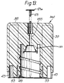
- Figure 12A is an axial cross-sectional view through the nozzle 3 of the deformable pipette of the adhesive dispenser 1 of Figures 1 to 11, but with the piercable internal barrier 27 near the tip of the nozzle. It has been found, however, that with an internal barrier 27 at this location the pin 59 penetrated a long way past the barrier upon sealing the dispenser after use. As a consequence glue may tend to accumulate around the pin 59 and make it difficult to withdraw the pin after some time. Further, under some circumstances the withdrawal of the pin 59 may leave a residual quantity of gelled adhesive below the barrier 27, thereby clogging the nozzle.
- the nozzle 123 according to the present invention and illustrated in Figure 12B is intended to overcome this problem by the repositioning of the internal barrier 127 near the base of the nozzle, which means that the tip of the pin 59 only just pierces the barrier and insufficient of th epin protrudes past the barrier to accumulate adhesive.
- Figure 13 illustrates a modified cap construction 104 for the adhesive dispenser 1, in which a pin shroud 160 is formed integrally with the rest of the cap 104 and a PTFE-coated stainless steel pin 159 is forced into the cap from above into the position shown in dashed lines in Figure 13 so as to extend through the bore 155 and the shroud 160 into the interior of the cap.
- the pin 159 has a flattened oval head 159a which has a major dimension greater than the diameter of the enlarged portion 155a of bore 55 into which it is driven, so that the head bites into the plastic of the cap 104 to prevent the pin 159 being pushed out or rotating so as reliably to enable the torque to be applied to the cap to separate the pin from the nozzle 23 or 123.
Landscapes
- Engineering & Computer Science (AREA)
- Mechanical Engineering (AREA)
- Coating Apparatus (AREA)
- Adhesives Or Adhesive Processes (AREA)
- Processes Of Treating Macromolecular Substances (AREA)
- Closures For Containers (AREA)
- Feeding, Discharge, Calcimining, Fusing, And Gas-Generation Devices (AREA)
Claims (10)
- Klebstoffspender mit einer zylinderförmigen Hülse (2), die eine verformbare Pipette umgibt, die mit Klebstoff gefüllt ist und eine Austrittsdüse (3) aufweist, die aus einem Ende der zylinderförmigen Hülse herausragt; mit Abgabemitteln (7) auf der zylinderförmigen Hülse (2) zum Zusammendrücken der Pipette zum Ausdrücken des Klebstoffes durch einen Auslaßöffnung (26) in der Austrittsdüse (3) der Pipette; mit einer Schutzkappe (4) zur Befestigung an einem Ende der zylinderförmigen Hülse (2) zum Verschließen der herausragenden Austrittsdüse (3) der Pipette; und mit von der Schutzkappe getragenen Dornelementen (54) zum Durchdringen der Auslaßöffnung (26) der Austrittsdüse (3) der Pipette, wenn die Schutzkappe (4) auf die zylinderförmige Hülse (2) aufgesteckt ist, dadurch gekennzeichnet,
daß eine innere Schutzwand (127) in der Auslaßöffnung (26) der Austrittsdüse (3) der Pipette die Auslaßöffnung (26) verschließt, bis die Schutzkappe (4) auf die zylinderförmige Hülse (2) aufgesteckt wird und in der Auslaßöffnung (26) derart angeordnet ist, daß sie nur von einer Spitze der Dornmittel (54) durchbohrt wird. - Klebstoffspender nach Anspruch 1,
dadurch gekennzeichnet,
daß die Dornmittel (54) einen Dorn (59) zum Durchdringen der Austrittsöffnung (26) der Auslaßdüse (3) der Pipette und eine Dornummantelung (60) aufweisen, die den Dorn (59) umgibt und über der Auslaßdüse (3) der Pipette anliegt, wenn die Schutzkappe (4) auf die zylinderförmige Hülse (2) aufgesteckt ist. - Klebstoffspender nach Anspruch 2,
dadurch gekennzeichnet,
daß die Ummantelung (60) einen schlitzförmigen Spalt (61) aufweist, der eine Biegung der Ummantelung (60) erlaubt, um ein Ankleben der Ummantelung (60) an der Austrittsdüse (3) der Pipette zu vermeiden. - Klebstoffspender nach einem der vorhergehenden Ansprüche 1 bis 3,
dadurch gekennzeichnet,
daß die Schutzkappe (4) mit einem Schraubgewinde an der zylinderförmigen Hülse (2) befestigt ist. - Klebstoffspender nach Anspruch 4,
dadurch gekennzeichnet,
daß die Schutzkappe (4) einen inneren Befestigungssockel (49) mit einem inneren Schraubgewinde zum Zusammenwirken mit einem äußeren Schraubgewinde eines Montageaufsatzes (11) aufweist, der aus einer Endwand (10) des einen Endes der zylinderförmigen Hülse (2) heraussteht und durch den die Austrittsdüse (3) hindurchtritt. - Klebstoffspender nach Anspruch 5 in Abhängigkeit von Anspruch 3,
dadurch gekennzeichnet,
daß der Montagedeckel (49) der Schutzkappe (4) von einer umfangsseitigen Wandung (39) der Schutzkappe (4) umschlossen ist und der Montagesockel sowie die umfangsseitige Wandung (39) jeweils mit einem schlitzförmigen Spalt (41,50) versehen ist, der sich in Ausrichtung mit dem schlitzförmigen Spaltes (61) in der Dornummantelung (60) befindet, so daß die Dornmittel (54) durch die Aufsteckkappe (4) zu sehen sind. - Klebstoffspender nach irgendeinem der vorhergehenden Ansprüche,
dadurch gekennzeichnet,
daß die Dornmittel (54) mit der Schutzkappe (4) durch eine Sollbruchverbindung (57) verbunden sind, die bricht, wenn die Schutzkappe (4) bei der Entfernung der Schutzkappe (4) einer Kraft unterworfen wird, die einen vorherbestimmten Wert überschreitet, um dadurch den Dornmitteln (54) zu erlauben, sich vom Rest der Verschlußkappe (4) zu lösen, um bei dem Versuch, die Verschlußkappe (4) mit den Dornmitteln (54), die in der Austrittsdüse (3) stecken, zu entfernen, eine Beschädigung der Austrittsdüse (3) der Pipette zu vermeiden. - Klebstoffspender nach einem der vorhergehenden Ansprüche 1 bis 6,
dadurch gekennzeichnet,
daß die Dornmittel (54) integral mit der Schutzkappe (4) verbunden sind. - Klebstoffspender nach einem der vorhergehenden Ansprüche,
dadurch gekennzeichnet,
daß die Schutzkappe (4) ein erstes Anschlagelement (53) zum Zusammenwirken mit einem zweiten ergänzenden Anschlagelement (13) an dem einen Ende der zylinderförmigen Hülse (2) aufweist, wenn die Schutzkappe (4) auf die zylinderförmige Hülse (2) aufgesteckt wird. - Klebstoffspender nach Anspruch 9,
dadurch gekennzeichnet,
daß eines der ersten und zweiten Anschlagmittel (53,13) als Anschlagarm (53) und das andere Anschlagmittel als Klemme (13) mit einer Nase (17) zur Aufnahme eines freien Endes des Anschlagarms (53) ausgebildet ist, wenn die Verschlußkappe (4) auf die zylinderförmige Hülse (2) aufgesteckt ist.
Applications Claiming Priority (3)
| Application Number | Priority Date | Filing Date | Title |
|---|---|---|---|
| GB8927596 | 1989-12-06 | ||
| GB898927596A GB8927596D0 (en) | 1989-12-06 | 1989-12-06 | Improvements in or relating to adhesive dispensers |
| PCT/GB1990/001894 WO1991008116A1 (en) | 1989-12-06 | 1990-12-05 | Improvements in or relating to adhesive dispensers |
Publications (2)
| Publication Number | Publication Date |
|---|---|
| EP0504213A1 EP0504213A1 (de) | 1992-09-23 |
| EP0504213B1 true EP0504213B1 (de) | 1996-04-24 |
Family
ID=10667520
Family Applications (1)
| Application Number | Title | Priority Date | Filing Date |
|---|---|---|---|
| EP91900278A Expired - Lifetime EP0504213B1 (de) | 1989-12-06 | 1990-12-05 | Verbesserte klebstoffspender |
Country Status (9)
| Country | Link |
|---|---|
| EP (1) | EP0504213B1 (de) |
| AT (1) | ATE137178T1 (de) |
| AU (1) | AU6905091A (de) |
| DE (1) | DE69026719T2 (de) |
| ES (1) | ES2085463T3 (de) |
| GB (1) | GB8927596D0 (de) |
| GR (1) | GR3019951T3 (de) |
| SG (1) | SG52729A1 (de) |
| WO (1) | WO1991008116A1 (de) |
Families Citing this family (5)
| Publication number | Priority date | Publication date | Assignee | Title |
|---|---|---|---|---|
| IT219987Z2 (it) * | 1990-06-21 | 1993-05-31 | Boesi Giovanni Marco | Struttura di penna a piu' utilizzazioni. |
| EP0683732A1 (de) * | 1993-02-13 | 1995-11-29 | Chemence Limited | Kombination von kappe und behälter, verwendbar als klebstoffspender |
| JPH10211970A (ja) * | 1997-01-28 | 1998-08-11 | Three Bond Co Ltd | シアノアクリレート接着剤用の刷毛付き容器 |
| GB9806550D0 (en) * | 1997-06-04 | 1998-05-27 | Crossco 262 Limited | A safety locking cap |
| IE980530A1 (en) | 1998-06-30 | 2000-02-09 | Loctite R & D Ltd | Device for Expressing Substances from a Deformable Tube |
Family Cites Families (6)
| Publication number | Priority date | Publication date | Assignee | Title |
|---|---|---|---|---|
| US2025286A (en) * | 1933-04-06 | 1935-12-24 | Tom A Hutchison | Bottle closure with brush |
| FR1208966A (fr) * | 1958-12-01 | 1960-02-26 | Socle centreur, perceur et obturateur pour récipient épandeur | |
| US3468611A (en) * | 1966-05-10 | 1969-09-23 | Lawrence T Ward | Liquid applicator |
| US3850327A (en) * | 1973-02-05 | 1974-11-26 | E Robinson | Child-proof container closure |
| ES247277Y (es) * | 1979-12-05 | 1980-10-01 | Disposicion de tapon para frascos | |
| GB2135290B (en) * | 1983-02-19 | 1986-09-17 | Lingner & Fischer Gmbh | Adhesive dispenser |
-
1989
- 1989-12-06 GB GB898927596A patent/GB8927596D0/en active Pending
-
1990
- 1990-12-05 WO PCT/GB1990/001894 patent/WO1991008116A1/en not_active Ceased
- 1990-12-05 EP EP91900278A patent/EP0504213B1/de not_active Expired - Lifetime
- 1990-12-05 AU AU69050/91A patent/AU6905091A/en not_active Abandoned
- 1990-12-05 ES ES91900278T patent/ES2085463T3/es not_active Expired - Lifetime
- 1990-12-05 DE DE69026719T patent/DE69026719T2/de not_active Expired - Fee Related
- 1990-12-05 AT AT91900278T patent/ATE137178T1/de not_active IP Right Cessation
- 1990-12-05 SG SG1996008405A patent/SG52729A1/en unknown
-
1996
- 1996-05-17 GR GR960401318T patent/GR3019951T3/el unknown
Also Published As
| Publication number | Publication date |
|---|---|
| WO1991008116A1 (en) | 1991-06-13 |
| SG52729A1 (en) | 1998-09-28 |
| GR3019951T3 (en) | 1996-08-31 |
| ES2085463T3 (es) | 1996-06-01 |
| EP0504213A1 (de) | 1992-09-23 |
| DE69026719D1 (de) | 1996-05-30 |
| AU6905091A (en) | 1991-06-26 |
| DE69026719T2 (de) | 1996-09-19 |
| GB8927596D0 (en) | 1990-02-07 |
| ATE137178T1 (de) | 1996-05-15 |
Similar Documents
| Publication | Publication Date | Title |
|---|---|---|
| US4271982A (en) | Glue dispenser | |
| JP3694836B2 (ja) | 流動性媒体の吐出装置、特にシングルストロークで吐出する装置 | |
| CA1158615A (en) | Apparatus for dispensing liquids | |
| CA1328093C (en) | Packaging and dispensing system for packaging two ingredients separately and mixing them extemporaneously at the time of first use, and method of assembling same | |
| KR101092814B1 (ko) | 재구성 장치 | |
| US4276806A (en) | Self-retained and reusable fastener | |
| EP0261317B1 (de) | Rückschlagventilvorrichtung | |
| US6109479A (en) | Dispensing device | |
| US6315165B1 (en) | Device for expressing substances from a deformable tube | |
| US4384660A (en) | Tamper-proof clip for uplocking plungers of pump dispensers | |
| EP0039245A1 (de) | Patrone | |
| EP0680767A1 (de) | Einwegspritze | |
| US4704929A (en) | Device for setting screw | |
| WO2001054490A1 (en) | Animal ear tag assembly and component locking member | |
| US3529508A (en) | Plastic screw fastener combination | |
| CZ304246B6 (cs) | Úložný kontejner pro alespoň jednu podkožní jehlu | |
| NZ197505A (en) | Tamper resistant locking clip for dispensing pump | |
| EP0504213B1 (de) | Verbesserte klebstoffspender | |
| GB2112462A (en) | A dispenser cap for a pressurised container and a corresponding unit | |
| JPS5882856A (ja) | 流体小出し装置 | |
| US3367540A (en) | Dispenser with one-piece tamperproof actuator | |
| KR100312887B1 (ko) | 유동성 매체용 방출장치 | |
| US5407099A (en) | Device for withdrawing filling material from bags | |
| US6283332B1 (en) | Fluid substance dispenser with easily disengagable snap-locking elements | |
| EP3521192B1 (de) | Verpackungssystem aufweisend eine ausgabevorrichtung und eine spendekappe |
Legal Events
| Date | Code | Title | Description |
|---|---|---|---|
| PUAI | Public reference made under article 153(3) epc to a published international application that has entered the european phase |
Free format text: ORIGINAL CODE: 0009012 |
|
| 17P | Request for examination filed |
Effective date: 19920525 |
|
| AK | Designated contracting states |
Kind code of ref document: A1 Designated state(s): AT BE DE ES FR GB GR IT NL SE |
|
| 17Q | First examination report despatched |
Effective date: 19931228 |
|
| RAP1 | Party data changed (applicant data changed or rights of an application transferred) |
Owner name: HENKEL KOMMANDITGESELLSCHAFT AUF AKTIEN |
|
| GRAH | Despatch of communication of intention to grant a patent |
Free format text: ORIGINAL CODE: EPIDOS IGRA |
|
| GRAA | (expected) grant |
Free format text: ORIGINAL CODE: 0009210 |
|
| AK | Designated contracting states |
Kind code of ref document: B1 Designated state(s): AT BE DE ES FR GB GR IT NL SE |
|
| REF | Corresponds to: |
Ref document number: 137178 Country of ref document: AT Date of ref document: 19960515 Kind code of ref document: T |
|
| ET | Fr: translation filed | ||
| REF | Corresponds to: |
Ref document number: 69026719 Country of ref document: DE Date of ref document: 19960530 |
|
| REG | Reference to a national code |
Ref country code: ES Ref legal event code: FG2A Ref document number: 2085463 Country of ref document: ES Kind code of ref document: T3 |
|
| ITF | It: translation for a ep patent filed | ||
| REG | Reference to a national code |
Ref country code: GR Ref legal event code: FG4A Free format text: 3019951 |
|
| PLBE | No opposition filed within time limit |
Free format text: ORIGINAL CODE: 0009261 |
|
| STAA | Information on the status of an ep patent application or granted ep patent |
Free format text: STATUS: NO OPPOSITION FILED WITHIN TIME LIMIT |
|
| 26N | No opposition filed | ||
| REG | Reference to a national code |
Ref country code: GB Ref legal event code: IF02 |
|
| PGFP | Annual fee paid to national office [announced via postgrant information from national office to epo] |
Ref country code: GB Payment date: 20031203 Year of fee payment: 14 |
|
| PGFP | Annual fee paid to national office [announced via postgrant information from national office to epo] |
Ref country code: SE Payment date: 20031204 Year of fee payment: 14 |
|
| PGFP | Annual fee paid to national office [announced via postgrant information from national office to epo] |
Ref country code: NL Payment date: 20031205 Year of fee payment: 14 |
|
| PGFP | Annual fee paid to national office [announced via postgrant information from national office to epo] |
Ref country code: FR Payment date: 20031210 Year of fee payment: 14 |
|
| PGFP | Annual fee paid to national office [announced via postgrant information from national office to epo] |
Ref country code: AT Payment date: 20031211 Year of fee payment: 14 |
|
| PGFP | Annual fee paid to national office [announced via postgrant information from national office to epo] |
Ref country code: DE Payment date: 20031218 Year of fee payment: 14 |
|
| PGFP | Annual fee paid to national office [announced via postgrant information from national office to epo] |
Ref country code: GR Payment date: 20031222 Year of fee payment: 14 |
|
| PGFP | Annual fee paid to national office [announced via postgrant information from national office to epo] |
Ref country code: ES Payment date: 20031230 Year of fee payment: 14 |
|
| PGFP | Annual fee paid to national office [announced via postgrant information from national office to epo] |
Ref country code: BE Payment date: 20040212 Year of fee payment: 14 |
|
| PG25 | Lapsed in a contracting state [announced via postgrant information from national office to epo] |
Ref country code: GB Free format text: LAPSE BECAUSE OF NON-PAYMENT OF DUE FEES Effective date: 20041205 Ref country code: AT Free format text: LAPSE BECAUSE OF NON-PAYMENT OF DUE FEES Effective date: 20041205 |
|
| PG25 | Lapsed in a contracting state [announced via postgrant information from national office to epo] |
Ref country code: SE Free format text: LAPSE BECAUSE OF NON-PAYMENT OF DUE FEES Effective date: 20041206 |
|
| PG25 | Lapsed in a contracting state [announced via postgrant information from national office to epo] |
Ref country code: ES Free format text: LAPSE BECAUSE OF NON-PAYMENT OF DUE FEES Effective date: 20041207 |
|
| PG25 | Lapsed in a contracting state [announced via postgrant information from national office to epo] |
Ref country code: BE Free format text: LAPSE BECAUSE OF NON-PAYMENT OF DUE FEES Effective date: 20041231 |
|
| BERE | Be: lapsed |
Owner name: *HENKEL K.G.A.A. Effective date: 20041231 |
|
| PG25 | Lapsed in a contracting state [announced via postgrant information from national office to epo] |
Ref country code: NL Free format text: LAPSE BECAUSE OF NON-PAYMENT OF DUE FEES Effective date: 20050701 Ref country code: DE Free format text: LAPSE BECAUSE OF NON-PAYMENT OF DUE FEES Effective date: 20050701 |
|
| PG25 | Lapsed in a contracting state [announced via postgrant information from national office to epo] |
Ref country code: GR Free format text: LAPSE BECAUSE OF NON-PAYMENT OF DUE FEES Effective date: 20050704 |
|
| GBPC | Gb: european patent ceased through non-payment of renewal fee |
Effective date: 20041205 |
|
| EUG | Se: european patent has lapsed | ||
| PG25 | Lapsed in a contracting state [announced via postgrant information from national office to epo] |
Ref country code: FR Free format text: LAPSE BECAUSE OF NON-PAYMENT OF DUE FEES Effective date: 20050831 |
|
| NLV4 | Nl: lapsed or anulled due to non-payment of the annual fee |
Effective date: 20050701 |
|
| REG | Reference to a national code |
Ref country code: FR Ref legal event code: ST |
|
| PG25 | Lapsed in a contracting state [announced via postgrant information from national office to epo] |
Ref country code: IT Free format text: LAPSE BECAUSE OF NON-PAYMENT OF DUE FEES;WARNING: LAPSES OF ITALIAN PATENTS WITH EFFECTIVE DATE BEFORE 2007 MAY HAVE OCCURRED AT ANY TIME BEFORE 2007. THE CORRECT EFFECTIVE DATE MAY BE DIFFERENT FROM THE ONE RECORDED. Effective date: 20051205 |
|
| REG | Reference to a national code |
Ref country code: ES Ref legal event code: FD2A Effective date: 20041207 |
|
| BERE | Be: lapsed |
Owner name: *HENKEL K.G.A.A. Effective date: 20041231 |