EP0503846A2 - Système et méthode de détection de défauts dans des isolations de supports de paliers et joints d'étanchéité de générateurs - Google Patents
Système et méthode de détection de défauts dans des isolations de supports de paliers et joints d'étanchéité de générateurs Download PDFInfo
- Publication number
- EP0503846A2 EP0503846A2 EP92301909A EP92301909A EP0503846A2 EP 0503846 A2 EP0503846 A2 EP 0503846A2 EP 92301909 A EP92301909 A EP 92301909A EP 92301909 A EP92301909 A EP 92301909A EP 0503846 A2 EP0503846 A2 EP 0503846A2
- Authority
- EP
- European Patent Office
- Prior art keywords
- shaft
- voltage
- insulation
- core
- seals
- Prior art date
- Legal status (The legal status is an assumption and is not a legal conclusion. Google has not performed a legal analysis and makes no representation as to the accuracy of the status listed.)
- Withdrawn
Links
Images

Classifications
-
- H—ELECTRICITY
- H02—GENERATION; CONVERSION OR DISTRIBUTION OF ELECTRIC POWER
- H02K—DYNAMO-ELECTRIC MACHINES
- H02K5/00—Casings; Enclosures; Supports
-
- G—PHYSICS
- G01—MEASURING; TESTING
- G01R—MEASURING ELECTRIC VARIABLES; MEASURING MAGNETIC VARIABLES
- G01R31/00—Arrangements for testing electric properties; Arrangements for locating electric faults; Arrangements for electrical testing characterised by what is being tested not provided for elsewhere
- G01R31/34—Testing dynamo-electric machines
Definitions
- This invention generally relates to devices for testing the effectiveness of an insulating interface within an electrodynamic machine, and is specifically concerned with both a system and a method for detecting faults in the insulation disposed between the shaft and the bearings and seals of an electric generator.
- the generator and exciter bearing pedestals and generator seals must be insulated to prevent unwanted voltages induced in the generator shaft from creating electric arcs across the generator seals and bearing oil films.
- Such voltages are created both by electrostatic generation, and by dissymmetry currents created by non-uniformities in the magnetic fields in the stator. Of the two types of currents, the dissymmetry currents are potentially more destructive, as the amperage associated with such currents is high enough to destroy the generator seals and bearings in a matter of hours.
- the ASGS active shaft grounding system
- the ASGS active shaft grounding system helps to prevent the creation of such arcing by means of three conductive brushes which maintain electrical contact with the shaft as it rotates.
- these brushes detect that a current of between about 40 and 80 milliamps has begun to flow through the bearing pedestal and shaft seal insulation, they ground out the generator shaft, and at the same time activate an alarm which informs the generator operation that an insulation failure has occurred.
- the generator unit is then removed from service and disassembled to be fixed.
- the ASGS is only capable of detecting insulation failures when the generator is in service. Moreover, it can only tell the generator maintenance crew of the existence of such a failure, and not the precise location where the failure occurred. Hence, if the generator is taken off-line for insulation repairs, there is no sure way to tell whether or not the repairs were completely effective in reinstating the insulation until the generator is actually placed into active service again. To increase the probability of a successful repair, it has been proposed to merely install double layers of insulation throughout all of the suspect areas. However, such a solution is expensive not only in terms of the effort needed to install a second complete layer of insulation, but also due to the fact that double insulation requires the installation of additional insulation oil line connections to the bearings which increase the chances of an oil leak failure.
- the invention is both a system and a method for detecting faults in insulation whose function is to prevent an electrical potential induced in the shaft of an electrodynamic machine from creating a destructive current flow through the components that rotatably support and seal the shaft.
- the invention is particularly applicable to detecting faults in the insulating interface that exists between the shaft of an electric generator, and the bearing pedestal and seals that rotatably support it.
- the system of the invention comprises a transformer for selectively inducing an ac potential in ,the shaft when the shaft is at rest which is similar to the dissymmetry voltages which are induced in the shaft when the generator is in service, and a voltage meter for detecting whether the transformer induced voltage is transmitted through the insulation and across the bearing pedestal and seals.
- the core of the transformer includes an opening for receiving a portion of the generator shaft in order to artificially induce an ac potential into it.
- the core of the transformer is annular, and formed from at least two detachably connectable pieces in order to allow the core to be mounted around a selected section of the shaft.
- the transformer includes between about 500 and 1000 windings coiled around the annular core so that the core induces ac voltages of between about 0.06 and 0.12 volts when a 120 volt ac potential is applied across the windings.
- the core may include one or more recesses around which the windings are coiled.
- the core is preferably formed from a plurality of insulated laminations of a ferromagnetic metal.
- a transformer as heretofore described is installed around a section of the generator shaft adjacent to the generator side of the shaft grounding brushes that are located between the generator and low pressure turbine.
- a 120 volt ac potential is applied across the windings of the transformer in order to induce an ac voltage into the shaft.
- the voltage meter of the system is then connected to a ground potential on one side (which may take the form of either a generator frame or a grounding brush), and to an area of the generator rotor that is near the insulating interface that is to be tested.
- the shaft acts like the secondary side of such a transformer which is comprised of only a single loop, the amount of ac voltage induced into the shaft may easily be determined by dividing the voltage applied to the transformer by the number of windings present in the transformer. A positive reading on the voltage meter indicates that a failure does not exist in the particular insulating interface being tested. After the test has been completed for one portion of the insulating interface, another portion of the shaft may be tested in the same manner to determine the exact location of any insulation failures.
- the current through the grounding brush could be monitored.
- the insulation is determined to have failed if a current flow through the grounding brush is observed.
- the system and method of the invention advantageously allows the insulation on the bearing pedestals and seals to be quickly and easily checked in a completely non-destructive manner, as the dissymmetry-like voltages induced in the shaft by the transformer cannot harm the bearings even when they are shorted since the bearings and seals are in hard contact with the shaft.
- the system of the invention is particularly useful in determining whether or not the electrical voltage induced in the shaft 1 of a generator 3 is giving rise to a current being conducted through the bearings and shaft seals which rotatably support the shaft 1 within the generator 3.
- the shaft 1 includes a rotor 5 which rotates within a housing 7 (illustrated in phantom) which further contains a stator 9.
- a pair of opposing shaft seals 11a,b rotatably support the shaft 1 within the housing 7.
- One end of the shaft 1 is ultimately connected to the turbines 13 of the power plant, while the other end of the shaft 1 is connected to the rotor of an exciter 15 which provides electrical current to drive the magnetic field of the rotor 5.
- the shaft 1 is rotatably supported by a plurality of bearing pedestals 17a,b,c,d,e. Because of the aforementioned dissymmetry voltage when the shaft rotates, it is necessary to electrically insulate the shaft 1 from the generator frame. If this were not done, arcing would occur between the moving components of both the shaft seals 11a,b and bearings 23 located on top of each of the bearing pedestals 17a,b,c,d,e. Because of the relatively high amperage associated with dissymmetry currents (as contrasted with electrostatic currents, which are of very low amperage), the current flow that would be conducted across such arcing would severely damage both the shaft seals 11a,b and bearings 23 in a matter of hours.
- an interface of insulating material 25 is interposed between each of the bearings 23 of the bearing pedestals 11a,b,c,d, and the support structure 27 which holds it up.
- a layer of insulating material 30 isolates the runner 31 from the ring 33 of each of the aforementioned shaft seals 11a,b.
- one of the principal purposes of the invention is to allow the generator operators to make sure that the repaired or replaced insulating materials 25,30 will effectively insulate the shaft seals 11a,b and bearings 23 from currents associated with the dissymmetry voltage induced in the shaft 1 when the generator 1 comes on-line again.
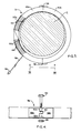
- the system of the invention is generally illustrated in Figure 2, and comprises an annular transformer 31, a voltage detector or voltmeter 38 and a ground potential, which may be a shaft ground brush 39.
- a voltage detector or voltmeter 38 and a ground potential, which may be a shaft ground brush 39.
- brush 39 may be either the ground brush that is normally included within the previously described ASGS, or it may be a brush that has been specially installed onto the shaft 1 for the purposes of the invention.
- the voltmeter 38 may be any one of a number of commercially available voltmeters capable of measuring voltages on the order of 10 to 1000 millivolts ac.
- One end of the voltmeter 38 is preferably connected to the ground brush 39 in order to bring this side of the voltmeter to ground potential, while the other side of the voltmeter is detachably connectable to a portion of the shaft seal 11a,b or the bearings 23 associated with bearing pedestals 17a,b,c,d which are supposed to be insulated from ground potential by the insulating materials 25 or 30.
- Figure 2 illustrates how the voltmeter 38 may be used to check the insulation of the shaft seal 11a.
- the transformer 37 includes an annular core assembly 42 formed from two hingedly connected core halves 43 which are capable of being interlocked around a section of the shaft 1 in much the same fashion as a bangle bracelet is snapped over the wrist of a wearer.
- a plurality of wire windings 44 are coiled around the middle portion of core half 43a. These wire windings form a coil whose input and output are connected to a standard 120 volt plug 46 by means of a double strand of cable 48.
- the wire windings 44 are coiled around recessed portions 50a,b provided in core half 43a.
- 720 windings is preferred due to the fact that the ac voltage that the annular transformer 37 will induce on the shaft 1 when 720 windings are included will come to about 0.170 volts ac.
- the provision of such recessed portions 50a,b protects the inner portion of the wire windings 44 by preventing these windings from being squeezed or braided between the annular core assembly 42, and the outer surface of the shaft 1.
- the upper ends of the two core halves 43a,b are pivotally connected by means of a hinge 54 which allows the core half 43a to be pivoted almost 180.
- a latch assembly 56 is provided for connecting and disconnecting the lower ends of the two core halves 43a,b.
- the latch assembly 56 is formed from a pair of opposing latch plates 58a,b mounted on the lower ends of the core halves 43a,b respectively. These latch plates 58a,b terminate in mutually registerable, interdigitating tubes 60,62a,b through which a latching bolt 64 may be inserted when the tubes 60,62a,b are aligned as shown.
- a nut 66 may be used to secure the latch assembly 56 together.
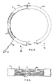
- each of the two halves 43a,b of the annular core assembly 42 is formed from hundreds of insulated laminations 68 of a magnetically conductive metal, such as soft iron, in order to prevent eddy current losses from occurring within the annular core assembly 42.
- Thin layers 70 of an insulating material are preferably interposed between the laminations 68 in order to prevent conductance of such eddy currents.
- each of the ends of the two core halves 43a,b may be provided with two or more fingers 71 which are receivable within complimentarily shaped recesses 72.
- an outer layer of insulation 73 surrounds the exterior of each of the core halves 43 both in order to insulate the annular core 72 from the shaft 1, as well as to structurally rigidify the stack of laminations 68 which forms the two core halves 43a,b.
- the latch bolt 64 is removed from the latch assembly 56, and the two core halves 43a,b are pivotally opened with respect to one another and are slipped over the shaft 1 of a generator 3 in the position illustrated in Figure 3.
- the latch assembly 56 is then closed by means of the bolt 64 and nut 66.
- one side of the voltmeter 38 is electrically connected to the previously described ground brush 39.
- the testing of the insulating material 25, 30 present in both the shaft seals 11a,b and bearing 23 is ready to begin.
- the plug 46 of the annular transformer 37 is plugged into a standard, 120 volt ac power source, such that the annular core assembly 42 and the metal forming the generator shaft 1 coact like a transformer having a 720 turn primary side, and a single turn secondary side. Accordingly, 0.170 volts ac is induced along the longitudinal axis of the shaft 1.
- the system operator proceeds to test the insulating material 25, 30 of the shaft seals 11a,b and bearing pedestals 17a,b,c,d by detachably connecting the left side of the voltmeter 38 to regions of these components which are supposed to be electrically insulated from the shaft 1 by the aforementioned insulating materials.
- the system of the invention advantageously informs the system operator not only of the existence of a leak in the insulating materials 25, 30, but also which specific insulating interface is defective. This constitutes still another significant advantage over the ASGS associated with the prior art, which was only capable of informing the system operator of the existence, but not the location of, a defective insulating interface. Additionally, since most shorts occur while the bearings or seals are being reassembled, the measured voltage (or current) through the shaft brush is preferably constantly monitored during the reassembly process.
- annular core assembly is preferably located in the position shown in Figure 2 for test purposes, it may also be located near the exciter 15 and gradually moved up the shaft 1 to advantageously detect shorts in any of the insulated bearing pedestals 17 a,b,c,d.
Landscapes
- Physics & Mathematics (AREA)
- General Physics & Mathematics (AREA)
- Engineering & Computer Science (AREA)
- Power Engineering (AREA)
- Motor Or Generator Frames (AREA)
- Testing Of Short-Circuits, Discontinuities, Leakage, Or Incorrect Line Connections (AREA)
- Tests Of Circuit Breakers, Generators, And Electric Motors (AREA)
Applications Claiming Priority (2)
| Application Number | Priority Date | Filing Date | Title |
|---|---|---|---|
| US07/666,316 US5134378A (en) | 1991-03-08 | 1991-03-08 | System and method for detecting faults in generator bearing pedestals and seal insulation |
| US666316 | 1991-03-08 |
Publications (2)
| Publication Number | Publication Date |
|---|---|
| EP0503846A2 true EP0503846A2 (fr) | 1992-09-16 |
| EP0503846A3 EP0503846A3 (en) | 1994-05-18 |
Family
ID=24673695
Family Applications (1)
| Application Number | Title | Priority Date | Filing Date |
|---|---|---|---|
| EP19920301909 Withdrawn EP0503846A3 (en) | 1991-03-08 | 1992-03-05 | System and method for detecting faults in generator bearing pedestals and seal insulation |
Country Status (8)
| Country | Link |
|---|---|
| US (1) | US5134378A (fr) |
| EP (1) | EP0503846A3 (fr) |
| JP (1) | JPH07191103A (fr) |
| KR (1) | KR920019044A (fr) |
| CA (1) | CA2062445A1 (fr) |
| CS (1) | CS67592A3 (fr) |
| MX (1) | MX9200958A (fr) |
| TW (1) | TW197540B (fr) |
Cited By (2)
| Publication number | Priority date | Publication date | Assignee | Title |
|---|---|---|---|---|
| WO1997030359A1 (fr) * | 1996-02-14 | 1997-08-21 | Westinghouse Electric Corporation | Procede et dispositif de diagnostic concernant l'impedance d'isolation de paliers propres a une machine electrique tournante |
| US7212010B2 (en) | 2004-08-12 | 2007-05-01 | Alstom Technology Ltd. | Method and device for detecting a contact point on a shaft of a rotating machine |
Families Citing this family (10)
| Publication number | Priority date | Publication date | Assignee | Title |
|---|---|---|---|---|
| MY116924A (en) * | 1996-07-10 | 2004-04-30 | Matsushita Electric Industrial Co Ltd | High speed dynamic run-out testing apparatus and method |
| US6163157A (en) * | 1999-02-17 | 2000-12-19 | General Electric Co. | Insulation tester for squirrel cage rotors |
| US7034706B1 (en) | 1999-05-06 | 2006-04-25 | Nippes Paul I | Early warning and problem detection in rotating machinery by monitoring shaft voltage and/or grounding current |
| US6460013B1 (en) | 1999-05-06 | 2002-10-01 | Paul I. Nippes | Shaft voltage current monitoring system for early warning and problem detection |
| US6798112B1 (en) * | 2003-04-25 | 2004-09-28 | General Motors Corporation | Armature ground locating test process and equipment |
| JP4665689B2 (ja) * | 2005-09-28 | 2011-04-06 | 株式会社日立製作所 | 発電機用軸封装置 |
| DE102015223211A1 (de) * | 2015-11-24 | 2017-05-24 | Robert Bosch Gmbh | Verfahren zum Erkennen eines Fehlers in einer Generatoreinheit |
| CN108828419B (zh) * | 2018-08-01 | 2020-11-03 | 广东电网有限责任公司广州供电局 | 基于似然估计的开关房局部放电定向方法 |
| CN113933668B (zh) * | 2021-11-12 | 2024-05-10 | 中广核核电运营有限公司 | 发电机转子绝缘检测方法及发电机定子故障测试方法 |
| CN115308599B (zh) * | 2022-10-09 | 2023-03-28 | 深圳市兴丰元机电有限公司 | 一种电机用防水测试装置 |
Family Cites Families (10)
| Publication number | Priority date | Publication date | Assignee | Title |
|---|---|---|---|---|
| US3746979A (en) * | 1971-07-08 | 1973-07-17 | V Kildishev | Apparatus for measuring the insulation resistance of the rotor of a brushless synchronous machine |
| US3831160A (en) * | 1973-10-01 | 1974-08-20 | Gen Electric | Voltage and current monitoring system |
| CH594891A5 (fr) * | 1976-04-22 | 1978-01-31 | Bbc Brown Boveri & Cie | |
| US4097794A (en) * | 1976-11-15 | 1978-06-27 | Allis-Chalmers Corporation | Static means for detecting ground insulation failure for rotary electric machines |
| US4492999A (en) * | 1981-05-09 | 1985-01-08 | Mitsubishi Denki Kabushiki Kaisha | Supervisory unit for rotary electrical machinery and apparatus |
| US4517839A (en) * | 1983-07-05 | 1985-05-21 | Unit Rig & Equipment Co. | Off-highway vehicle systems simulator and control panel testing |
| SE456376B (sv) * | 1983-12-08 | 1988-09-26 | Helmersson Rune | Larmanordning vid isolerat rorsystem |
| JPS63169534A (ja) * | 1987-01-08 | 1988-07-13 | Kokusai Denshin Denwa Co Ltd <Kdd> | 光ケ−ブルの障害点検出方式 |
| US4808911A (en) * | 1987-07-22 | 1989-02-28 | Hughes Aircraft Company | Loop resistance test apparatus |
| US4851949A (en) * | 1988-06-13 | 1989-07-25 | Westinghouse Electric Corp. | Brush bounce detection in active shaft ground system |
-
1991
- 1991-03-08 US US07/666,316 patent/US5134378A/en not_active Expired - Fee Related
-
1992
- 1992-02-17 TW TW081101116A patent/TW197540B/zh active
- 1992-03-05 EP EP19920301909 patent/EP0503846A3/en not_active Withdrawn
- 1992-03-05 MX MX9200958A patent/MX9200958A/es not_active IP Right Cessation
- 1992-03-06 JP JP8448892A patent/JPH07191103A/ja not_active Withdrawn
- 1992-03-06 CA CA002062445A patent/CA2062445A1/fr not_active Abandoned
- 1992-03-06 CS CS92675A patent/CS67592A3/cs unknown
- 1992-03-07 KR KR1019920003799A patent/KR920019044A/ko not_active Withdrawn
Cited By (2)
| Publication number | Priority date | Publication date | Assignee | Title |
|---|---|---|---|---|
| WO1997030359A1 (fr) * | 1996-02-14 | 1997-08-21 | Westinghouse Electric Corporation | Procede et dispositif de diagnostic concernant l'impedance d'isolation de paliers propres a une machine electrique tournante |
| US7212010B2 (en) | 2004-08-12 | 2007-05-01 | Alstom Technology Ltd. | Method and device for detecting a contact point on a shaft of a rotating machine |
Also Published As
| Publication number | Publication date |
|---|---|
| CA2062445A1 (fr) | 1992-09-09 |
| EP0503846A3 (en) | 1994-05-18 |
| CS67592A3 (en) | 1992-10-14 |
| KR920019044A (ko) | 1992-10-22 |
| TW197540B (fr) | 1993-01-01 |
| MX9200958A (es) | 1992-09-01 |
| US5134378A (en) | 1992-07-28 |
| JPH07191103A (ja) | 1995-07-28 |
Similar Documents
| Publication | Publication Date | Title |
|---|---|---|
| Albright | Interturn short-circuit detector for turbine-generator rotor windings | |
| US5134378A (en) | System and method for detecting faults in generator bearing pedestals and seal insulation | |
| Stone | Condition monitoring and diagnostics of motor and stator windings–A review | |
| US4156846A (en) | Detection of arcing faults in generator windings | |
| Stone et al. | Application of partial discharge testing to motor and generator stator winding maintenance | |
| Paoletti et al. | Partial discharge theory and technologies related to medium-voltage electrical equipment | |
| US5032826A (en) | Core monitor that uses rotor shaft voltages | |
| Stone et al. | Impact of slot discharges and vibration sparking on stator winding life in large generators | |
| Timperley et al. | Condition assessment of electrical apparatus with EMI diagnostics | |
| Stone et al. | Examples of stator winding insulation deterioration in new generators | |
| Stone et al. | Unusual PD pulse phase distributions in operating rotating machines | |
| Istad et al. | A review of results from thermal cycling tests of hydrogenerator stator windings | |
| Stone et al. | Monitoring of shaft voltages and grounding currents in rotating machines | |
| Verginadis et al. | Determination of the insulation condition in synchronous generators: Industrial methods and a case study | |
| Yasid et al. | The Effect of short circuit fault in three-phase core-typed transformer | |
| Pedneault-Desroches et al. | Shaft current measurement and failure prediction in hydrogenerators | |
| Timperley et al. | Estimating the remaining service life of asphalt-mica stator insulation | |
| Emery et al. | On Line Incipient ARC Detection in Large Turbine Generator Stator Winding | |
| EP3940407B1 (fr) | Dispositif de surveillance de résistance d'isolation | |
| McDermid et al. | Analysis of converter transformer failures and application of periodic on-line partial discharge measurements | |
| CN101479615B (zh) | 用于诊断在线高压部件的方法和设备 | |
| Kogan et al. | Surface corona suppression in high voltage stator winding end turns | |
| Engelen et al. | On-site partial discharge diagnostics of cast-resin transformers | |
| Aksyonov et al. | On-line a off-line diagnostics for power station HV equipment | |
| Fujinami et al. | Development of detection method with a magnetic field sensor for incomplete contact in gas insulated switches and bus connecting parts |
Legal Events
| Date | Code | Title | Description |
|---|---|---|---|
| PUAI | Public reference made under article 153(3) epc to a published international application that has entered the european phase |
Free format text: ORIGINAL CODE: 0009012 |
|
| AK | Designated contracting states |
Kind code of ref document: A2 Designated state(s): CH DE ES GB LI |
|
| PUAL | Search report despatched |
Free format text: ORIGINAL CODE: 0009013 |
|
| AK | Designated contracting states |
Kind code of ref document: A3 Designated state(s): CH DE ES GB LI |
|
| 17P | Request for examination filed |
Effective date: 19941118 |
|
| 17Q | First examination report despatched |
Effective date: 19960509 |
|
| 18D | Application deemed to be withdrawn |
Effective date: 19960920 |