EP0503539B1 - Procédé pour le traitement d'une pièce à usiner au moyen du laser - Google Patents
Procédé pour le traitement d'une pièce à usiner au moyen du laser Download PDFInfo
- Publication number
- EP0503539B1 EP0503539B1 EP92104009A EP92104009A EP0503539B1 EP 0503539 B1 EP0503539 B1 EP 0503539B1 EP 92104009 A EP92104009 A EP 92104009A EP 92104009 A EP92104009 A EP 92104009A EP 0503539 B1 EP0503539 B1 EP 0503539B1
- Authority
- EP
- European Patent Office
- Prior art keywords
- workpiece
- laser beam
- gas jet
- nozzle
- gas
- Prior art date
- Legal status (The legal status is an assumption and is not a legal conclusion. Google has not performed a legal analysis and makes no representation as to the accuracy of the status listed.)
- Expired - Lifetime
Links
- 238000000034 method Methods 0.000 title claims description 22
- 239000007789 gas Substances 0.000 claims description 29
- 239000000463 material Substances 0.000 claims description 22
- 238000003754 machining Methods 0.000 claims description 13
- 239000000203 mixture Substances 0.000 claims description 8
- 230000005686 electrostatic field Effects 0.000 claims description 4
- 239000011261 inert gas Substances 0.000 claims description 2
- 239000000428 dust Substances 0.000 description 7
- 239000002245 particle Substances 0.000 description 7
- 238000007786 electrostatic charging Methods 0.000 description 5
- 239000007787 solid Substances 0.000 description 5
- 230000000694 effects Effects 0.000 description 3
- 239000000758 substrate Substances 0.000 description 3
- 239000002801 charged material Substances 0.000 description 2
- 230000003287 optical effect Effects 0.000 description 2
- 239000011364 vaporized material Substances 0.000 description 2
- 238000007600 charging Methods 0.000 description 1
- 238000010586 diagram Methods 0.000 description 1
- 230000005670 electromagnetic radiation Effects 0.000 description 1
- 238000001704 evaporation Methods 0.000 description 1
- 238000010438 heat treatment Methods 0.000 description 1
- 239000002655 kraft paper Substances 0.000 description 1
- 238000002372 labelling Methods 0.000 description 1
- 239000002184 metal Substances 0.000 description 1
- 229910052751 metal Inorganic materials 0.000 description 1
- 150000002739 metals Chemical class 0.000 description 1
- 238000003801 milling Methods 0.000 description 1
- 239000004033 plastic Substances 0.000 description 1
- 229920003023 plastic Polymers 0.000 description 1
- 230000005855 radiation Effects 0.000 description 1
- 238000007142 ring opening reaction Methods 0.000 description 1
- 239000005060 rubber Substances 0.000 description 1
- 239000004065 semiconductor Substances 0.000 description 1
- 238000007711 solidification Methods 0.000 description 1
- 230000008023 solidification Effects 0.000 description 1
Images

Classifications
-
- B—PERFORMING OPERATIONS; TRANSPORTING
- B23—MACHINE TOOLS; METAL-WORKING NOT OTHERWISE PROVIDED FOR
- B23K—SOLDERING OR UNSOLDERING; WELDING; CLADDING OR PLATING BY SOLDERING OR WELDING; CUTTING BY APPLYING HEAT LOCALLY, e.g. FLAME CUTTING; WORKING BY LASER BEAM
- B23K26/00—Working by laser beam, e.g. welding, cutting or boring
- B23K26/16—Removal of by-products, e.g. particles or vapours produced during treatment of a workpiece
Definitions
- the invention relates to a method for workpiece machining, in particular for surface machining, with a laser beam focused on the workpiece and an additional gas jet directed at the focal point of the laser beam, material of the workpiece being removed from the workpiece by the focused laser beam with the aid of the directed gas jet.
- the dust particles are removed without evaporating the dust particles or the material of the surface of the solid substrate.
- the laser radiation is not focused, but rather directed flat onto the surface.
- a particle-free gas can be used to help clean the surface of dust particles.
- the invention is therefore based on the object of demonstrating a method of the type mentioned which avoids the disadvantages mentioned in a simple manner and prevents the evaporated material from condensing again and being deposited again on the workpiece surface.
- This object is achieved in that the workpiece to be machined is charged electrostatically.
- the evaporated material Due to the electrostatic charging of the workpiece to be machined according to the invention, the evaporated material also receives an equipolar electrostatic charge. Because of this charge, an electrostatic repulsive force acts on the evaporated material against the workpiece, which prevents the solidification of the evaporated material from re-attaching to the machined workpiece. This results in a significant increase in the quality of material processing with lasers while increasing the material removal rate. This applies in particular to surface processing when only partially processing the surface, such as when engraving or labeling.
- the gas jet can be composed of inert gases such as He, Ar, N2 or mixtures thereof or by reactive gases such as O2, CO2, mixtures thereof or CO2- and / or O2-containing gas mixtures.
- inert gases such as He, Ar, N2 or mixtures thereof
- reactive gases such as O2, CO2, mixtures thereof or CO2- and / or O2-containing gas mixtures.
- a gas composition of inert and reactive gas has an advantageous effect in the process according to the invention.
- the reactive gas supports the removal of the material from the workpiece.
- an electrostatic field is generated in the space between the workpiece surface and the nozzle, through which the laser beam and gas jet are directed against the workpiece.
- a body is charged electrostatically with the opposite polarity to the workpiece.
- the vaporized material has an attractive force due to the oppositely charged body. The evaporated material therefore does not accumulate again on the workpiece surface, but on the body with the opposite polarity.
- the nozzle head itself or, with particular advantage, an electrode which is located between the workpiece surface and the nozzle can be used.
- An additional electrode has the decisive advantage that material deposits of the evaporated material on it are unproblematic and that the electrode can be easily replaced. There is thus a workpiece machining with material removal in the desired direction, i.e. towards the electrode and away from the machined workpiece surface.
- a ring electrode is used as the electrode, which is arranged rotationally symmetrically to the laser beam axis or to the direction of flow of the gas jet, so that the laser beam and gas jet are guided through the ring opening of the electrode.
- the ring electrode can be designed as a torrus or as a perforated disc.
- the method according to the invention is suitable for processing any material that is electrostatically chargeable. Examples include metals, semiconductors, plastics and rubber.
- the workpiece to be machined is preferably charged positively.
- the nozzle is charged with the same polarity as the workpiece to be machined. This prevents the evaporated material from attaching to the nozzle.
- the same-pole electrostatic charging of the nozzle has a particularly advantageous effect if an electrode with opposite polarity is charged between the nozzle and the workpiece. This ensures that no material builds up in the nozzle channel or can even reach the focusing lens.
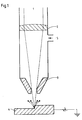
- FIG. 1 shows a diagram of the workpiece machining according to the invention with a laser.
- the parallel incident laser beam 1 is focused in a nozzle head by a focusing lens 2.
- the focused laser beam is guided through the nozzle 3 onto the workpiece 4, the focal point of the focused laser beam being on the workpiece surface of the workpiece to be machined.
- Inert and / or reactive gas is pumped into the nozzle head via a lateral gas supply line 5.
- a sharp gas jet is formed, which against the Machining point of the workpiece is guided. According to the invention, this was charged electrostatically, in the exemplary embodiment positively.
- the removed, also positively charged material is repelled from the workpiece, so that high-quality workpiece processing is made possible.
- FIG. 2 also shows a schematic of the workpiece machining according to the invention with a laser, which essentially corresponds to that from FIG. 1.
- the reference numbers 1 to 5 are therefore adopted identically.
- an annular electrode 6 in the form of a perforated disk is additionally used. While the workpiece is at a positive potential as in FIG. 1, the ring electrode 6 in FIG. 2 is negatively charged electrostatically. Evaporated positively charged material is consequently attracted to the ring electrode and therefore accumulates on the ring electrode.
Landscapes
- Engineering & Computer Science (AREA)
- Physics & Mathematics (AREA)
- Optics & Photonics (AREA)
- Plasma & Fusion (AREA)
- Mechanical Engineering (AREA)
- Laser Beam Processing (AREA)
Claims (9)
- Procédé d'usinage de pièces, en particulier pour l'usinage de surfaces, à l'aide d'un rayon laser (1) focalisé sur la pièce (4) et d'un jet de gaz supplémentaire (5) dirigé sur le foyer du rayon laser (1), dans lequel le matériau de la pièce est éliminé de la pièce par le rayon laser (1) avec l'assistance du jet de gaz dirigé (5), caractérisé en ce que la pièce à usiner (4) est chargée électrostatiquement.
- Procédé selon la revendication 1, caractérisé en ce que le jet de gaz (5) est constitué de gaz inerte tels que He, Ar, N2, ou leurs mélanges.
- Procédé selon la revendication 1, caractérisé en ce que le jet de gaz (5) est constitué de gaz réactif tel que O₂, CO₂, de leurs mélanges ou d'un mélange de gaz contenant du CO₂ et/ou O₂.
- Procédé selon la revendication 2 ou 3, caractérisé en ce que le jet de gaz (5) est constitué d'un mélange de gaz inerte et de gaz réactif.
- Procédé selon l'une des revendications 1 à 4, caractérisé en ce que dans l'espace entre la surface de la pièce (4) et la buse (3), par le rayon laser (1) et les jets de gaz (5) guidés contre la pièce (4), on établit au moins dans la zone spatiale située au-dessus de la surface de la pièce un champ électrostatique.
- Procédé selon la revendication 5, caractérisé en ce que le champ électrostatique est créé par un corps (6) chargé à contrepolarité par rapport à la pièce (4) à usiner et qui se trouve entre la surface de la pièce (4) et la buse (3).
- Procédé selon la revendication 6, caractérisé en ce qu'on utilise pour la création du champ électrostatique une électrode annulaire (6) entre la buse (3) et la pièce (4) qui est traversée par le rayon laser (1) et le jet de gaz (5).
- Procédé selon l'une des revendications 1 à 7, caractérisé en ce que la pièce (4) est chargée électrostatiquement de façon positive.
- Procédé selon l'une des revendications 1 à 8, caractérisé en ce que la buse (3) est chargée électrostatiquement avec la même polarité que la pièce à usiner (4).
Applications Claiming Priority (2)
| Application Number | Priority Date | Filing Date | Title |
|---|---|---|---|
| DE4108541A DE4108541A1 (de) | 1991-03-15 | 1991-03-15 | Verfahren zur werkstueckbearbeitung mit einem laser |
| DE4108541 | 1991-03-15 |
Publications (2)
| Publication Number | Publication Date |
|---|---|
| EP0503539A1 EP0503539A1 (fr) | 1992-09-16 |
| EP0503539B1 true EP0503539B1 (fr) | 1994-10-26 |
Family
ID=6427425
Family Applications (1)
| Application Number | Title | Priority Date | Filing Date |
|---|---|---|---|
| EP92104009A Expired - Lifetime EP0503539B1 (fr) | 1991-03-15 | 1992-03-09 | Procédé pour le traitement d'une pièce à usiner au moyen du laser |
Country Status (3)
| Country | Link |
|---|---|
| EP (1) | EP0503539B1 (fr) |
| AU (1) | AU648646B2 (fr) |
| DE (2) | DE4108541A1 (fr) |
Families Citing this family (5)
| Publication number | Priority date | Publication date | Assignee | Title |
|---|---|---|---|---|
| DE4240190A1 (de) * | 1992-11-30 | 1994-06-01 | Linde Ag | Verfahren zum materialabtragenden Bearbeiten eines Werkstückes mittels eines Laserstrahles und Laserdüse |
| JP3303787B2 (ja) | 1998-08-24 | 2002-07-22 | 株式会社村田製作所 | 電極の切除方法 |
| DE102005005709B4 (de) * | 2005-01-31 | 2009-06-10 | Technische Universität Dresden | Einrichtung zur Bearbeitung von Materialoberflächen |
| CN102899660B (zh) * | 2012-08-28 | 2014-07-23 | 张家港市和昊激光科技有限公司 | 一种提高激光熔覆效果的方法及喷头 |
| CN115156198B (zh) * | 2022-08-16 | 2025-02-25 | 南京航空航天大学 | 一种静电场辅助提高金属板材表面除漆质量的方法 |
Family Cites Families (4)
| Publication number | Priority date | Publication date | Assignee | Title |
|---|---|---|---|---|
| GB2163692B (en) * | 1984-08-30 | 1988-11-30 | Ferranti Plc | Laser apparatus |
| DK168593B1 (da) * | 1985-05-09 | 1994-05-02 | Aga Ab | Fremgangsmåde ved laserskæring af metalliske emner |
| DE3904969A1 (de) * | 1988-02-24 | 1989-09-21 | Schmidt Ott Andreas Dr | Verfahren zur beseitigung von staubpartikeln von oberflaechen in gasfoermiger umgebung |
| DE3824048A1 (de) * | 1988-07-15 | 1990-05-03 | Fraunhofer Ges Forschung | Verfahren und vorrichtung zum bearbeiten von werkstuecken mit laserstrahlung |
-
1991
- 1991-03-15 DE DE4108541A patent/DE4108541A1/de not_active Withdrawn
-
1992
- 1992-03-09 DE DE59200673T patent/DE59200673D1/de not_active Expired - Fee Related
- 1992-03-09 EP EP92104009A patent/EP0503539B1/fr not_active Expired - Lifetime
- 1992-03-11 AU AU12172/92A patent/AU648646B2/en not_active Ceased
Also Published As
| Publication number | Publication date |
|---|---|
| DE4108541A1 (de) | 1992-09-17 |
| AU1217292A (en) | 1992-09-17 |
| EP0503539A1 (fr) | 1992-09-16 |
| AU648646B2 (en) | 1994-04-28 |
| DE59200673D1 (de) | 1994-12-01 |
Similar Documents
| Publication | Publication Date | Title |
|---|---|---|
| DE3942050B4 (de) | Vorrichtung zur Laserplasmaspritzung mit axialer Strömung | |
| DE10128565B4 (de) | Thermisches Plasmaspritzen mit auf einen Draht übertragenem Lichtbogen mit hoher Abscheidungsgeschwindigkeit und Vorrichtung | |
| DE1946909A1 (de) | Einrichtung zum Plattieren von Metalloberflaechen | |
| DE102015016674B4 (de) | Vorrichtung und Verfahren zum Schutz einer Laseroptik | |
| DE3942048A1 (de) | Verfahren und vorrichtung zum laserschweissen | |
| DE3942049A1 (de) | Verfahren und vorrichtung zum erzeugen von einspeisungsmaterialstroemen mittels transversallaserstrahlduesen | |
| DE102020207360A1 (de) | Verfahren zum Herstellen eines Reibbremskörpers | |
| DE1190112B (de) | Vorrichtung zur Erzeugung eines Elektronenstrahlbuendels hoher Stromstaerke und Verfahren zum Erhitzen und Schmelzen mittels einer solchen Vorrichtung | |
| EP0503539B1 (fr) | Procédé pour le traitement d'une pièce à usiner au moyen du laser | |
| EP0743128B1 (fr) | Procédé et dispositif pour le marquage de produits en matériaux transparents (solides) au moyen d'un laser | |
| DE102013226678A1 (de) | EUV-Lithographiesystem und Transporteinrichtung zum Transport eines reflektiven optischen Elements | |
| AT404905B (de) | Anlage zum aufbringen einer spritzschicht auf eine ebene oder gekrümmte fläche eines werkstückes | |
| DE112019005544T5 (de) | Vorrichtung zur Herstellung der dreidimensionalen Objekte | |
| DE202015009154U1 (de) | Vorrichtung zur Lichtbogen-Plasma-Oberflächenreinigung von Metallerzeugnissen und eine Einrichtung hierfür | |
| DE3029104A1 (de) | Verfahren und vorrichtung zur fokuskorrektur bei bearbeitungslasern | |
| DE102016222947A1 (de) | Vorrichtung und Verfahren zur additiven Herstellung eines dreidimensionalen Produktes | |
| DE102021123027A1 (de) | Laser-Bearbeitungsvorrichtung | |
| DE19946182C2 (de) | Verfahren zur Herstellung von Kohlenstoff Nanoröhren | |
| DE1765852B2 (de) | Verfahren und Vorrichtung zur Bearbeitung von metallischen Werkstoffen mit magnetisch fokussieren Ladungsträgerstrahlen | |
| DE102015008921A1 (de) | Verfahren zur additiven Herstellung von Bauteilen | |
| EP0304505B1 (fr) | Dispositif pour le soudage de pièces au moyen d'un faisceau laser | |
| EP0600249B1 (fr) | Procédé pour l'usinage d'une pièce par enlèvement de matière avec un rayon et une buse laser | |
| DE10154093A1 (de) | Verfahren zur Oberflächenbehandlung durch einen Pulverwerkstoff mit Hilfe eines Laserstrahls | |
| DE10016534C2 (de) | Verfahren und Vorrichtung zum Staubschutz in einer Laserbearbeitungsvorrichtung | |
| WO1992010321A1 (fr) | Procede et dispositif d'ebavurage thermique de pieces |
Legal Events
| Date | Code | Title | Description |
|---|---|---|---|
| PUAI | Public reference made under article 153(3) epc to a published international application that has entered the european phase |
Free format text: ORIGINAL CODE: 0009012 |
|
| AK | Designated contracting states |
Kind code of ref document: A1 Designated state(s): DE FR GB IT NL |
|
| 17P | Request for examination filed |
Effective date: 19921005 |
|
| 17Q | First examination report despatched |
Effective date: 19930715 |
|
| GRAA | (expected) grant |
Free format text: ORIGINAL CODE: 0009210 |
|
| AK | Designated contracting states |
Kind code of ref document: B1 Designated state(s): DE FR GB IT NL |
|
| PG25 | Lapsed in a contracting state [announced via postgrant information from national office to epo] |
Ref country code: IT Free format text: LAPSE BECAUSE OF FAILURE TO SUBMIT A TRANSLATION OF THE DESCRIPTION OR TO PAY THE FEE WITHIN THE PRESCRIBED TIME-LIMIT;WARNING: LAPSES OF ITALIAN PATENTS WITH EFFECTIVE DATE BEFORE 2007 MAY HAVE OCCURRED AT ANY TIME BEFORE 2007. THE CORRECT EFFECTIVE DATE MAY BE DIFFERENT FROM THE ONE RECORDED. Effective date: 19941026 Ref country code: GB Effective date: 19941026 Ref country code: NL Effective date: 19941026 Ref country code: FR Effective date: 19941026 |
|
| REF | Corresponds to: |
Ref document number: 59200673 Country of ref document: DE Date of ref document: 19941201 |
|
| EN | Fr: translation not filed | ||
| NLV1 | Nl: lapsed or annulled due to failure to fulfill the requirements of art. 29p and 29m of the patents act | ||
| GBV | Gb: ep patent (uk) treated as always having been void in accordance with gb section 77(7)/1977 [no translation filed] |
Effective date: 19941026 |
|
| PLBE | No opposition filed within time limit |
Free format text: ORIGINAL CODE: 0009261 |
|
| STAA | Information on the status of an ep patent application or granted ep patent |
Free format text: STATUS: NO OPPOSITION FILED WITHIN TIME LIMIT |
|
| 26N | No opposition filed | ||
| PGFP | Annual fee paid to national office [announced via postgrant information from national office to epo] |
Ref country code: DE Payment date: 19990323 Year of fee payment: 8 |
|
| PG25 | Lapsed in a contracting state [announced via postgrant information from national office to epo] |
Ref country code: DE Free format text: LAPSE BECAUSE OF NON-PAYMENT OF DUE FEES Effective date: 20010103 |