EP0503481B1 - Method for applying wrap-around labels to articles - Google Patents
Method for applying wrap-around labels to articles Download PDFInfo
- Publication number
- EP0503481B1 EP0503481B1 EP92103782A EP92103782A EP0503481B1 EP 0503481 B1 EP0503481 B1 EP 0503481B1 EP 92103782 A EP92103782 A EP 92103782A EP 92103782 A EP92103782 A EP 92103782A EP 0503481 B1 EP0503481 B1 EP 0503481B1
- Authority
- EP
- European Patent Office
- Prior art keywords
- labels
- process according
- carrier strip
- corona discharge
- discharge wire
- Prior art date
- Legal status (The legal status is an assumption and is not a legal conclusion. Google has not performed a legal analysis and makes no representation as to the accuracy of the status listed.)
- Expired - Lifetime
Links
Images
Classifications
-
- B—PERFORMING OPERATIONS; TRANSPORTING
- B65—CONVEYING; PACKING; STORING; HANDLING THIN OR FILAMENTARY MATERIAL
- B65C—LABELLING OR TAGGING MACHINES, APPARATUS, OR PROCESSES
- B65C9/00—Details of labelling machines or apparatus
- B65C9/0015—Preparing the labels or articles, e.g. smoothing, removing air bubbles
-
- B—PERFORMING OPERATIONS; TRANSPORTING
- B65—CONVEYING; PACKING; STORING; HANDLING THIN OR FILAMENTARY MATERIAL
- B65C—LABELLING OR TAGGING MACHINES, APPARATUS, OR PROCESSES
- B65C9/00—Details of labelling machines or apparatus
- B65C9/20—Gluing the labels or articles
- B65C9/24—Gluing the labels or articles by heat
Definitions
- the invention relates to a method for all-round labeling of objects, in particular cylindrical battery bodies, in which labels provided on the underside with a layer of pressure-sensitive adhesive are fed to the objects on a carrier tape on which they releasably adhere, in which the labels in front of the objects by deflecting the carrier tape from the Carrier tape can be released and in which the labels are glued to the objects and the lower edge areas of the labels in an overlap area on opposite upper edge areas of the same labels.
- a pretreatment of surfaces to be labeled by flame, abrasion, corona treatment or glow discharge is known from DE-24 46 373 C2, a chemical pretreatment from the book by the buyer, Helmut, "Working with plastics", volume 2, processing, Berlin, Heidelberg , New York 1981, Table 8.4.
- the object of the invention is to provide a method according to the preamble of claim 1, which avoids the lifting of the labels from each other in the overlapping areas in a simple manner.
- the method is characterized in that the surface energy of the tops of the labels at least in the top edge areas to increase the adhesive strength of the pressure-sensitive adhesive layer on them is increased by at least one corona pretreatment immediately before the deflection.
- At least one corona discharge wire is preferably arranged above the base plate at a distance from the labels on the carrier tape, transversely to the direction of movement of the carrier tape.
- the overlap area has a width of 3 to 5 mm, so that a distance between the overlap area and the corona discharge wire of approximately 10 mm is particularly suitable in order to achieve a uniform pretreatment in the edge area mentioned.
- the corona treatment with a corona discharge wire or each corona discharge wire should be 2 to 5 ms, preferably 3 to 4 ms.
- the corona discharge wire with an electrical one Power from 100 W to 300 W per 100 mm length, preferably 150 to 200 W per 100 mm length at a voltage of 20 to 35 kV, in particular 25 to 30 kV, with a frequency of 15 to 25 kHz, in particular 18 to 22 kHz to feed.
- the surface energy should be increased considerably, namely to more than 40 mN per m, in particular more than 45 mN per m.
- the labels contain a metal layer, in particular a metal layer produced by vapor deposition and plastic layers adjacent to this metal layer, it can happen that the metal layers evaporate during the corona treatment and the plastic layers melt, as a result of which the labels are at least damaged on the edges.
- the overlap regions are preferably made wider than those edge regions of the labels which can receive edge defects through the pretreatment.
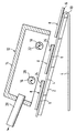
- a base plate 2 is shown in section, over which a carrier tape 4, on which there are labels 8 provided on the underside with a pressure-sensitive adhesive layer 6, is drawn around a deflection edge 10.
- the labels 8 with their pressure-sensitive adhesive layer 6 detach from the carrier tape 4 in a known manner in order to be applied to objects to be labeled.
- a corona discharge device is located above the base plate 2 12 with a shielding housing 14 and two corona discharge wires 16, 18 arranged in the direction of movement of the carrier tape 4.
- the corona discharge wires 16, 18 are enclosed by quartz glass cylinders 20, 22.
- the front upper edge regions 24, 26 of the labels in the direction of movement are corona-treated in two steps.
- the dimensions and dimensions are preferably as stated above. Harmful gases released during the corona treatment are extracted by a suction device 28.
- the corona treatment can also be carried out in such a way that it is used for other purposes.
- the labels are still printed after they have been applied to the objects, for example by means of an inkjet printing process.
- the compressive strength is increased if there are remnants of the corona treatment on the surfaces of the labels.
Abstract
Description
Die Erfindung betrifft ein Verfahren zum Rundumetikettieren von Gegenständen, insbesondere von zylindrischen Batteriekörpern, bei dem unterseitig mit einer Haftklebstoffschicht versehene Etiketten den Gegenständen auf einem Trägerband zugeführt werden, auf dem sie lösbar haften, bei dem die Etiketten vor den Gegenständen durch Umlenken des Trägerbands von dem Trägerband gelöst werden und bei dem die Etiketten auf die Gegenstände und dabei unterseitige Randbereiche der Etiketten in einem Überlappungsbereich auf gegenüberliegende oberseitige Randbereiche der jeweils gleichen Etiketten geklebt werden.The invention relates to a method for all-round labeling of objects, in particular cylindrical battery bodies, in which labels provided on the underside with a layer of pressure-sensitive adhesive are fed to the objects on a carrier tape on which they releasably adhere, in which the labels in front of the objects by deflecting the carrier tape from the Carrier tape can be released and in which the labels are glued to the objects and the lower edge areas of the labels in an overlap area on opposite upper edge areas of the same labels.
Bei einem aus der DE-34 30 162 C2 bekannten Verfahren dieser Art hat sich gezeigt, daß sich gelegentlich die Überlappungsbereiche bei hohen Rückstellkräften der Etiketten voneinander abheben, wenn die Rückstellkräfte größer sind als die Klebekraft in den genannten Überlappungsbereichen. Diese Rückstellkräfte sind u. a. von der Biegesteifagkeit der verwendeten Etiketten sowie von der Krümmung der zu etikettierenden Gegenstände in dem Überlappungsbereich abhängig.In a method of this type known from DE-34 30 162 C2, it has been shown that the overlap regions occasionally stand out from one another at high restoring forces of the labels if the restoring forces are greater than the adhesive force in the mentioned overlap regions. These restoring forces are u. a. dependent on the bending stiffness of the labels used and on the curvature of the objects to be labeled in the overlap area.
Eine Vorbehandlung von zu etikettierenden Oberflächen durch Beflammung, Abrasion, Koronabehandlung oder Glimmentladung ist aus der DE-24 46 373 C2 bekannt, eine chemische Vorbehandlung aus dem Buch von Käufer, Helmut, "Arbeiten mit Kunststoffen", Band 2, Verarbeitung, Berlin, Heidelberg, New York 1981, Tabelle 8.4.A pretreatment of surfaces to be labeled by flame, abrasion, corona treatment or glow discharge is known from DE-24 46 373 C2, a chemical pretreatment from the book by the buyer, Helmut, "Working with plastics",
Aufgabe der Erfindung ist es, ein Verfahren nach dem Oberbegriff des Anspruchs 1 anzugeben, das das Abheben der Etiketten voneinander in den Überlappungsbereichen in einfacher Weise vermeidet.The object of the invention is to provide a method according to the preamble of claim 1, which avoids the lifting of the labels from each other in the overlapping areas in a simple manner.
Zur Lösung dieser Aufgabe ist das Verfahren dadurch gekennzeichnet, daß die Oberflächenenergie der Oberseiten der Etiketten wenigstens in den oberseitigen Randbereichen zur Erhöhung der Klebekraft der Haftklebstoffschicht an ihnen durch eine mindestens einmalige Korona-Vorbehandlung unmittelbar vor dem Umlenken erhöht wird.To achieve this object, the method is characterized in that the surface energy of the tops of the labels at least in the top edge areas to increase the adhesive strength of the pressure-sensitive adhesive layer on them is increased by at least one corona pretreatment immediately before the deflection.
Erfolgt das Umlenken des Trägerbands - wie an sich bekannt - am Ende einer Unterlagsplatte, so wird bevorzugt oberhalb der Unterlagsplatte in Abstand von den auf dem Trägerband befindlichen Etiketten wenigstens ein Koronaentladungsdraht quer zur Bewegungsrichtung des Trägerbands angeordnet.If the carrier tape is deflected, as is known per se, at the end of a base plate, at least one corona discharge wire is preferably arranged above the base plate at a distance from the labels on the carrier tape, transversely to the direction of movement of the carrier tape.
Dabei hat es sich bewährt, den Koronaentladungsdraht in einem dielektrischen Zylinder einzubetten. In der Praxis wurden besonders gute Ergebnisse erzielt, wenn das Verhältnis der Abmessungen von Abstand zwischen Etiketten und Koronaentladungsdraht zu Überlappungsbereich 0,5 bis 4, vorzugsweise 1 bis 2, beträgt und wenn der Durchmesser des dielektrischen Zylinders das 0,6- bis 1,4-fache, vorzugsweise das 0,8- bis 1,2-fache, des Abstands beträgt.It has proven useful to embed the corona discharge wire in a dielectric cylinder. In practice, particularly good results have been achieved if the ratio of the dimensions of the distance between the label and the corona discharge wire to the overlap area is 0.5 to 4, preferably 1 to 2, and if the diameter of the dielectric cylinder is 0.6 to 1.4 times, preferably 0.8 to 1.2 times, the distance.
In der Mehrzahl der Fälle hat der Uberlappungsbereich eine Breite von 3 bis 5 mm, so daß ein Abstand zwischen Überlappungsbereich und Koronaentladungsdraht von etwa 10 mm besonders geeignet ist, um eine gleichmäßige Vorbehandlung in dem genannten Randbereich zu erzielen.In the majority of cases, the overlap area has a width of 3 to 5 mm, so that a distance between the overlap area and the corona discharge wire of approximately 10 mm is particularly suitable in order to achieve a uniform pretreatment in the edge area mentioned.
Dabei sollte die Koronabehandlung mit einem Koronaentladungsdraht bzw. jedem Koronaentladungsdraht 2 bis 5 ms, vorzugsweise 3 bis 4 ms, betragen.The corona treatment with a corona discharge wire or each corona discharge wire should be 2 to 5 ms, preferably 3 to 4 ms.
Um die Oberflächenenergie hinreichend zu erhöhen, hat es sich bewährt, dem Koronaentladungsdraht eine elektrische Leistung von 100 W bis 300 W pro 100 mm Länge, vorzugsweise 150 bis 200 W pro 100 mm Länge bei einer Spannung von 20 bis 35 kV, insbesondere 25 bis 30 kV, mit einer Frequenz von 15 bis 25 kHz, insbesondere 18 bis 22 kHz, zuzuführen.In order to increase the surface energy sufficiently, it has proven useful to provide the corona discharge wire with an electrical one Power from 100 W to 300 W per 100 mm length, preferably 150 to 200 W per 100 mm length at a voltage of 20 to 35 kV, in particular 25 to 30 kV, with a frequency of 15 to 25 kHz, in particular 18 to 22 kHz to feed.
In der Regel soll die Oberflächenenergie erheblich erhöht werden, nämlich auf mehr als 40 mN pro m, insbesondere mehr als 45 mN pro m.As a rule, the surface energy should be increased considerably, namely to more than 40 mN per m, in particular more than 45 mN per m.
Enthalten die Etiketten eine Metallschicht, insbesondere eine durch Bedampfung erzeugte Metallschicht und an dieser Metallschicht angrenzende Kunststoffschichten, so kann es geschehen, daß die Metallschichten bei der Koronabehandlung verdampfen und die Kunststoffschichten schmelzen, wodurch die Etiketten wenigstens randseitig beschädigt werden. Um dennoch die erhöhte Oberflächenenergie aufbringen zu können, ohne daß solche Schäden am etikettierten Gegenstand bemerkbar und schädlich werden, werden bevorzugt die Uberlappungsbereiche breiter gemacht als diejenigen Randbereiche der Etiketten, die durch die Vorbehandlung Randfehler erhalten können.If the labels contain a metal layer, in particular a metal layer produced by vapor deposition and plastic layers adjacent to this metal layer, it can happen that the metal layers evaporate during the corona treatment and the plastic layers melt, as a result of which the labels are at least damaged on the edges. In order nevertheless to be able to apply the increased surface energy without such damage to the labeled object becoming noticeable and harmful, the overlap regions are preferably made wider than those edge regions of the labels which can receive edge defects through the pretreatment.
Im folgenden wird eine Vorrichtung zur Durchführung des Verfahrens unter Hinweis auf die beigefügten Zeichnung beschrieben.In the following an apparatus for performing the method is described with reference to the accompanying drawing.
In der Zeichnung ist im Schnitt eine Unterlagsplatte 2 dargestellt, über die ein Trägerband 4, auf dem sich unterseitig mit einer Haftklebstoffschicht 6 versehene Etiketten 8 befinden, um eine Umlenkkante 10 gezogen wird. An der Umlenkkante 10 lösen sich die Etiketten 8 mit ihrer Haftklebstoffschicht 6 in bekannter Weise vom Trägerband 4, um auf zu etikettierende Gegenstände aufgebracht zu werden.In the drawing, a
Über der Unterlagsplatte 2 ist eine Koronaentladungseinrichtung 12 mit einem Abschirmgehäuse 14 und in Bewegungsrichtung des Trägerbands 4 zwei Koronaentladungsdrähten 16, 18 angeordnet. Die Koronaentladungsdrähte 16, 18 sind von Quarzglaszylindern 20, 22 umschlossen.A corona discharge device is located above the
In dem dargestellten Zustand werden die in Bewegungsrichtung vorderen oberen Randbereiche 24, 26 der Etiketten in zwei Schritten koronabehandelt. Die Abmessungen und Bemessungen sind bevorzugt so, wie oben angegeben. Bei der Koronabehandlung freiwerdende schädliche Gase werden durch eine Absaugvorrichtung 28 abgesaugt.In the state shown, the front
Die Koronabehandlung kann auch so durchgeführt werden, daß sie noch anderen Zwecken nutzt. Beispielsweise werden die Etiketten nach ihrem Aufbringen auf die Gegenstände noch bedruckt, etwa mittels eines Tintenstrahl-Druckverfahrens. Die Druckfestigkeit wird erhöht, wenn sich noch Reste der Koronabehandlung auf den Oberflächen der Etiketten befinden. Nicht nur aus einem solchen Grunde, sondern vor allem, um nicht sich voneinander abhebende Überlappungsbereiche der Etiketten zu erhalten, ist es erforderlich, die Vorbehandlung wenigstens der Randbereiche der Etiketten erst kurz vor dem Aufkleben der Etiketten auf die Gegenstände vorzunehmen, weil eine solche Vorbehandlung nur eine verhältnismäßig kurze Wirklebensdauer hat.The corona treatment can also be carried out in such a way that it is used for other purposes. For example, the labels are still printed after they have been applied to the objects, for example by means of an inkjet printing process. The compressive strength is increased if there are remnants of the corona treatment on the surfaces of the labels. Not only for such a reason, but above all, in order not to obtain overlapping areas of overlap of the labels, it is necessary to carry out the pretreatment of at least the edge areas of the labels only shortly before the labels are stuck onto the objects, because such pretreatment only has a relatively short working life.
Claims (8)
- Process for applying labels around objects, particularly cylindrical batteries, in which labels (8) provided with an adhesive layer (6) on their underside are delivered to the objects on a carrier strip (4) to which they adhere releasably, wherein the labels (8) are detached from the carrier strip (4) before the objects, by the deflection of the carrier strip (4), and wherein the labels (8) are stuck to the objects and at the same time underside edge areas of the labels (8) in an overlap area are stuck to opposing top side edge areas (24,26) of the same labels (8), characterised in that the surface energy of the top sides of the labels (8), at least in the top side edge areas (24,26), is increased immediately before the deflection by means of corona pre-treatment, carried out at least once, in order to increase the adhesiveness of the adhesive layer (6) on said labels.
- Process according to claim 1, wherein the deflection takes place at the end of a support plate (2) over which the carrier strip (4) is moved, characterised in that, above the support plate (2), at a spacing from the labels (8) located on the carrier strip (4), at least one corona discharge wire (16,18) is arranged at right angles to the direction of movement of the carrier strip (4).
- Process according to claim 2, characterised in that the corona discharge wire (16,18) is embedded in a dielectric cylinder (20,22).
- Process according to claim 2 or 3, characterised in that the ratio of the spacing between the labels (8) and the corona discharge wire (16,18) to the overlap area is 0.5 to 4, preferably 1 to 2, and the diameter of the dielectric cylinder (20,22) is 0.5 to 1.4, preferably 0.8 to 1.2 times the spacing.
- Process according to one of claims 2 to 4, characterised in that the duration of corona treatment with a corona discharge wire (16,18) is 2 to 5 ms, preferably 3 to 4 ms.
- Process according to one of claims 2 to 5, characterised in that an electric power of 100 W to 300 W per 100 mm of length, preferably 150 to 200 W per 100 mm of length, is supplied to the corona discharge wire (16,18) at a voltage of 20 to 35 kV, more especially 25 to 30 kV, at a frequency of 15 to 25 kHz, more especially 18 to 22 kHz.
- Process according to one of the preceding claims, characterised in that the surface energy is increased to more than 40 mN/m, more especially more than 45 mN/m.
- Process according to one of the preceding claims, characterised in that, in the case of labels (8) which contain a metal layer, the overlap area is wider than the edge portions of the labels (8) which may be defective around the edges as a result of the pre-treatment.
Applications Claiming Priority (2)
| Application Number | Priority Date | Filing Date | Title |
|---|---|---|---|
| DE4107531A DE4107531C1 (en) | 1991-03-08 | 1991-03-08 | |
| DE4107531 | 1991-03-08 |
Publications (2)
| Publication Number | Publication Date |
|---|---|
| EP0503481A1 EP0503481A1 (en) | 1992-09-16 |
| EP0503481B1 true EP0503481B1 (en) | 1994-07-20 |
Family
ID=6426831
Family Applications (1)
| Application Number | Title | Priority Date | Filing Date |
|---|---|---|---|
| EP92103782A Expired - Lifetime EP0503481B1 (en) | 1991-03-08 | 1992-03-05 | Method for applying wrap-around labels to articles |
Country Status (4)
| Country | Link |
|---|---|
| EP (1) | EP0503481B1 (en) |
| AT (1) | ATE108740T1 (en) |
| DE (2) | DE4107531C1 (en) |
| ES (1) | ES2057935T3 (en) |
Families Citing this family (5)
| Publication number | Priority date | Publication date | Assignee | Title |
|---|---|---|---|---|
| DE4314346A1 (en) * | 1993-04-30 | 1994-11-03 | Zweckform Etikettiertechnik | Process for providing individual labels and for feeding these labels to molded parts |
| DE4316914A1 (en) * | 1993-05-20 | 1994-11-24 | Pacimex Verpackungen Gmbh | Process for the production of labeled plastic objects, in particular containers and bottles |
| US5747192A (en) * | 1995-06-07 | 1998-05-05 | Avery Dennison Corporation | Single ply PSA labels for battery applications |
| JP2002104349A (en) * | 2000-10-04 | 2002-04-10 | Fuji Seal Inc | Method for adhering thermo adhesive label and pet bottle to which thermo adhesive label is adhered |
| CN110626585B (en) * | 2019-08-20 | 2021-06-22 | 安徽春谷食品健康技术研究有限公司 | Automatic labeling machine for food production |
Citations (2)
| Publication number | Priority date | Publication date | Assignee | Title |
|---|---|---|---|---|
| DE2446373C2 (en) * | 1973-09-28 | 1986-02-13 | Dennison Mfg. Co., Framingham, Mass. | Chemically resistant label that can be applied using heat |
| DE3430162C2 (en) * | 1983-06-21 | 1988-10-06 | Zweckform Etikettiertechnik Gmbh, 8150 Holzkirchen, De |
Family Cites Families (6)
| Publication number | Priority date | Publication date | Assignee | Title |
|---|---|---|---|---|
| US1927476A (en) * | 1931-12-05 | 1933-09-19 | American Tobacco Co | Surface treatment of sheet materials |
| US4548770A (en) * | 1983-11-17 | 1985-10-22 | Crown Zellerbach Corporation | Subjecting film to corona discharge prior to compression rolling |
| EP0208261A2 (en) * | 1985-07-12 | 1987-01-14 | CERAMI COLOR Gesellschaft für Hartfaserbeschichtung m.b.H. | Method and device for coating flat objects |
| NZ217648A (en) * | 1985-11-04 | 1988-03-30 | Owens Illinois Inc | Apparatus for applying heat activatable adhesive labels to containers |
| US4724029A (en) * | 1986-02-24 | 1988-02-09 | Owens-Illinois, Inc. | Method and apparatus for applying a flexible plastic label to a round container |
| US4944829A (en) * | 1989-04-14 | 1990-07-31 | Rorer Pharmaceutical Corporation | Apparatus for applying wrappers |
-
1991
- 1991-03-08 DE DE4107531A patent/DE4107531C1/de not_active Expired - Fee Related
-
1992
- 1992-03-05 DE DE59200286T patent/DE59200286D1/en not_active Expired - Fee Related
- 1992-03-05 ES ES92103782T patent/ES2057935T3/en not_active Expired - Lifetime
- 1992-03-05 AT AT92103782T patent/ATE108740T1/en not_active IP Right Cessation
- 1992-03-05 EP EP92103782A patent/EP0503481B1/en not_active Expired - Lifetime
Patent Citations (2)
| Publication number | Priority date | Publication date | Assignee | Title |
|---|---|---|---|---|
| DE2446373C2 (en) * | 1973-09-28 | 1986-02-13 | Dennison Mfg. Co., Framingham, Mass. | Chemically resistant label that can be applied using heat |
| DE3430162C2 (en) * | 1983-06-21 | 1988-10-06 | Zweckform Etikettiertechnik Gmbh, 8150 Holzkirchen, De |
Also Published As
| Publication number | Publication date |
|---|---|
| EP0503481A1 (en) | 1992-09-16 |
| ES2057935T3 (en) | 1994-10-16 |
| DE4107531C1 (en) | 1992-08-27 |
| ATE108740T1 (en) | 1994-08-15 |
| DE59200286D1 (en) | 1994-08-25 |
Similar Documents
| Publication | Publication Date | Title |
|---|---|---|
| EP0002453A1 (en) | Device for the surface treatment of strips of foil by electrical corona discharge | |
| WO1994004364A1 (en) | Process and device for moistening a moving printed then thermally dried web of material | |
| EP0503481B1 (en) | Method for applying wrap-around labels to articles | |
| DE3147230A1 (en) | Method for applying characters to an elongated object | |
| DE2716634A1 (en) | METHOD AND DEVICE FOR APPLYING A TAPE OF INSULATING MATERIAL IN THE LENGTH DIRECTION OF AN ESSENTIAL RECTANGULAR ELECTRICAL CONDUCTOR | |
| WO1990003677A1 (en) | Gas discharge surge absorber | |
| DE2012783A1 (en) | Device for forming work pieces by underwater spark discharge | |
| EP1352551B1 (en) | Method and device for placing conductor wires on or in a supporting layer | |
| EP0095051A1 (en) | Device for the electric preliminary treatment of non-conductive foils | |
| DE1149592B (en) | Method and device for coating a continuous metal strip with paper strip as an intermediate layer of the metal sheets to be stacked after the cut | |
| DE3146826C2 (en) | ||
| DE838846C (en) | Method and device for applying metallic protective layers | |
| EP0270109A2 (en) | Method and device for stretching webs of material, especially lid foil webs for packaging containers | |
| EP0745451A1 (en) | Electrode for resistance spot welding of aluminium sheets | |
| DE2848118A1 (en) | CIRCUIT BOARD FOR A PRINTED CIRCUIT | |
| DE102007037165A1 (en) | Wire installing method for smart card, involves providing connection of thin conducting wire and substrate surface, and fixing up wire for hardening connecting material by utilizing electrostatic pressing force on substrate | |
| DE2014646B1 (en) | PROCESS FOR IMPROVING THE SURFACE ACTIVITY OF ELECTRICALLY CONDUCTIVE CARRIER TRACKS, IN PARTICULAR ALUMINUM FILMS | |
| EP0175197A1 (en) | Electrode arrangement for a coating apparatus, and its use | |
| DE4103959A1 (en) | Prodn. of coated non-conductors esp. plastics - by suitably oxidising the surface to increase its electrical conductivity and then spraying electrostatically with liquid or powder | |
| DE102021214703A1 (en) | Process for connecting bipolar plates for fuel cells | |
| DE3231724C2 (en) | Single sided corrugator | |
| EP0598313A1 (en) | Method and apparatus for binding textile surfaces | |
| EP0562346A1 (en) | Method and device for severing a web | |
| DE2350693A1 (en) | DEVICE FOR ELECTRIC HEAT TREATMENT OF BARE WIRES | |
| DE2927237C2 (en) | Method and device for contacting electrically conductive metal sheets with enamel-insulated wire |
Legal Events
| Date | Code | Title | Description |
|---|---|---|---|
| PUAI | Public reference made under article 153(3) epc to a published international application that has entered the european phase |
Free format text: ORIGINAL CODE: 0009012 |
|
| AK | Designated contracting states |
Kind code of ref document: A1 Designated state(s): AT BE CH DE ES FR GB IT LI LU NL SE |
|
| 17P | Request for examination filed |
Effective date: 19920727 |
|
| RAP1 | Party data changed (applicant data changed or rights of an application transferred) |
Owner name: ZWECKFORM ETIKETTIERTECHNIK GESELLSCHAFT MIT BESCH |
|
| 17Q | First examination report despatched |
Effective date: 19930609 |
|
| GRAA | (expected) grant |
Free format text: ORIGINAL CODE: 0009210 |
|
| AK | Designated contracting states |
Kind code of ref document: B1 Designated state(s): AT BE CH DE ES FR GB IT LI LU NL SE |
|
| REF | Corresponds to: |
Ref document number: 108740 Country of ref document: AT Date of ref document: 19940815 Kind code of ref document: T |
|
| REF | Corresponds to: |
Ref document number: 59200286 Country of ref document: DE Date of ref document: 19940825 |
|
| ITF | It: translation for a ep patent filed |
Owner name: JACOBACCI CASETTA & PERANI S.P.A. |
|
| GBT | Gb: translation of ep patent filed (gb section 77(6)(a)/1977) |
Effective date: 19940805 |
|
| REG | Reference to a national code |
Ref country code: ES Ref legal event code: FG2A Ref document number: 2057935 Country of ref document: ES Kind code of ref document: T3 |
|
| ET | Fr: translation filed | ||
| EAL | Se: european patent in force in sweden |
Ref document number: 92103782.6 |
|
| PLBE | No opposition filed within time limit |
Free format text: ORIGINAL CODE: 0009261 |
|
| STAA | Information on the status of an ep patent application or granted ep patent |
Free format text: STATUS: NO OPPOSITION FILED WITHIN TIME LIMIT |
|
| 26N | No opposition filed | ||
| PGFP | Annual fee paid to national office [announced via postgrant information from national office to epo] |
Ref country code: DE Payment date: 19981216 Year of fee payment: 8 |
|
| PGFP | Annual fee paid to national office [announced via postgrant information from national office to epo] |
Ref country code: FR Payment date: 19981218 Year of fee payment: 8 |
|
| PGFP | Annual fee paid to national office [announced via postgrant information from national office to epo] |
Ref country code: SE Payment date: 19990125 Year of fee payment: 8 |
|
| PGFP | Annual fee paid to national office [announced via postgrant information from national office to epo] |
Ref country code: AT Payment date: 19990129 Year of fee payment: 8 |
|
| PGFP | Annual fee paid to national office [announced via postgrant information from national office to epo] |
Ref country code: CH Payment date: 19990212 Year of fee payment: 8 |
|
| PGFP | Annual fee paid to national office [announced via postgrant information from national office to epo] |
Ref country code: GB Payment date: 19990225 Year of fee payment: 8 |
|
| PGFP | Annual fee paid to national office [announced via postgrant information from national office to epo] |
Ref country code: ES Payment date: 19990309 Year of fee payment: 8 |
|
| PGFP | Annual fee paid to national office [announced via postgrant information from national office to epo] |
Ref country code: BE Payment date: 19990324 Year of fee payment: 8 |
|
| PGFP | Annual fee paid to national office [announced via postgrant information from national office to epo] |
Ref country code: NL Payment date: 19990331 Year of fee payment: 8 Ref country code: LU Payment date: 19990331 Year of fee payment: 8 |
|
| REG | Reference to a national code |
Ref country code: CH Ref legal event code: PUE Owner name: STEINBEIS PACKAGING GMBH TRANSFER- STEINBEIS PPL G Ref country code: CH Ref legal event code: PFA Free format text: ZWECKFORM ETIKETTIERTECHNIK GMBH TRANSFER- STEINBEIS PACKAGING GMBH |
|
| BECH | Be: change of holder |
Free format text: 19991103 *STEINBEIS PPL G.M.B.H. |
|
| NLS | Nl: assignments of ep-patents |
Owner name: STEINBEIS PPL GMBH |
|
| NLT1 | Nl: modifications of names registered in virtue of documents presented to the patent office pursuant to art. 16 a, paragraph 1 |
Owner name: STEINBEIS PACKAGING GMBH |
|
| REG | Reference to a national code |
Ref country code: GB Ref legal event code: 732E |
|
| REG | Reference to a national code |
Ref country code: FR Ref legal event code: TP Ref country code: FR Ref legal event code: CD Ref country code: FR Ref legal event code: CA |
|
| PG25 | Lapsed in a contracting state [announced via postgrant information from national office to epo] |
Ref country code: LU Free format text: LAPSE BECAUSE OF NON-PAYMENT OF DUE FEES Effective date: 20000305 Ref country code: GB Free format text: LAPSE BECAUSE OF NON-PAYMENT OF DUE FEES Effective date: 20000305 Ref country code: AT Free format text: LAPSE BECAUSE OF NON-PAYMENT OF DUE FEES Effective date: 20000305 |
|
| PG25 | Lapsed in a contracting state [announced via postgrant information from national office to epo] |
Ref country code: SE Free format text: LAPSE BECAUSE OF NON-PAYMENT OF DUE FEES Effective date: 20000306 Ref country code: ES Free format text: LAPSE BECAUSE OF NON-PAYMENT OF DUE FEES Effective date: 20000306 |
|
| PG25 | Lapsed in a contracting state [announced via postgrant information from national office to epo] |
Ref country code: LI Free format text: LAPSE BECAUSE OF NON-PAYMENT OF DUE FEES Effective date: 20000331 Ref country code: CH Free format text: LAPSE BECAUSE OF NON-PAYMENT OF DUE FEES Effective date: 20000331 Ref country code: BE Free format text: LAPSE BECAUSE OF NON-PAYMENT OF DUE FEES Effective date: 20000331 |
|
| BERE | Be: lapsed |
Owner name: STEINBEIS PPL G.M.B.H. Effective date: 20000331 |
|
| PG25 | Lapsed in a contracting state [announced via postgrant information from national office to epo] |
Ref country code: NL Free format text: LAPSE BECAUSE OF NON-PAYMENT OF DUE FEES Effective date: 20001001 |
|
| GBPC | Gb: european patent ceased through non-payment of renewal fee |
Effective date: 20000305 |
|
| EUG | Se: european patent has lapsed |
Ref document number: 92103782.6 |
|
| REG | Reference to a national code |
Ref country code: CH Ref legal event code: PL |
|
| PG25 | Lapsed in a contracting state [announced via postgrant information from national office to epo] |
Ref country code: FR Free format text: LAPSE BECAUSE OF NON-PAYMENT OF DUE FEES Effective date: 20001130 |
|
| NLV4 | Nl: lapsed or anulled due to non-payment of the annual fee |
Effective date: 20001001 |
|
| REG | Reference to a national code |
Ref country code: FR Ref legal event code: ST |
|
| PG25 | Lapsed in a contracting state [announced via postgrant information from national office to epo] |
Ref country code: DE Free format text: LAPSE BECAUSE OF NON-PAYMENT OF DUE FEES Effective date: 20010103 |
|
| REG | Reference to a national code |
Ref country code: ES Ref legal event code: FD2A Effective date: 20010910 |
|
| PG25 | Lapsed in a contracting state [announced via postgrant information from national office to epo] |
Ref country code: IT Free format text: LAPSE BECAUSE OF NON-PAYMENT OF DUE FEES;WARNING: LAPSES OF ITALIAN PATENTS WITH EFFECTIVE DATE BEFORE 2007 MAY HAVE OCCURRED AT ANY TIME BEFORE 2007. THE CORRECT EFFECTIVE DATE MAY BE DIFFERENT FROM THE ONE RECORDED. Effective date: 20050305 |