EP0502579A1 - Gaskets for sealing a space between surfaces and clips for mounting gaskets to surfaces - Google Patents
Gaskets for sealing a space between surfaces and clips for mounting gaskets to surfaces Download PDFInfo
- Publication number
- EP0502579A1 EP0502579A1 EP92200579A EP92200579A EP0502579A1 EP 0502579 A1 EP0502579 A1 EP 0502579A1 EP 92200579 A EP92200579 A EP 92200579A EP 92200579 A EP92200579 A EP 92200579A EP 0502579 A1 EP0502579 A1 EP 0502579A1
- Authority
- EP
- European Patent Office
- Prior art keywords
- gasket
- clip
- retaining
- staple
- clips
- Prior art date
- Legal status (The legal status is an assumption and is not a legal conclusion. Google has not performed a legal analysis and makes no representation as to the accuracy of the status listed.)
- Granted
Links
- 238000007789 sealing Methods 0.000 title claims abstract description 56
- 238000000034 method Methods 0.000 claims description 13
- 239000002184 metal Substances 0.000 claims description 8
- 238000002788 crimping Methods 0.000 claims description 5
- 238000004519 manufacturing process Methods 0.000 claims description 3
- 229910001220 stainless steel Inorganic materials 0.000 claims description 3
- 239000010935 stainless steel Substances 0.000 claims description 3
- 238000009954 braiding Methods 0.000 claims description 2
- 238000009940 knitting Methods 0.000 claims description 2
- 238000004140 cleaning Methods 0.000 abstract description 11
- 239000011152 fibreglass Substances 0.000 description 6
- 239000000463 material Substances 0.000 description 4
- 230000007246 mechanism Effects 0.000 description 4
- 210000003298 dental enamel Anatomy 0.000 description 3
- 230000008569 process Effects 0.000 description 3
- 230000000694 effects Effects 0.000 description 2
- 238000003780 insertion Methods 0.000 description 2
- 230000037431 insertion Effects 0.000 description 2
- 238000012986 modification Methods 0.000 description 2
- 230000004048 modification Effects 0.000 description 2
- 239000000758 substrate Substances 0.000 description 2
- 230000009471 action Effects 0.000 description 1
- 230000015556 catabolic process Effects 0.000 description 1
- 238000010276 construction Methods 0.000 description 1
- 238000006731 degradation reaction Methods 0.000 description 1
- 230000000593 degrading effect Effects 0.000 description 1
- 239000004744 fabric Substances 0.000 description 1
- 239000011521 glass Substances 0.000 description 1
- 238000009434 installation Methods 0.000 description 1
- 239000007769 metal material Substances 0.000 description 1
- 239000004033 plastic Substances 0.000 description 1
- 239000007779 soft material Substances 0.000 description 1
- 238000003466 welding Methods 0.000 description 1
Images

Classifications
-
- F—MECHANICAL ENGINEERING; LIGHTING; HEATING; WEAPONS; BLASTING
- F16—ENGINEERING ELEMENTS AND UNITS; GENERAL MEASURES FOR PRODUCING AND MAINTAINING EFFECTIVE FUNCTIONING OF MACHINES OR INSTALLATIONS; THERMAL INSULATION IN GENERAL
- F16J—PISTONS; CYLINDERS; SEALINGS
- F16J15/00—Sealings
- F16J15/02—Sealings between relatively-stationary surfaces
- F16J15/021—Sealings between relatively-stationary surfaces with elastic packing
- F16J15/022—Sealings between relatively-stationary surfaces with elastic packing characterised by structure or material
-
- F—MECHANICAL ENGINEERING; LIGHTING; HEATING; WEAPONS; BLASTING
- F16—ENGINEERING ELEMENTS AND UNITS; GENERAL MEASURES FOR PRODUCING AND MAINTAINING EFFECTIVE FUNCTIONING OF MACHINES OR INSTALLATIONS; THERMAL INSULATION IN GENERAL
- F16B—DEVICES FOR FASTENING OR SECURING CONSTRUCTIONAL ELEMENTS OR MACHINE PARTS TOGETHER, e.g. NAILS, BOLTS, CIRCLIPS, CLAMPS, CLIPS OR WEDGES; JOINTS OR JOINTING
- F16B2/00—Friction-grip releasable fastenings
- F16B2/20—Clips, i.e. with gripping action effected solely by the inherent resistance to deformation of the material of the fastening
- F16B2/22—Clips, i.e. with gripping action effected solely by the inherent resistance to deformation of the material of the fastening of resilient material, e.g. rubbery material
- F16B2/24—Clips, i.e. with gripping action effected solely by the inherent resistance to deformation of the material of the fastening of resilient material, e.g. rubbery material of metal
- F16B2/241—Clips, i.e. with gripping action effected solely by the inherent resistance to deformation of the material of the fastening of resilient material, e.g. rubbery material of metal of sheet metal
- F16B2/243—Clips, i.e. with gripping action effected solely by the inherent resistance to deformation of the material of the fastening of resilient material, e.g. rubbery material of metal of sheet metal internal, i.e. with spreading action
-
- F—MECHANICAL ENGINEERING; LIGHTING; HEATING; WEAPONS; BLASTING
- F16—ENGINEERING ELEMENTS AND UNITS; GENERAL MEASURES FOR PRODUCING AND MAINTAINING EFFECTIVE FUNCTIONING OF MACHINES OR INSTALLATIONS; THERMAL INSULATION IN GENERAL
- F16J—PISTONS; CYLINDERS; SEALINGS
- F16J15/00—Sealings
- F16J15/02—Sealings between relatively-stationary surfaces
- F16J15/06—Sealings between relatively-stationary surfaces with solid packing compressed between sealing surfaces
- F16J15/061—Sealings between relatively-stationary surfaces with solid packing compressed between sealing surfaces with positioning means
-
- F—MECHANICAL ENGINEERING; LIGHTING; HEATING; WEAPONS; BLASTING
- F24—HEATING; RANGES; VENTILATING
- F24C—DOMESTIC STOVES OR RANGES ; DETAILS OF DOMESTIC STOVES OR RANGES, OF GENERAL APPLICATION
- F24C15/00—Details
- F24C15/02—Doors specially adapted for stoves or ranges
- F24C15/021—Doors specially adapted for stoves or ranges sealings for doors or transparent panel
-
- Y—GENERAL TAGGING OF NEW TECHNOLOGICAL DEVELOPMENTS; GENERAL TAGGING OF CROSS-SECTIONAL TECHNOLOGIES SPANNING OVER SEVERAL SECTIONS OF THE IPC; TECHNICAL SUBJECTS COVERED BY FORMER USPC CROSS-REFERENCE ART COLLECTIONS [XRACs] AND DIGESTS
- Y10—TECHNICAL SUBJECTS COVERED BY FORMER USPC
- Y10T—TECHNICAL SUBJECTS COVERED BY FORMER US CLASSIFICATION
- Y10T24/00—Buckles, buttons, clasps, etc.
- Y10T24/49—Fastener destructively secured by reshaping distortion force [e.g., ductile fastener]
- Y10T24/492—Distorted structure having shape facilitating impaling
- Y10T24/497—Distorted structure having shape facilitating impaling including plural impaling elements
Definitions
- This invention relates generally to gaskets and the attachments thereof to surfaces and substrates. More particularly, this invention relates to woven tubular gaskets having individual attachment members.
- Weather stripping is typical of the above-mentioned gasket arrangement for sealing a pair of surfaces.
- weather stripping which is especially adapted for use on motor vehicles to seal the openings around doors and windows usually consists of tubular covers made of a soft material such as rubber, and a series of zigzag loops which are adapted to secure the rubber to the door or window of the car. See , e.g. , U.S. Patent Nos. 2,060,353, Tea; 2,102,392, Tea; 2,121,854, Breer; and 2,121,893, Tea.
- the aforementioned patents generally teach a number of zigzag loops which encircle a core that is inserted through the tubular rubber covering and a fabric or panel member that covers the tubular covering to provide a unitary structure.
- the zigzag loops are not secured to the core, but merely slip onto the core after they are bent into a particular arrangement for insertion into the tubular member.
- Weather stripping as taught in the above patents is typically only useful for protecting the interior of a car from inclement weather conditions.
- Such gaskets do not provide adequate sealing in high pressure or high temperature environments, suffer the infirmity of advanced degradation of the soft tubular material which provides the seal, and therefore provide inadequate sealing once the seal ages in any significant manner.
- the aforementioned weather strips do not satisfy long-felt needs in the art for adequate gasket and sealing arrangements which economically and efficiently attach to a surface defining an interior structure which must be sealed.
- Individual fasteners with wire shanks and legs may have various shapes and may connect rubber gaskets to oven doors through a flange. See , e.g. , U.S. Patent No. 2,988,788, Saponara, at col. 1, lines 12-17; U.S. Patent No. 2,139,329, Fessler, at col. 1, lines 42-46.
- Attaching clips may be looped out of wire to be engagable with a coil spring member in a weather strip and can comprise a base divided into two portions to provide a torsional action which holds a gasket in the door of a car in a firm manner. See , e.g. , U.S. Patent Nos. 3,167,824, Berwanger and 3,059,299, Sarafinas.
- Individual fasteners may also consist of simple bent wire clips, or more complex tabs that project upwardly and which are deformable for grabbing the periphery of a sealing member which will adhere to a surface. See U.S. Patent No. 2,867,464, Crampton and U.S. Patent No. 4,783,087, DeCore et al.
- prior attachment mechanisms for sealing weather strips and gaskets to surfaces are usually provided in multiple fashion and attach individually to a gasket so that it can be clipped to a surface which the gasket is intended to seal.
- this arrangement is extremely costly since a large number of individual fasteners must be provided to the gasket in order to effect adequate sealing of the surface and the clips are not usually optimally placed on the gasket to provide effective sealing of the gasket to the surface.
- Prior individual clips are therefore not economical and fail to solve a long-felt need in the art for an economic and efficient device to provide attachment of a sealing gasket to a surface.
- prior sealing gaskets for use with oven doors may be bendable into a rectangular shape and have a wire that is simultaneously drawn through the base of the gasket while the gasket is being extruded.
- resilient metal clips are used to grip a base and extend to apertures to secure the gasket to the oven. See U.S. Patent No. 4,538,381, Vogel, at col. 2, lines 23-44.
- none of the aforementioned gaskets which are adapted to seal the space between surfaces provide adequate rigidity and structure to the gasket to ensure a good seal, or reduce the number of integrally formed clips to hold the gasket against one of the surfaces.
- the above-mentioned gaskets and seals are not economical and are difficult to implement.
- the apparatus disclosed in the Marchand patent fails to reduce the number of required clips to seal the tubular member to the door.
- the connections disclosed in the Marchand patent are not radially rigid and so are not adapted for efficient insertion into the openings.
- the use of the wire insert disclosed in Marchand provides an undesirable "hinge" effect for the connections causing the connections to swivel around the wire, thereby degrading the stability of the connections, reducing the tendency of the connections to remain radially rigid in a plane containing the connections, and making it difficult to mount the gasket to a surface to be sealed.
- the prior weather seals, gaskets, and sealing strips described above fail to fulfill long-felt needs in the art for rigid gaskets to seal the space between two surfaces having clips which are adapted to provide an efficient interface of the gasket with a surface to be sealed.
- Woven tubular gaskets with continuous integral attachments are known to provide sealing of a space between two surfaces. See , e.g. , U.S. Patent No. 4,822,060, Moyer et al.
- the Moyer et al. patent teaches a woven tubular gasket having a continuous integral attachment which is contained within the woven tubular gasket and which has protrusions which extend through or are extendable through the walls of the woven tubular gasket to engage openings in a substrate. See Moyer et al., col. 2, lines 9-18.
- the protrusions are adapted to snap into the openings of a surface and the attachment also contains zigzag portions which line up substantially perpendicular to the plane of the protrusions to provide lateral stability for the woven tubular gaskets. See Moyer et al., col. 8, lines 33-53.
- Gaskets and sealing members provided in accordance with the present invention solve the aforementioned long-felt needs and greatly improve the efficiency and economy of producing gaskets described herein.
- Clips provided in accordance with the present invention may be optimally placed on the gasket, thereby reducing the number of clips required to secure the gasket to the surface and significantly reducing oven finishing time. Such results have not heretofore been achieved in the art and evince significant advantages over prior methods and devices for securing gaskets to surfaces for sealing.
- a clip for securing an oven gasket to a surface on an oven comprises shoulder means for interfacing to the surface on the oven and securing the oven gasket to the surface, first retaining means integrally formed on a first side of the shoulder means for fixedly retaining the clip to the oven gasket, and second retaining means integrally formed on a second side of the shoulder means for further fixedly retaining the clip to the oven gasket.
- a method of manufacturing an oven gasket to seal a space between two surfaces comprises the steps of knitting a tubular bulb having a first radius to provide resilient support to the gasket, braiding a tubular resilient sealing member with a second radius greater than the first radius around the knitted bulb to provide a resilient seal between the two surfaces when the gasket is placed therebetween, piercing the braided sealing member with a plurality of clip members which will secure the gasket to one of the two surfaces, and securing the clip members to the gasket.
- gaskets can be constructed wherein the clips are variably spaced along the gasket. This provides the advantageous result not heretofore realized by prior gaskets of optimizing the clip spacing along the gasket to improve overall performance and aesthetics, as well as potentially reducing the required number of clips to secure the gasket to the surface.
- Figure 1 is a plan view of a clip provided in accordance with the present invention for securing a gasket to a surface.
- FIGS 2A-2C illustrate how the clip of Figure 1 is secured to gaskets provided in accordance with the present invention.
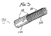
- Figure 3 is a woven tubular gasket having staple clips in accordance with the invention which provide radial rigidity to the gasket.
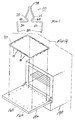
- Figure 4 illustrates woven tubular gaskets provided in accordance with the present invention for sealing the space between an oven and oven door in a self-cleaning oven.
- Figure 1 shows a clip 10 for securing a sealing member to a surface.
- clip 10 is provided with shoulder means comprising a first shoulder member, shown at 20, which interfaces the clip to the surface so that clip 10 secures the sealing member to the surface.
- the clip further comprises a first retaining member 30 integrally formed on a first side 40 of the first shoulder 20 for retaining clip 10 fixedly to the sealing member.
- the shoulder means preferably further comprises a second shoulder member 25 oppositely extended from the first shoulder member 20.
- a second retaining member 50 is integrally formed on a second side 60 of the shoulder member 25 and further fixedly retains the clip to the sealing member.
- clip 10 is adaptable for use in an oven gasket which would seal a space between an oven and an oven door.
- clip 10 is fashioned of a high temperature resistant metal material adapted to operate in the harsh environment found, for example, in a self-cleaning oven where the gasket seals the space between the oven door and the oven especially during the cleaning operation.
- Stainless steel has been found to be such a useful high temperature resistant metal.
- the head of the clip shown generally at 70, is adapted to interface through a hole in the oven door while the first and second retaining members 30 and 50 grasp the gasket, thereby securing the gasket to the oven door so that a strong and resilient seal is made between the oven and the oven door by the gasket, especially during the self-cleaning operation.
- the first and second retaining members terminate in two staple ends 80 which are integrally formed on the first and second sides of the shoulder members 40 and 60.
- the staple ends 80 are adapted to pierce the sealing member so that the clip 10 can be secured thereto.
- clip 10 is inserted through an oven gasket 90 so that the gasket can be secured to a surface.
- the staple ends 80 pierce the gasket 90 so that clip 10 securely grasps the gasket.
- Casket 90 generally comprises a sealing member which is adapted to provide a resilient seal between, for example, an oven door and an oven when the gasket is secured therebetween.
- the gasket 90 comprises a tubular braided member 100 which provides the resilient seal between the two surfaces, and a resilient tubular support member 110 which provides support to the gasket.
- the braided sealing member 100 comprises braided fiberglass which is optimally braided to provide efficient sealing
- the resilient support member comprises a knitted wire bulb adapted to provide resilient support to the gasket.
- first and second retaining members 30 and 50 terminating in the staple ends 80 are formed at angles 120 and 130 with respect to the vertical so that the staple ends of clip 10 can be efficiently crimped to the gasket after the staple ends pierce gasket 90 to be secured thereto.
- Forming the first and second retaining members 30 and 50 having staple ends 80 at angles 120 and 130, respectively, allows the retaining members to be efficiently manipulated during the staple crimping procedure. It is preferable to fashion staple ends 80 at angles 120 and 130 since clips 10 will normally be fashioned from a material having a higher flexural modulus than materials comprising common "office-type" staples.
- angles 120 and 130 provide optimum crimping and manipulation of the retaining members 30 and 50 when angles 120 and 130 are at about 3° to the normal. However, it will be recognized by those with skill in the art that if a sufficiently hard anvil surface is used to crimp the staple ends, angles 120 and 130 may be less than 3° and indeed, may approach 0°.
- FIG 2B illustrates clip 10 when retaining members 30 and 50 are preferably bent to secure the gasket 90 after the staple ends have pierced through braided tubular sleeve 100 and knitted wire bulb 110.
- retaining members 30 and 50 may only pierce the braided fiberglass sleeve 100 but not knitted wire bulb 110 and then be bent into the position shown in Figure 2B so that clip 10 can be secured to the gasket.
- retaining members 30 and 50 terminating in staple ends 80 pierce both the braided fiberglass sleeve 100 and knitted wire bulb 110 to be bent into the position shown in Figure 2B for securing the clip to the gasket 90. Either piercing arrangement and equivalents thereof are intended to be within the scope of the present invention.
- the retaining members 30 and 50 with staple ends 80 are bent back on each other as shown so that the staple ends 80 repierce the knitted wire bulb 110 at points 125.
- the staple ends then traverse through the braided fiberglass so that the retaining members or legs 30 and 50 cinch to gasket 90 at crimp angles 95, as best seen in Figure 2B, thereby fixedly retaining clip 10 to gasket 90.
- a plurality of clips 10 can be so affixed to gasket 90 and are spaced to interface with a plurality of reciprocal openings in an oven or oven door so that gasket 90 can be optimally secured thereto for sealing.
- the staple ends are crimped at crimp angles 95 so that radial rigidity is provided to the clip when it cinches to the gasket.
- radial rigidity means that the clips 10 are substantially stiff when cinched or crimped to the gasket, and are not susceptible of substantial motion outside of a plane containing the clips when they are cinched to the gasket. In this fashion the clips 10 will "stand up” on the gasket so that they are easily aligned with the spaced openings in the oven or oven door, thereby allowing the gasket to be quickly and efficiently fitted and secured to the oven.
- the crimp angles 95 are preferably arranged so that first retaining member 30 is at least 15° with respect to the front of the x-y plane 135 of clips 10 and second retaining member 50 is at least 15° with respect to the back of the x-y plane 135 of clips 10 to provide radial rigidity of the clips in the x-y plane.
- first retaining member 30 and second retaining member 50 are kept substantially parallel to each other when crimped to the gasket.
- Gaskets provided in accordance with the present invention for use during the high temperature, self-cleaning oven process are generally woven tubular gaskets such as the exemplary gasket shown in Figure 3.
- the knitted wire bulb 110 of gasket 90 is cylindrical or tubular in shape and has a first radius. Cylindrical knitted wire bulb 110 preferably provides resilient support to the gasket.
- the sealing member 100 is further preferably a cylindrical or tubular braided fiberglass sealing member having a second radius which is larger than the first radius such that the braided fiberglass sealing member 100 fits securely around the knitted wire bulb 110.
- the clips disclosed herein allow gaskets to be constructed wherein the clips may be variably spaced on the gasket according to any particularly desired arrangement for interfacing to a surface. This allows gaskets provided in accordance with the invention to have optimal clip spacing and will enhance the gasket's fit to a surface, thereby improving both performance and aesthetics.
- Woven tubular gaskets provided in accordance with the present invention are particularly useful to seal the space between ovens and oven doors as shown in Figure 4.
- Oven 140 is generally a self-cleaning oven, however gaskets described herein could easily be used to seal the space between other types of ovens and oven doors.
- the oven door 150 has holes 160 drilled therethrough such that clips 10 interface to the oven door through the holes and securely retain the gasket to the oven door so that a sealing arrangement is accomplished between the oven door 150 and the oven 140 when the oven door is closed.
- Clips 10 which are stapled through the gasket can be strategically and optimally located on the gasket to reduce the number of clips necessary to fixedly secure the gasket 90 to the oven door 150 through holes 160.
Abstract
Description
- This invention relates generally to gaskets and the attachments thereof to surfaces and substrates. More particularly, this invention relates to woven tubular gaskets having individual attachment members.
- Articles and devices for providing a sealing arrangement between two surfaces are well known. Depending upon the particular type of seal which must be achieved and the environment in which the seal will operate, particular types of gaskets and seals have been developed to accomplish adequate sealing and to ensure that the outside environment does not impinge in the area which the seal is intended to protect. To accomplish these goals, prior seals and gaskets have generally been made up of a sealing strip and an attachment mechanism that is applied to the strip to ensure that the gasket or seal will adhere to a pair of surfaces and perform the sealing function.
- Weather stripping is typical of the above-mentioned gasket arrangement for sealing a pair of surfaces. For example, weather stripping which is especially adapted for use on motor vehicles to seal the openings around doors and windows usually consists of tubular covers made of a soft material such as rubber, and a series of zigzag loops which are adapted to secure the rubber to the door or window of the car. See, e.g., U.S. Patent Nos. 2,060,353, Tea; 2,102,392, Tea; 2,121,854, Breer; and 2,121,893, Tea. The aforementioned patents generally teach a number of zigzag loops which encircle a core that is inserted through the tubular rubber covering and a fabric or panel member that covers the tubular covering to provide a unitary structure. The zigzag loops are not secured to the core, but merely slip onto the core after they are bent into a particular arrangement for insertion into the tubular member.
- Weather stripping as taught in the above patents is typically only useful for protecting the interior of a car from inclement weather conditions. Such gaskets do not provide adequate sealing in high pressure or high temperature environments, suffer the infirmity of advanced degradation of the soft tubular material which provides the seal, and therefore provide inadequate sealing once the seal ages in any significant manner. Thus, the aforementioned weather strips do not satisfy long-felt needs in the art for adequate gasket and sealing arrangements which economically and efficiently attach to a surface defining an interior structure which must be sealed.
- As can be seen from the above-referenced weather strips, it is necessary to provide an attachment mechanism to the weather strip so that it can permanently seal the surfaces. To this end, prior clips and fastening devices for use in securing rubber weather seals and gaskets to doors have been utilized. In general, these fastening devices are embedded in a material such as plastic and consist of head and leg portions which may be formed from a single piece of wire. See, e.g., U.S. Patent No. 2,643,433, Scott, at col. 3, lines 38-43. The head portion is engaged with a metal piece in the surface while the wire shank or legs are inserted through an opening in, for example, an automobile body. See Scott at col. 3, lines 55-61. Individual fasteners with wire shanks and legs may have various shapes and may connect rubber gaskets to oven doors through a flange. See, e.g., U.S. Patent No. 2,988,788, Saponara, at col. 1, lines 12-17; U.S. Patent No. 2,139,329, Fessler, at col. 1, lines 42-46.
- Other various shapes and arrangements of clips or fasteners have been devised as attachment mechanisms for gaskets. Attaching clips may be looped out of wire to be engagable with a coil spring member in a weather strip and can comprise a base divided into two portions to provide a torsional action which holds a gasket in the door of a car in a firm manner. See, e.g., U.S. Patent Nos. 3,167,824, Berwanger and 3,059,299, Sarafinas. Individual fasteners may also consist of simple bent wire clips, or more complex tabs that project upwardly and which are deformable for grabbing the periphery of a sealing member which will adhere to a surface. See U.S. Patent No. 2,867,464, Crampton and U.S. Patent No. 4,783,087, DeCore et al.
- Thus, prior attachment mechanisms for sealing weather strips and gaskets to surfaces are usually provided in multiple fashion and attach individually to a gasket so that it can be clipped to a surface which the gasket is intended to seal. However, this arrangement is extremely costly since a large number of individual fasteners must be provided to the gasket in order to effect adequate sealing of the surface and the clips are not usually optimally placed on the gasket to provide effective sealing of the gasket to the surface. Prior individual clips are therefore not economical and fail to solve a long-felt need in the art for an economic and efficient device to provide attachment of a sealing gasket to a surface.
- In efforts to ensure that sealing gaskets are adequately fastened to surfaces, prior clips have been integrally attached to springs and frames, or molded from a single piece of wire. See, e.g., U.S. Patent No. 3,167,826, Watzl et al., col. 2, lines 27-31. This type of sealing gasket may be reinforced with a sinuous wire which is bent into a zigzag corrugated shape to provide snap fastener projections which are spaced lengthwise of the sealing strip and which conform to the shape of the door which the gasket will seal. See, e.g., U.S. Patent No. 2,938,249, Milne, at col. 2, lines 28-34; U.S. Patent No. 2,579,072, Harris, at col. 3, lines 25-29.
- Similarly, prior sealing gaskets for use with oven doors may be bendable into a rectangular shape and have a wire that is simultaneously drawn through the base of the gasket while the gasket is being extruded. In such an arrangement, resilient metal clips are used to grip a base and extend to apertures to secure the gasket to the oven. See U.S. Patent No. 4,538,381, Vogel, at col. 2, lines 23-44. However, none of the aforementioned gaskets which are adapted to seal the space between surfaces provide adequate rigidity and structure to the gasket to ensure a good seal, or reduce the number of integrally formed clips to hold the gasket against one of the surfaces. Thus, the above-mentioned gaskets and seals are not economical and are difficult to implement.
- Other arrangements for sealing ovens and oven doors are disclosed in French Patent No. 2,491,120, Marchand. The Marchand patent teaches a tubular braid having a metal wire inserted therein. Connection mountings are inserted into the holes of an oven door and have curved members with a free end and a sharp border. The free end with the sharp border pierces a glass tubular fitting during the mounting process and engages the metal wire at a curved portion of the mounting. In operation of the connections disclosed in the Marchand patent, the connections are first mounted to an oven door and then pierce the tubular fitting to make connection with the wire inserted therein to cause the tubular fitting to provide a watertight seal between a watertight surface and the oven door. However, the apparatus disclosed in the Marchand patent fails to reduce the number of required clips to seal the tubular member to the door. Furthermore, the connections disclosed in the Marchand patent are not radially rigid and so are not adapted for efficient insertion into the openings. In fact, it is believed that the use of the wire insert disclosed in Marchand provides an undesirable "hinge" effect for the connections causing the connections to swivel around the wire, thereby degrading the stability of the connections, reducing the tendency of the connections to remain radially rigid in a plane containing the connections, and making it difficult to mount the gasket to a surface to be sealed. Thus, the prior weather seals, gaskets, and sealing strips described above fail to fulfill long-felt needs in the art for rigid gaskets to seal the space between two surfaces having clips which are adapted to provide an efficient interface of the gasket with a surface to be sealed.
- Woven tubular gaskets with continuous integral attachments are known to provide sealing of a space between two surfaces. See, e.g., U.S. Patent No. 4,822,060, Moyer et al. The Moyer et al. patent teaches a woven tubular gasket having a continuous integral attachment which is contained within the woven tubular gasket and which has protrusions which extend through or are extendable through the walls of the woven tubular gasket to engage openings in a substrate. See Moyer et al., col. 2, lines 9-18. The protrusions are adapted to snap into the openings of a surface and the attachment also contains zigzag portions which line up substantially perpendicular to the plane of the protrusions to provide lateral stability for the woven tubular gaskets. See Moyer et al., col. 8, lines 33-53.
- While the Moyer et al. patent teaches oven gaskets which partially solve the aforementioned long-felt needs, gaskets and clips provided in accordance with the present invention more readily solve these long-felt needs as will be understood by those with skill in the art with reference to the following detailed description read in conjunction with the accompanying drawings.
- Gaskets and sealing members provided in accordance with the present invention solve the aforementioned long-felt needs and greatly improve the efficiency and economy of producing gaskets described herein. Clips provided in accordance with the present invention may be optimally placed on the gasket, thereby reducing the number of clips required to secure the gasket to the surface and significantly reducing oven finishing time. Such results have not heretofore been achieved in the art and evince significant advantages over prior methods and devices for securing gaskets to surfaces for sealing. In a preferred embodiment, a clip for securing an oven gasket to a surface on an oven comprises shoulder means for interfacing to the surface on the oven and securing the oven gasket to the surface, first retaining means integrally formed on a first side of the shoulder means for fixedly retaining the clip to the oven gasket, and second retaining means integrally formed on a second side of the shoulder means for further fixedly retaining the clip to the oven gasket.
- Methods provided in accordance with the invention similarly produce economical oven gaskets which allow for easy and efficient installation to an oven for sealing. In a preferred embodiment, a method of manufacturing an oven gasket to seal a space between two surfaces comprises the steps of knitting a tubular bulb having a first radius to provide resilient support to the gasket, braiding a tubular resilient sealing member with a second radius greater than the first radius around the knitted bulb to provide a resilient seal between the two surfaces when the gasket is placed therebetween, piercing the braided sealing member with a plurality of clip members which will secure the gasket to one of the two surfaces, and securing the clip members to the gasket.
- With clips provided in accordance with the invention, gaskets can be constructed wherein the clips are variably spaced along the gasket. This provides the advantageous result not heretofore realized by prior gaskets of optimizing the clip spacing along the gasket to improve overall performance and aesthetics, as well as potentially reducing the required number of clips to secure the gasket to the surface. The above-referenced advantages of the invention and the solution to the long-felt needs will be better understood by the following detailed description of the invention with reference to the drawings.
- Figure 1 is a plan view of a clip provided in accordance with the present invention for securing a gasket to a surface.
- Figures 2A-2C illustrate how the clip of Figure 1 is secured to gaskets provided in accordance with the present invention.
- Figure 3 is a woven tubular gasket having staple clips in accordance with the invention which provide radial rigidity to the gasket.
- Figure 4 illustrates woven tubular gaskets provided in accordance with the present invention for sealing the space between an oven and oven door in a self-cleaning oven.
- Referring now to the drawings wherein like reference numerals refer to like elements and by way of example only without intending to limit the invention disclosed herein in any way, Figure 1 shows a
clip 10 for securing a sealing member to a surface. In a preferred embodiment,clip 10 is provided with shoulder means comprising a first shoulder member, shown at 20, which interfaces the clip to the surface so thatclip 10 secures the sealing member to the surface. The clip further comprises a first retainingmember 30 integrally formed on afirst side 40 of thefirst shoulder 20 for retainingclip 10 fixedly to the sealing member. Similarly, the shoulder means preferably further comprises asecond shoulder member 25 oppositely extended from thefirst shoulder member 20. A second retainingmember 50 is integrally formed on asecond side 60 of theshoulder member 25 and further fixedly retains the clip to the sealing member. - It will be recognized by those with skill in the art that clip 10 is adaptable for use in an oven gasket which would seal a space between an oven and an oven door. When
clip 10 is used with such an oven gasket, it is fashioned of a high temperature resistant metal material adapted to operate in the harsh environment found, for example, in a self-cleaning oven where the gasket seals the space between the oven door and the oven especially during the cleaning operation. Stainless steel has been found to be such a useful high temperature resistant metal. The head of the clip, shown generally at 70, is adapted to interface through a hole in the oven door while the first and second retainingmembers - In a further preferred embodiment, the first and second retaining members terminate in two staple ends 80 which are integrally formed on the first and second sides of the
shoulder members clip 10 can be secured thereto. Referring to Figure 2A,clip 10 is inserted through anoven gasket 90 so that the gasket can be secured to a surface. The staple ends 80 pierce thegasket 90 so thatclip 10 securely grasps the gasket.Casket 90 generally comprises a sealing member which is adapted to provide a resilient seal between, for example, an oven door and an oven when the gasket is secured therebetween. In a further preferred embodiment, thegasket 90 comprises atubular braided member 100 which provides the resilient seal between the two surfaces, and a resilienttubular support member 110 which provides support to the gasket. In still further preferred embodiments, thebraided sealing member 100 comprises braided fiberglass which is optimally braided to provide efficient sealing, and the resilient support member comprises a knitted wire bulb adapted to provide resilient support to the gasket. Such an arrangement is often described as a "woven tubular gasket" and is substantially described in the aforementioned U.S. Patent No. 4,822,060, Moyer et al., the teachings of which are specifically incorporated herein by reference. - In yet a further preferred embodiment of gasket clips provided in accordance with the present invention, first and second retaining
members clip 10 can be efficiently crimped to the gasket after the staple endspierce gasket 90 to be secured thereto. Forming the first and second retainingmembers clips 10 will normally be fashioned from a material having a higher flexural modulus than materials comprising common "office-type" staples. Thus, it is necessary to begin the deflection of the staple ends 80 at angles 120 and 130 in order to ensure adequate crimping. Additionally, the wire diameter of the stainless steel clips 10 is preferably 0.025 inches which is heavier than the diameter of common staple wire, thereby requiring a start of the deflection of the staple ends 80 in order to obtain efficient crimping. It has been determined that angles 120 and 130 provide optimum crimping and manipulation of the retainingmembers - Figure 2B illustrates
clip 10 when retainingmembers gasket 90 after the staple ends have pierced through braidedtubular sleeve 100 and knittedwire bulb 110. It will be recognized that retainingmembers fiberglass sleeve 100 but not knittedwire bulb 110 and then be bent into the position shown in Figure 2B so thatclip 10 can be secured to the gasket. It is more preferred, however, that retainingmembers fiberglass sleeve 100 and knittedwire bulb 110 to be bent into the position shown in Figure 2B for securing the clip to thegasket 90. Either piercing arrangement and equivalents thereof are intended to be within the scope of the present invention. - Referring now to Figure 2C, the retaining
members wire bulb 110 atpoints 125. Preferably, the staple ends then traverse through the braided fiberglass so that the retaining members orlegs clip 10 togasket 90. A plurality ofclips 10 can be so affixed to gasket 90 and are spaced to interface with a plurality of reciprocal openings in an oven or oven door so thatgasket 90 can be optimally secured thereto for sealing. Preferably, the staple ends are crimped at crimp angles 95 so that radial rigidity is provided to the clip when it cinches to the gasket. As used throughout this specification, the term "radial rigidity" means that theclips 10 are substantially stiff when cinched or crimped to the gasket, and are not susceptible of substantial motion outside of a plane containing the clips when they are cinched to the gasket. In this fashion theclips 10 will "stand up" on the gasket so that they are easily aligned with the spaced openings in the oven or oven door, thereby allowing the gasket to be quickly and efficiently fitted and secured to the oven. The crimp angles 95 are preferably arranged so that first retainingmember 30 is at least 15° with respect to the front of thex-y plane 135 ofclips 10 and second retainingmember 50 is at least 15° with respect to the back of thex-y plane 135 ofclips 10 to provide radial rigidity of the clips in the x-y plane. In order to achieve efficient radial rigidity of theclips 10 in the x-y plane, it is further preferred that first retainingmember 30 and second retainingmember 50 are kept substantially parallel to each other when crimped to the gasket. - Gaskets provided in accordance with the present invention for use during the high temperature, self-cleaning oven process are generally woven tubular gaskets such as the exemplary gasket shown in Figure 3. As shown in Figure 3, the knitted
wire bulb 110 ofgasket 90 is cylindrical or tubular in shape and has a first radius. Cylindricalknitted wire bulb 110 preferably provides resilient support to the gasket. The sealingmember 100 is further preferably a cylindrical or tubular braided fiberglass sealing member having a second radius which is larger than the first radius such that the braidedfiberglass sealing member 100 fits securely around the knittedwire bulb 110. - In a high temperature environment, it is advantageous to
staple clips 10 to the gasket because stapling eliminates the need for welding or cementing clips to the gasket wherein the cemented or welded seal could degrade over extended time exposure to the intense heat of the self-cleaning process in an oven. Furthermore, the clips disclosed herein allow gaskets to be constructed wherein the clips may be variably spaced on the gasket according to any particularly desired arrangement for interfacing to a surface. This allows gaskets provided in accordance with the invention to have optimal clip spacing and will enhance the gasket's fit to a surface, thereby improving both performance and aesthetics. These advantageous features and results have not heretofore been achieved, and solve long-felt needs in the art for efficient and economical oven gaskets for use in self-cleaning ovens. - Woven tubular gaskets provided in accordance with the present invention are particularly useful to seal the space between ovens and oven doors as shown in Figure 4.
Oven 140 is generally a self-cleaning oven, however gaskets described herein could easily be used to seal the space between other types of ovens and oven doors. Theoven door 150 hasholes 160 drilled therethrough such that clips 10 interface to the oven door through the holes and securely retain the gasket to the oven door so that a sealing arrangement is accomplished between theoven door 150 and theoven 140 when the oven door is closed.Clips 10 which are stapled through the gasket can be strategically and optimally located on the gasket to reduce the number of clips necessary to fixedly secure thegasket 90 to theoven door 150 throughholes 160. - In construction of self-cleaning ovens as described herein, a baked enamel surface is usually applied to the oven and oven door after the holes are drilled therethrough to finish the oven with an attractive and functional surface. However, the baked enamel inevitably
fouls holes 160 and must be cleaned from the holes before theoven gasket 90 can be fitted on the oven. With gaskets provided in accordance with the presentinvention having clips 10 strategically and optimally located on the gasket, a fewer number ofholes 160 need to be reciprocally drilled inoven door 150, thereby reducing the need to clean the baked enamel deposits inholes 160 after oven finishing and greatly improving the efficiency of the oven manufacturing process. This advantageous result has not heretofore been achieved in the oven gasket art and greatly increases the efficiency of constructing self-cleaning and other ovens. - There have thus been described certain preferred embodiments of oven gaskets for sealing the space between two surfaces. While preferred embodiments have been described and disclosed, it will be recognized by those with skill in the art that modifications are within the true spirit and scope of the invention. The appended claims are intended to cover all such modifications.
Claims (23)
- A clip for securing an oven gasket to a surface on an oven comprising:
shoulder means for interfacing to the surface on the oven and securing the oven gasket to the surface;
first retaining means integrally formed on a first side of the shoulder means for fixedly retaining the clip to the oven gasket; and
second retaining means integrally formed on a second side of the shoulder means for further fixedly retaining the clip to the oven gasket. - The clip recited in claim 1 further comprising:
first staple means formed on the first retaining means for piercing the gasket so that the clip securely grasps the gasket; and
second staple means formed on the second retaining means for piercing the gasket so that the clip further securedly grasps the gasket such that when the first and second staple means pierce the gasket the clip will fixedly secure to the gasket so that the gasket can provide a seal to the surface. - The clip recited in claim 2 wherein the first and second staple means are adapted to be crimped to the gasket at a crimp angle with respect to a plane substantially containing the clip to provide radial rigidity to the clip when the first and second staple means grasp the gasket.
- The clip recited in claim 3 wherein the crimp angle is at least 15° with respect to the plane of the clip.
- The clip recited in claim 4 wherein the first and second retaining means are formed at an angle with respect to a vertical so that the first and second staple means efficiently pierce the gasket.
- The clip recited in claim 4 wherein the angle with respect to the vertical is at 3° to the normal.
- The clip recited in claim 6 wherein the clip comprises high temperature resistant metal which is malleable such that the first and second staple means can be bent to fixedly secure the clip to the gasket.
- The clip recited in claim 7 wherein the metal is stainless steel.
- An oven gasket for sealing a space between two surfaces comprising:
tubular bulb means for providing resilient support to the gasket, the tubular bulb means having a first radius;
tubular resilient sealing means disposed around the cylindrical bulb means for providing a resilient seal between the two surfaces when the gasket is placed therebetween, the tubular resilient sealing means having a second radius larger than the first radius; and
a plurality of individual clips secured to the gasket through the tubular resilient sealing means for securing the gasket to one of the surfaces. - The gasket recited in claim 9 wherein the clips comprise:
shoulder means for interfacing with one of the two surfaces and securing the gasket to one of the two surfaces;
first retaining means integrally formed on a first side of the shoulder means for fixedly retaining the clips to the gasket; and
second retaining means integrally formed on a second side of the shoulder means for further fixedly retaining the clip to the gasket. - The gasket recited in claim 10 wherein the clips further comprise:
first staple means integrally formed on the first retaining means, the first staple means adapted to pierce the tubular resilient sealing means so that the clips securedly grasp the gasket; and
second staple means integrally formed on the second retaining means, the second staple means adapted to pierce the tubular resilient sealing means so that the clip further securedly grasps the gasket, whereby when the first and second staple means pierce the tubular resilient sealing means, the clip is fixedly secured to the gasket so that the gasket can provide a seal between the two surfaces. - The gasket recited in claim 11 wherein the first and second retaining means are formed on the shoulder means at an angle with respect to a vertical so that the clips can be efficiently manipulated to securely fasten to the gasket after the first and second staple means have pierced the tubular resilient sealing means.
- The gasket recited in claim 12 wherein the angle with respect to the vertical is at 3° normal.
- The gasket recited in claim 13 wherein the first and second staple means are crimped to the gasket at a crimp angle with respect to a plane substantially containing the clips to provide radial rigidity to the clips.
- The gasket recited in claim 14 wherein the crimp angle is at least 15° with respect to the plane of the clips.
- A method of manufacturing an oven gasket to seal a space between two surfaces comprising the steps of:
knitting a tubular bulb having a first radius to provide resilient support to the gasket;
braiding a tubular resilient sealing member with a second radius greater than the first radius around the knitted tubular bulb to provide a resilient seal between the two surfaces when the gasket is placed therebetween;
piercing the braided sealing member with a plurality of clip members which will secure the gasket to one of the two surfaces; and
securing the clip members to the gasket. - The method recited in claim 16 wherein the clip members comprise:
shoulder means for interfacing to one of the two surfaces and securing the gasket to one of the two surfaces;
first retaining means integrally formed on a first side of the shoulder means for fixedly retaining the clips to the gasket; and
second retaining means integrally formed on a second side of the shoulder means for further fixedly retaining the clips to the gasket. - The method recited in claim 17 wherein the clip members further comprise:
first staple means formed on the first retaining means for piercing the tubular sealing member so that the clip members securedly grasp the gasket; and
second staple means formed on the second retaining means for piercing the tubular sealing member so that the clip members further securedly grasp the gasket such that when the first and second staple means pierce the tubular sealing member the clip members will fixedly secure to the gasket so that the gasket can provide a seal between the two surfaces. - The method recited in claim 18 wherein the securing step comprises crimping the first and second staple means to the gasket at a crimp angle with respect to a plane containing the clip members to provide radial rigidity to the clip members.
- The method recited in claim 19 wherein the crimp angle is at least 15° with respect to the plane of the clip members.
- The method recited in claim 20 wherein the first and second retaining means are formed at an angle with respect to a vertical so that the first and second staple means efficiently pierce the tubular resilient sealing member.
- The method recited in claim 21 wherein the angle with respect to the vertical is at 3° to the normal.
- The method recited in claim 22 wherein the clip members comprise high temperature resistant metal which is malleable such that the first and second staple means can be bent to fixedly secure the clip members to the gasket.
Applications Claiming Priority (2)
| Application Number | Priority Date | Filing Date | Title |
|---|---|---|---|
| US665289 | 1991-03-06 | ||
| US07/665,289 US5205075A (en) | 1991-03-06 | 1991-03-06 | Gaskets for sealing a space between surfaces and clips for mounting gaskets to surfaces |
Publications (2)
| Publication Number | Publication Date |
|---|---|
| EP0502579A1 true EP0502579A1 (en) | 1992-09-09 |
| EP0502579B1 EP0502579B1 (en) | 1995-01-11 |
Family
ID=24669509
Family Applications (1)
| Application Number | Title | Priority Date | Filing Date |
|---|---|---|---|
| EP92200579A Expired - Lifetime EP0502579B1 (en) | 1991-03-06 | 1992-02-28 | Gaskets for sealing a space between surfaces and clips for mounting gaskets to surfaces |
Country Status (7)
| Country | Link |
|---|---|
| US (2) | US5205075A (en) |
| EP (1) | EP0502579B1 (en) |
| AT (1) | ATE117065T1 (en) |
| CA (1) | CA2062417C (en) |
| DE (1) | DE69201144T2 (en) |
| ES (1) | ES2066549T3 (en) |
| MX (1) | MX9200973A (en) |
Cited By (8)
| Publication number | Priority date | Publication date | Assignee | Title |
|---|---|---|---|---|
| WO1994023225A1 (en) * | 1993-04-05 | 1994-10-13 | T & N Plc | Braided tubular gasket with integral attachment means |
| WO1998040631A1 (en) * | 1997-03-11 | 1998-09-17 | Federal-Mogul Systems Protection Group Inc. | Tubular articles with externally installed attachment clips |
| FR2770892A1 (en) * | 1997-11-13 | 1999-05-14 | Silisol Sa | DEVICE FOR STAPLING JOINTS FOR A COOKING OVEN, AND METHOD FOR LAYING THE STAPLES |
| FR2770893A1 (en) * | 1997-11-13 | 1999-05-14 | Silisol Sa | Fastening clip for seal attached to oven door surround |
| FR2777636A1 (en) * | 1998-04-20 | 1999-10-22 | Silisol Sa | JOINT STAPLING DEVICE FOR COOKING OVENS |
| DE10153431A1 (en) * | 2001-10-30 | 2003-05-15 | Bsh Bosch Siemens Hausgeraete | Device for fastening a seal |
| FR2847325A1 (en) * | 2002-11-20 | 2004-05-21 | Davlyn Mfg Compagny Inc | FLEXIBLE THERMALLY INSULATING TUBULAR OVEN JOINTS WITH FASTENERS |
| EP2808583A1 (en) * | 2013-05-30 | 2014-12-03 | The Haigh Engineering Company Ltd | Seal apparatus and assembly method |
Families Citing this family (26)
| Publication number | Priority date | Publication date | Assignee | Title |
|---|---|---|---|---|
| US5524907A (en) * | 1994-11-03 | 1996-06-11 | Ford Motor Company | Automotive pierce-through aperture seal |
| US5706840A (en) * | 1995-03-03 | 1998-01-13 | Sandia Corporation | Precision cleaning apparatus and method |
| US5806149A (en) * | 1995-08-11 | 1998-09-15 | Davlyn Manufacturing Co., Inc. | Bent wire spring clip fasteners |
| US5915698A (en) * | 1996-07-17 | 1999-06-29 | Federal-Mogul Systems Protection Group, Inc. | Resilient wire clips with multiple pair sections and crossed ends for attaching a tubular braided gasket to an oven door having groups of clip receiving apertures at variable intervals |
| US6533289B2 (en) | 2001-06-28 | 2003-03-18 | Davlyn Manufacturing Company, Inc. | Woven tubular gaskets and gasket-like devices with spring wire fasteners for ovens |
| FR2819303A1 (en) | 2001-01-09 | 2002-07-12 | Davlyn Mfg Compagny Inc | Woven seamless tubular seal with clips for oven door has joint covered by additional woven or pleated metal tubular element |
| FR2842263B1 (en) | 2002-07-15 | 2008-07-11 | Bourgeois E | IMPLANTABLE STAPLES BY SCREWING IN A KNITTED STRUCTURE, IN PARTICULAR FOR A FURNACE JOINT, AND METHOD FOR MANUFACTURING A FURNACE JOINT EQUIPPED WITH SUCH STAPLES |
| FR2842262B1 (en) | 2002-07-15 | 2005-01-14 | Bourgeois E | IMPLANTABLE STAPLES BY SCREWING IN A KNITTED STRUCTURE, IN PARTICULAR FOR A FURNACE JOINT, AND METHOD FOR MANUFACTURING A FURNACE JOINT EQUIPPED WITH SUCH STAPLES |
| US7025359B2 (en) | 2002-08-07 | 2006-04-11 | Davlyn Manufacturing Company, Inc. | Rope gasket with termination |
| DE20314238U1 (en) * | 2002-10-01 | 2004-03-04 | Davlyn Manufacturing Co. Inc., Spring | Clip-sealing final |
| KR100484831B1 (en) * | 2002-11-28 | 2005-04-22 | 엘지전자 주식회사 | Drum washing machine |
| US6893025B2 (en) * | 2002-12-19 | 2005-05-17 | Henry C. Hight, Jr. | Gaskets and gasket-like devices including fasteners for gaskets and a method of making and using the same |
| JP4402479B2 (en) * | 2004-03-01 | 2010-01-20 | 西川ゴム工業株式会社 | Weather strip mounting structure |
| US7124540B2 (en) * | 2004-03-12 | 2006-10-24 | Mi Qiang | Sealing device |
| WO2008076581A2 (en) * | 2006-11-17 | 2008-06-26 | Davlyn International Group, Ltd. | Clip equipped, elongated flexible polymer gaskets |
| ES2325891T3 (en) * | 2007-01-12 | 2009-09-23 | RAINFOREST R&D LIMITED | CLAMP FOR USE WITH A GASKET TO SEAL A WINDOW IN THE DOOR OF A VEHICLE. |
| DE102009059205A1 (en) * | 2009-12-18 | 2011-06-22 | Miele & Cie. KG, 33332 | Sealing device for a household appliance |
| MX2011002230A (en) * | 2011-02-28 | 2012-08-31 | Mabe Sa De Cv | Oven door. |
| CN102230537B (en) * | 2011-06-14 | 2013-11-06 | 磐安县科力软管有限公司 | Dual-seal bar with fastener and panel of electric appliance |
| CN102297193A (en) * | 2011-08-12 | 2011-12-28 | 王章建 | steel wire hook |
| US20150076770A1 (en) * | 2013-09-19 | 2015-03-19 | Eaton Corporation | Insulated high temperature composite seal |
| US20150176618A1 (en) * | 2013-12-23 | 2015-06-25 | Mattson Thomas Thieme | Fastener device |
| WO2015197690A1 (en) * | 2014-06-26 | 2015-12-30 | Electrolux Appliances Aktiebolag | Domestic oven having a door with two door wings |
| CN206368878U (en) * | 2016-12-27 | 2017-08-01 | 管名豪 | A kind of fast-assembling locating button |
| US10619660B2 (en) * | 2018-02-13 | 2020-04-14 | Xuefen MAO | Clasp |
| DE202022102379U1 (en) | 2022-05-02 | 2022-05-11 | Cuylits Holding GmbH | profile seal |
Citations (3)
| Publication number | Priority date | Publication date | Assignee | Title |
|---|---|---|---|---|
| GB1197531A (en) * | 1968-06-13 | 1970-07-08 | Parkinson Cowan Appliances Ltd | Seals For Doors |
| EP0040972A1 (en) * | 1980-05-23 | 1981-12-02 | Compagnie Francaise Des Isolants | Gasket arrangement |
| EP0193364A2 (en) * | 1985-02-21 | 1986-09-03 | The Bentley-Harris Manufacturing Co. | Woven tubular gasket with continuous integral attachment means |
Family Cites Families (20)
| Publication number | Priority date | Publication date | Assignee | Title |
|---|---|---|---|---|
| US2102392A (en) * | 1936-03-27 | 1937-12-14 | Chrysler Corp | Weather strip |
| US2060353A (en) * | 1936-03-27 | 1936-11-10 | Chrysler Corp | Weather strip |
| US2121893A (en) * | 1936-03-27 | 1938-06-28 | Chrysler Corp | Weather strip |
| US2121854A (en) * | 1936-03-30 | 1938-06-28 | Chrysler Corp | Weatherstrip |
| US2139329A (en) * | 1936-04-15 | 1938-12-06 | Gen Motors Corp | Weather strip |
| FR855552A (en) * | 1939-06-01 | 1940-05-15 | Ft Products Ltd | Improvements to fixing devices |
| US2643433A (en) * | 1950-04-13 | 1953-06-30 | George E Gagnier | Fastening device |
| US2579072A (en) * | 1950-05-27 | 1951-12-18 | Gen Motors Corp | Flexible sealing strip |
| US2705355A (en) * | 1952-04-02 | 1955-04-05 | Randall E Smith | Upholstery rings |
| US2938249A (en) * | 1956-11-05 | 1960-05-31 | Gen Motors Corp | Weather strip assembly |
| US2867464A (en) * | 1957-04-19 | 1959-01-06 | Felt Products Mfg Co | Gasket mounting |
| US3059299A (en) * | 1960-02-24 | 1962-10-23 | United Carr Fastener Corp | Door pan clip |
| US2988788A (en) * | 1960-04-14 | 1961-06-20 | Saponara Domenick | Gasket |
| US3167824A (en) * | 1961-04-12 | 1965-02-02 | Hood Sponge Rubber Company | Sponge rubber weatherseal |
| US3167826A (en) * | 1962-11-26 | 1965-02-02 | Associated Spring Corp | Spring and attaching device for sealer strip |
| US3977125A (en) * | 1974-08-02 | 1976-08-31 | Nippon Oil Seal Industry Co., Ltd. | Device for sealing steel doors of coke oven |
| FR2491120A1 (en) * | 1980-09-29 | 1982-04-02 | Martin Usines Fonderie Arthur | Oven door seal clip - has resilient body which pierces seal and locates over wire attached to internal seal surface |
| US4538381A (en) * | 1983-10-11 | 1985-09-03 | Jamak, Inc. | Bendable oven door gasket |
| US4783087A (en) * | 1987-04-13 | 1988-11-08 | Fel-Pro Incorporated | Gasket assembly having a sealing insert member and method of forming |
| US4986033A (en) * | 1987-10-16 | 1991-01-22 | Davlyn Manufacturing Co., Inc. | Gaskets and gasket-like devices with fasteners |
-
1991
- 1991-03-06 US US07/665,289 patent/US5205075A/en not_active Expired - Fee Related
-
1992
- 1992-02-28 DE DE69201144T patent/DE69201144T2/en not_active Expired - Fee Related
- 1992-02-28 ES ES92200579T patent/ES2066549T3/en not_active Expired - Lifetime
- 1992-02-28 AT AT92200579T patent/ATE117065T1/en not_active IP Right Cessation
- 1992-02-28 EP EP92200579A patent/EP0502579B1/en not_active Expired - Lifetime
- 1992-03-05 MX MX9200973A patent/MX9200973A/en unknown
- 1992-03-05 CA CA002062417A patent/CA2062417C/en not_active Expired - Fee Related
-
1993
- 1993-02-04 US US08/013,705 patent/US5341601A/en not_active Expired - Fee Related
Patent Citations (3)
| Publication number | Priority date | Publication date | Assignee | Title |
|---|---|---|---|---|
| GB1197531A (en) * | 1968-06-13 | 1970-07-08 | Parkinson Cowan Appliances Ltd | Seals For Doors |
| EP0040972A1 (en) * | 1980-05-23 | 1981-12-02 | Compagnie Francaise Des Isolants | Gasket arrangement |
| EP0193364A2 (en) * | 1985-02-21 | 1986-09-03 | The Bentley-Harris Manufacturing Co. | Woven tubular gasket with continuous integral attachment means |
Cited By (11)
| Publication number | Priority date | Publication date | Assignee | Title |
|---|---|---|---|---|
| WO1994023225A1 (en) * | 1993-04-05 | 1994-10-13 | T & N Plc | Braided tubular gasket with integral attachment means |
| US5395126A (en) * | 1993-04-05 | 1995-03-07 | The Bentley-Harris Manufacturing Company | Braided tubular gasket with integral attachment means |
| WO1998040631A1 (en) * | 1997-03-11 | 1998-09-17 | Federal-Mogul Systems Protection Group Inc. | Tubular articles with externally installed attachment clips |
| FR2770892A1 (en) * | 1997-11-13 | 1999-05-14 | Silisol Sa | DEVICE FOR STAPLING JOINTS FOR A COOKING OVEN, AND METHOD FOR LAYING THE STAPLES |
| FR2770893A1 (en) * | 1997-11-13 | 1999-05-14 | Silisol Sa | Fastening clip for seal attached to oven door surround |
| EP0916898A1 (en) * | 1997-11-13 | 1999-05-19 | Silisol S.A. | Oven gasket fastening device and method for applying fasteners |
| FR2777636A1 (en) * | 1998-04-20 | 1999-10-22 | Silisol Sa | JOINT STAPLING DEVICE FOR COOKING OVENS |
| EP0952402A1 (en) * | 1998-04-20 | 1999-10-27 | Silisol S.A. | Cooking oven gasket fastening device |
| DE10153431A1 (en) * | 2001-10-30 | 2003-05-15 | Bsh Bosch Siemens Hausgeraete | Device for fastening a seal |
| FR2847325A1 (en) * | 2002-11-20 | 2004-05-21 | Davlyn Mfg Compagny Inc | FLEXIBLE THERMALLY INSULATING TUBULAR OVEN JOINTS WITH FASTENERS |
| EP2808583A1 (en) * | 2013-05-30 | 2014-12-03 | The Haigh Engineering Company Ltd | Seal apparatus and assembly method |
Also Published As
| Publication number | Publication date |
|---|---|
| CA2062417C (en) | 1999-09-28 |
| ATE117065T1 (en) | 1995-01-15 |
| MX9200973A (en) | 1992-09-01 |
| US5205075A (en) | 1993-04-27 |
| ES2066549T3 (en) | 1995-03-01 |
| DE69201144D1 (en) | 1995-02-23 |
| EP0502579B1 (en) | 1995-01-11 |
| US5341601A (en) | 1994-08-30 |
| DE69201144T2 (en) | 1995-08-24 |
| CA2062417A1 (en) | 1992-09-07 |
Similar Documents
| Publication | Publication Date | Title |
|---|---|---|
| US5205075A (en) | Gaskets for sealing a space between surfaces and clips for mounting gaskets to surfaces | |
| US5289658A (en) | Method and apparatus for providing a gasket seal between surfaces | |
| US7093838B2 (en) | Gaskets and gasket-like devices including fasteners for gaskets and a method of making and using the same | |
| EP1108899B1 (en) | Flexible retaining leg for clamping means | |
| US5918885A (en) | Tubular articles with externally installed attachment clips | |
| US7257867B2 (en) | Clip for attaching two members | |
| JPH0751986B2 (en) | Gasket | |
| EP0912863B1 (en) | Oven gasket attachment clips | |
| CA2274385C (en) | Clips for mounting gaskets to surfaces | |
| US7124540B2 (en) | Sealing device | |
| EP0040972B1 (en) | Gasket arrangement | |
| US6079402A (en) | Venturi tube mounting system | |
| EP0968678B1 (en) | Household machine with a building part couplable to a basic body | |
| US5609197A (en) | Apparatus for hanging curtains | |
| US5441226A (en) | Window mounting bracket | |
| GB1602572A (en) | Panel construction | |
| US4173047A (en) | Tubular border frame for inner spring assemblies | |
| KR0138665Y1 (en) | Car handle with hanger | |
| CZ70393A3 (en) | Method of framing glass panes, and apparatus for making the same | |
| CN2122224U (en) | Inlaid screen window frame |
Legal Events
| Date | Code | Title | Description |
|---|---|---|---|
| PUAI | Public reference made under article 153(3) epc to a published international application that has entered the european phase |
Free format text: ORIGINAL CODE: 0009012 |
|
| AK | Designated contracting states |
Kind code of ref document: A1 Designated state(s): AT BE DE ES FR GB NL |
|
| 17P | Request for examination filed |
Effective date: 19930204 |
|
| 17Q | First examination report despatched |
Effective date: 19930611 |
|
| GRAA | (expected) grant |
Free format text: ORIGINAL CODE: 0009210 |
|
| AK | Designated contracting states |
Kind code of ref document: B1 Designated state(s): AT BE DE ES FR GB NL |
|
| REF | Corresponds to: |
Ref document number: 117065 Country of ref document: AT Date of ref document: 19950115 Kind code of ref document: T |
|
| REF | Corresponds to: |
Ref document number: 69201144 Country of ref document: DE Date of ref document: 19950223 |
|
| ET | Fr: translation filed | ||
| REG | Reference to a national code |
Ref country code: ES Ref legal event code: FG2A Ref document number: 2066549 Country of ref document: ES Kind code of ref document: T3 |
|
| PLBE | No opposition filed within time limit |
Free format text: ORIGINAL CODE: 0009261 |
|
| STAA | Information on the status of an ep patent application or granted ep patent |
Free format text: STATUS: NO OPPOSITION FILED WITHIN TIME LIMIT |
|
| NLT2 | Nl: modifications (of names), taken from the european patent patent bulletin |
Owner name: THE BENTLEY-HARRIS MANUFACTURING CO. |
|
| 26N | No opposition filed | ||
| PGFP | Annual fee paid to national office [announced via postgrant information from national office to epo] |
Ref country code: NL Payment date: 20011214 Year of fee payment: 11 |
|
| REG | Reference to a national code |
Ref country code: GB Ref legal event code: IF02 |
|
| PGFP | Annual fee paid to national office [announced via postgrant information from national office to epo] |
Ref country code: AT Payment date: 20020107 Year of fee payment: 11 |
|
| PGFP | Annual fee paid to national office [announced via postgrant information from national office to epo] |
Ref country code: GB Payment date: 20020108 Year of fee payment: 11 |
|
| PGFP | Annual fee paid to national office [announced via postgrant information from national office to epo] |
Ref country code: FR Payment date: 20020131 Year of fee payment: 11 |
|
| PGFP | Annual fee paid to national office [announced via postgrant information from national office to epo] |
Ref country code: ES Payment date: 20020212 Year of fee payment: 11 |
|
| PGFP | Annual fee paid to national office [announced via postgrant information from national office to epo] |
Ref country code: DE Payment date: 20020228 Year of fee payment: 11 |
|
| PGFP | Annual fee paid to national office [announced via postgrant information from national office to epo] |
Ref country code: BE Payment date: 20020318 Year of fee payment: 11 |
|
| PG25 | Lapsed in a contracting state [announced via postgrant information from national office to epo] |
Ref country code: GB Free format text: LAPSE BECAUSE OF NON-PAYMENT OF DUE FEES Effective date: 20030228 Ref country code: BE Free format text: LAPSE BECAUSE OF NON-PAYMENT OF DUE FEES Effective date: 20030228 Ref country code: AT Free format text: LAPSE BECAUSE OF NON-PAYMENT OF DUE FEES Effective date: 20030228 |
|
| PG25 | Lapsed in a contracting state [announced via postgrant information from national office to epo] |
Ref country code: ES Free format text: LAPSE BECAUSE OF NON-PAYMENT OF DUE FEES Effective date: 20030301 |
|
| PG25 | Lapsed in a contracting state [announced via postgrant information from national office to epo] |
Ref country code: NL Free format text: LAPSE BECAUSE OF NON-PAYMENT OF DUE FEES Effective date: 20030901 |
|
| PG25 | Lapsed in a contracting state [announced via postgrant information from national office to epo] |
Ref country code: DE Free format text: LAPSE BECAUSE OF NON-PAYMENT OF DUE FEES Effective date: 20030902 |
|
| GBPC | Gb: european patent ceased through non-payment of renewal fee | ||
| PG25 | Lapsed in a contracting state [announced via postgrant information from national office to epo] |
Ref country code: FR Free format text: LAPSE BECAUSE OF NON-PAYMENT OF DUE FEES Effective date: 20031031 |
|
| NLV4 | Nl: lapsed or anulled due to non-payment of the annual fee |
Effective date: 20030901 |
|
| REG | Reference to a national code |
Ref country code: FR Ref legal event code: ST |
|
| REG | Reference to a national code |
Ref country code: ES Ref legal event code: FD2A Effective date: 20030301 |