EP0501829B1 - Récepteur digital de satellite de navigation - Google Patents
Récepteur digital de satellite de navigation Download PDFInfo
- Publication number
- EP0501829B1 EP0501829B1 EP92301741A EP92301741A EP0501829B1 EP 0501829 B1 EP0501829 B1 EP 0501829B1 EP 92301741 A EP92301741 A EP 92301741A EP 92301741 A EP92301741 A EP 92301741A EP 0501829 B1 EP0501829 B1 EP 0501829B1
- Authority
- EP
- European Patent Office
- Prior art keywords
- receiver
- code
- set forth
- search
- signal
- Prior art date
- Legal status (The legal status is an assumption and is not a legal conclusion. Google has not performed a legal analysis and makes no representation as to the accuracy of the status listed.)
- Expired - Lifetime
Links
Images


Classifications
-
- G—PHYSICS
- G01—MEASURING; TESTING
- G01S—RADIO DIRECTION-FINDING; RADIO NAVIGATION; DETERMINING DISTANCE OR VELOCITY BY USE OF RADIO WAVES; LOCATING OR PRESENCE-DETECTING BY USE OF THE REFLECTION OR RERADIATION OF RADIO WAVES; ANALOGOUS ARRANGEMENTS USING OTHER WAVES
- G01S19/00—Satellite radio beacon positioning systems; Determining position, velocity or attitude using signals transmitted by such systems
- G01S19/01—Satellite radio beacon positioning systems transmitting time-stamped messages, e.g. GPS [Global Positioning System], GLONASS [Global Orbiting Navigation Satellite System] or GALILEO
- G01S19/13—Receivers
- G01S19/32—Multimode operation in a single same satellite system, e.g. GPS L1/L2
-
- G—PHYSICS
- G01—MEASURING; TESTING
- G01S—RADIO DIRECTION-FINDING; RADIO NAVIGATION; DETERMINING DISTANCE OR VELOCITY BY USE OF RADIO WAVES; LOCATING OR PRESENCE-DETECTING BY USE OF THE REFLECTION OR RERADIATION OF RADIO WAVES; ANALOGOUS ARRANGEMENTS USING OTHER WAVES
- G01S19/00—Satellite radio beacon positioning systems; Determining position, velocity or attitude using signals transmitted by such systems
- G01S19/01—Satellite radio beacon positioning systems transmitting time-stamped messages, e.g. GPS [Global Positioning System], GLONASS [Global Orbiting Navigation Satellite System] or GALILEO
- G01S19/13—Receivers
- G01S19/21—Interference related issues ; Issues related to cross-correlation, spoofing or other methods of denial of service
-
- G—PHYSICS
- G01—MEASURING; TESTING
- G01S—RADIO DIRECTION-FINDING; RADIO NAVIGATION; DETERMINING DISTANCE OR VELOCITY BY USE OF RADIO WAVES; LOCATING OR PRESENCE-DETECTING BY USE OF THE REFLECTION OR RERADIATION OF RADIO WAVES; ANALOGOUS ARRANGEMENTS USING OTHER WAVES
- G01S19/00—Satellite radio beacon positioning systems; Determining position, velocity or attitude using signals transmitted by such systems
- G01S19/01—Satellite radio beacon positioning systems transmitting time-stamped messages, e.g. GPS [Global Positioning System], GLONASS [Global Orbiting Navigation Satellite System] or GALILEO
- G01S19/13—Receivers
- G01S19/24—Acquisition or tracking or demodulation of signals transmitted by the system
-
- G—PHYSICS
- G01—MEASURING; TESTING
- G01S—RADIO DIRECTION-FINDING; RADIO NAVIGATION; DETERMINING DISTANCE OR VELOCITY BY USE OF RADIO WAVES; LOCATING OR PRESENCE-DETECTING BY USE OF THE REFLECTION OR RERADIATION OF RADIO WAVES; ANALOGOUS ARRANGEMENTS USING OTHER WAVES
- G01S19/00—Satellite radio beacon positioning systems; Determining position, velocity or attitude using signals transmitted by such systems
- G01S19/01—Satellite radio beacon positioning systems transmitting time-stamped messages, e.g. GPS [Global Positioning System], GLONASS [Global Orbiting Navigation Satellite System] or GALILEO
- G01S19/13—Receivers
- G01S19/35—Constructional details or hardware or software details of the signal processing chain
- G01S19/37—Hardware or software details of the signal processing chain
Definitions
- This invention relates to navigation satellite receivers, and more particularly to a digital receiver having rapid signal acquisition.
- the Navstar Global Positioning System is used to determine exact geographic position (i.e., latitude, longitude and height above the earth) absolute velocity, as well as the exact time.
- the navigation device, receiver must calculate the position velocity and the time by determining distance and relative velocity to a series of satellites.
- the velocity of the receiver is calculated from the doppler frequency shift of signals transmitted from space while the exact position of the receiver is calculated from the time shift of data due to the distance the signals must travel from the satellite. This distance is called range and the doppler shift yields range rate.
- sequential tracking there is one receiver channel that sequences across multiple satellites, tracking each satellite for a predetermined period of time, and then tracking another satellite, etc. Sequential tracking requires the minimum hardware, but also has the lowest performance characteristics.
- US-4,468,793 discloses a global positioning system that utilises this concept.
- the GPS system comprises a receiver for receiving L1, L2 P-code or C/A code modulated frequency outputs.
- the receiver multiplexes the L1 and L2 signals, and code and carrier tracking loops.
- GB-A-2,155,268 discloses a receiver for a Navstar satellite navigation system.
- the receiver includes amplification and down conversion to i.f., frequencies to produce quadrature signals, Analogue-to-digital converters are provided to digitise separately the quadrature signals.
- the receiver also includes local digital code generating means, means for correlating the digitised quadrature signals separately with the same locally generated digital codes, and channel signal processing means to which the outputs of the correlation means are applied, the processing means being arranged to control the code and carrier tracking of the receiver.
- Correlation means responsive to control signals generated in the processing means are provided to effect phase rotation of the baseband signal phasor represented by the digitised quadrature signals to effect Doppler tracking in the receiver loop
- the correction means includes means for generating digital signals representing sincit and cos0t. where it is the required phase rotation angle, means for multiplying each of the quadrature signals by the sinwt and coswt signals separately and means for summing the multiplied signals according to a given algorithm.
- the present invention provides a receiver for acquiring and tracking a plurality of analog spread spectrum signals from a satellite, said analog spread spectrum signals having analog carrier signals with data and pseudo-random noise codes modulated thereon, which receiver comprising;
- the present invention also provides a receiver for acquiring and tracking each of a plurality of analog spread spectrum signals from a plurality of satellites, each analog spread spectrum signal having L1 and L2 carrier signals with data and pseudo-random noise codes modulated thereon, which receiver comprising;
- Each GPS satellite generates two spread spectrum signals centered around separate frequencies.
- the L1 channel is centered around 1575.42 megahertz, and has C/A-code, and P(Y)-code and data modulated on it.
- C/A-code has a 1.023 megahertz chipping rate with a bandwidth of about two megahertz
- P(Y)-code has a 10.23 megahertz chipping rate with a bandwidth of about 20 megahertz.
- the L2 channel is centered around 1227.6 megahertz and only has P(Y)-code and data modulated on it. Data provides information about the satellite's orbit and health and information about other satellites in the GPS constellation.
- a GPS receiver is designed having a method and system for converting the analog signal to the digital equivalent prior to processing the signal for acquisition purposes.
- a further technical advantage of our illustrated receiver is that the processing time is reduced thereby allowing for faster signal acquisition during the signal search mode.
- a still further technical advantage of our illustrated embodiment is that the part count of the GPS receiver is reduced and the system is designed using modular blocks which are interchangeable with many different types of receivers and for receivers used for different applications.
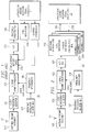
- FIGURE 1 shows prior art receiver 10 having antenna 12 which feeds into antenna preamp assembly 101. This is followed by L1/L2 frequency selector 102 and L-band down-conversion 103 which converts either the L1 signal or the L2 signal to a second IF frequency.
- the local oscillators for the down-conversion are provided by reference oscillator 107 and frequency synthesizer 108.
- the second IF (output from conversion 103) goes into analog circuit 104 for code and carrier wipe off. This is where the code transmitted by the satellite is compared and matched with the receiver's estimate of the code, and the carrier is compared with the receiver's estimate of the carrier.
- Carrier frequency changes as a function of doppler velocity between the satellite and the user, and is the way the GPS measures relative velocity.
- Code generation 109 and carrier synthesizer 110 feed the code and carrier to the code/carrier wipe off circuitry and operate under control of computer 11.
- AGC circuit 201 The output of L-band down conversion 103 is provided to analog to digital (A/D) AGC circuit 201 which is different from the A/D circuit in FIGURE 1.
- A/D circuit 201 employs a null zone Automatic Gain Control (AGC) technique which provides added immunity against jamming.
- A/D converter provides a four level output signal to signal processing circuits 202, 203 and 204. Note that circuits 202, 203 and 204 are replicas of the same chip and are detailed in concurrently filed copending patent application entitled "Method and System for a Dual Channel and Search Global Position System Signal Processor.”
- circuits 202, 203 and 204 are shown as signals 205 going to processor computer 21. They are similar to the outputs of FIGURE 1 going to processor 11 in that they represent the error between the receiver's estimate of code and carrier phase and the actual code and carrier phase being received.
- Signal 206 is the control from processor 21 back to circuits 202, 203, and 204, where the computer is directing the circuits to change their code and carrier estimates, as well as mode control of these chips.
- Modules 101, 102 and 103 contain circuitry common with that found in a good FM radio.
- circuit element 201 we have added null zone processing, which takes advantage of the spectral characteristics of the GPS signal and the spectral characteristics of the most common GPS jamming signals, which are CW signals.
- the null zone circuitry is desensitized to process CW energy, thereby yielding up to a 9dB improvement in jamming immunity against CW jammers.
- Circuit elements 202, 203 and 204 channel signal processing with no signal differentiation occurring prior to these circuit elements.
- Each element uniquely and completely generates carrier estimates, code estimates, base band predetection estimates and contains all the correlators for signal processing, and provides autonomous signal search capability for two satellites.
- Each circuit element also has the capability to simultaneously track both the C/A-code signal and the P(Y)-code signal within a single channel from a single satellite, effectively giving about a 4dB improvement in signal strength over tracking P(Y)-code only.
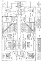
- FIGURE 3 shows a block diagram containing more detail of system 20 showing one implementation of the receiver. Note that modules 103 and 108 have been combined into a single block consisting of L-band hybrid circuit 302 and times 17 circuit 303. The exact arrangement of this circuit is dependent upon the arrangement of the various components, and this could be one circuit or multiple pieces separated and is driven by specific application requirements.
- reference oscillator 107 operates at an off beat frequency of 20.4608 megahertz or 2 x 10.2304 megahertz.
- Conventional GPS reference frequency is 10.2300 megahertz. It is the frequency offset (in this case 400 Hz) that allows us to implement digital oscillators inside channels 202, 203 and 204.
- Processor 21 is an implementation of the computer using the Intel chip set such that element 304 is an Intel 80386 and element 305 is an Intel 80387 floating point unit.
- the computer also includes static RAM 306, EPROM 308 where the program code is stored, and interface and glue logic 307.
- Glue logic provides address decode functions, interrupt control functions, direct memory access (DMA) functions, and miscellaneous housekeeping required for the computer.
- Element 31 provides the input output reference between the GPS core receiver and the rest of the world.
- Element 31 has an I/O function 309, bus drivers 310 for parallel I/O and serial drivers 311 for a serial I/O.
- FIGURES 4-4C show aspects of the null zone A to D converter (201, FIGURE 3).
- FIGURE 4A shows the functional implementation of the null zone technique with 4 bit outputs A, B, C and D.
- FIGURE 4B is a truth table for the outputs of FIGURE 4A
- FIGURE 4C shows the difference in spectral content between a gaussian wave form and a sinusoidal wave form.
- the sinusoidal wave form is what you see when a CW jammer is incoming along with the GPS signal.
- the advanced A/D conversion process shown in FIGURE 4A is a modified version of a scheme called null-zone detection and was adapted for use for two reasons:
- FIGURE 4A shows the different aspects of the A/D conversion process.
- Automatic gain control (AGC) circuit 401 maintains the raw incoming analog signal at a constant level.
- Three threshold detectors 403-405 quantize the incoming voltage into one of four values.
- the four values are assigned weights of -16, -4, +4, +16. This weighting approximates a linear detector.
- the automatic gain control (AGC) maintains the percentage of ⁇ 16 values as a constant.
- a separate detector 406 determines if the signal is, indeed, gaussian or if it has a strong CW component. The probability distribution function of these two cases is very different. If a strong CW component exists, then a waveform with equivalent power will spend a larger percentage of time near the high and low thresholds. The CW detector senses this condition, and the weights applied to the four values change to -16, -1, +1, +16. The ⁇ 1 values deemphasize signal between the high and low thresholds where less GPS signal can be extracted. The waveform straddling the high and low thresholds is rich in GPS signal and maintains full weighting.
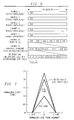
- FIGURE 5 shows the performance gain using this detector approach.
- J/S CW jammer-to-signal ratio
- the receiver employs a fast multiplexing or switching technique between the L1 and L2 signals as shown.
- both L1 and L2 enter hybrid circuit 302, but only one signal comes out. That is because the channels are capable of quickly switching between L1 code state and carrier phase and L2 code state and carrier phase. This preserves a single signal path for L1 and L2 having the effect that there is no interchannel bias between L1 and L2 and no interchannel bias between any of the channels.
- This technique also allows us to build a full function receiver with only a single RF signal path and a single A/D converter, thus eliminating at least 50 percent of the expensive RF circuitry required for a GPS receiver.
- the RF switch is a conventional switch, but this technique is made possible because channels 202, 203 and 204 are capable of switching from a single code state and carrier phase to a different code state and carrier phase very quickly unlike conventional receiver architectures.
- FIGURE 8 is a block diagram of dual channel decoder 202, which is detailed in the above-identified copending patent application entitled "Method and System for a Multi Channel and Search Global Position System Signal Processor.” The details of operation of that system will not be repeated herein.
- FIGURE 9 represents pictorially the problem inherent with determining position from a series of satellites.
- the code changes are akin to two people talking next to each other. Whatever the speaker says, the hearer receives at the exact same time. However, if the speaker were to move away far enough, the speaker would output information, and that information would arrive at the receiving person sometime later. Thus, if the speaker were reciting the alphabet, A, B, C, D in order, the receiver might be listening to the letter "A" while the sender is speaking the letter "C”.
- the code being received By knowing the delay, i.e., the number of bits different in the transmitted information, one could figure out the distance, and thus the position of the receiver along a single straight line from the sender or satellite. This repetition from three other satellites yields precise position and time of the receiver.
- noise meter 819 is tied to the ninth correlator in each channel. It has a high sampling rate tied to the discrete faner transform (DFT) samples for search. It is programmable for C/A and P(Y)-code bandwidths and is capable of aiding search by setting the thresholds in the search processor for the Tong detectors. This is done without aiding or intervention or time line requirements from the computer.
- DFT discrete faner transform
- the pre-detection integration period determines the bandwidth over which noise power is measured and is normally set to roughly match the bandwidth of the code being received. Taking absolute values provides a discriminant for the variance of I and Q.
- Post-detection integration acts as an averaging process to improve the quality of the noise power estimate.
- the noise meter can measure the power of gaussian, CW or plus noise.
- the pre-detection integration period determines the noise power bandwidth. For normal operation, the bandwidth is set to match the bandwidth of the desired code (i.e., 10 MHz for P(Y)-code and 1 MHz for C/A-code). Pre-detection integration band width is equal to: 1 pre-detection integration period
- VAR iq 0.0783321 x N + 4 (M x N) 0.5 X DATA nm
- VAR iq the variance of the I and Q integration samples
- N the pre-detection integration period
- M the number of reference clocks in the post-detection integration period
- DATA nm is the noise meter data. Note, there is a four reference clock dead time between pre-detection integration samples.
- modulating P(Y)-code onto the incoming signal prior to pre-detection integration has a negligible effect on noise meter data.
- modulating P(Y)-code onto the incoming signal prior to pre-detection integration reduces the effect CW noise has on final post-detection values.
- the noise meter is also capable of measuring CW and/or pulse noise.
- the search processor 823 will go and read the samples and apply a Tong detect algorithm to them to determine if signal is present at a particular code state and carrier frequency.
- the approximate DFT algorithm differs from the standard eight-point DFT algorithm only by the vector set that is used.
- the approximate vector set is used to reduce the circuitry required for implementation.
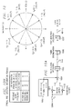
- FIGURE 12 shows the vector set, [V 0 , V 1 , V 2 , V 3 , V 4 , V 5 , V 6 , and V 7 ], used for this approximate DFT algorithm.
- This algorithm can also be expressed using the following matrix multiply equation: where Z n represents the complex value I n + jQ n .
- Z n represents the complex value I n + jQ n .
- the output level associated with each doppler bin is affected by doppler attenuation. Attenuation increases as signal offset from the internal generated carrier center frequency increases. The result is a non-linear distribution over the full range of the eight-point DFT output.
- the search processor module In addition to the seven frequency bins produced by the DFT module, the search processor module generates six frequency bins by interpolating between the seven bins generated by the DFT module. This provides a means of filling in the signal to noise ratio holes between frequency bins.
- Search processor 823 controls the DFT circuitry.
- a discrete fourier transform is performed on the I and Q data sample integration set. Frequency data from the DFT consists of seven I and Q pairs (representing seven doppler bins).
- the search processor interpolates between adjacent pairs of doppler bin data to obtain six additional doppler bins for a total of thirteen doppler bins for each of the correlators.
- a Tong detection algorithm is performed on this data to determine if a signal is present. If not, the search processor moves code to a new code state and continues the search there. The search continues until one of three conditions exist: a signal is found, the maximum search length (specified by the host processor) is reached, or an error condition occurs. Except for setup, the search processor operates independent of the resident computer.
- the seven frequency bins from the DFT are labelled B 0 , B 2 , B 4 , B 6 , B 8 , B 10 and B 12 from the most positive to the most negative doppler, respectively.
- the search processor interpolates between these frequency bins providing bins B 1 , B 3 , B 5 , B 7 , B 9 , and B 11 .
- These interpolated frequency bins indicate signal power found at a center frequency which is the arithmetic mean of the center frequencies of the even frequency bins from which it was interpolated.
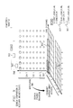
- FIGURE 14 shows gain of each DFT bin relative to the magnitude of the sample integration data.
- FIGURE 15 shows C/No loss for each doppler bin as a function of doppler. The effect of doppler attenuation is factored into the values shown on this FIGURE. Doppler attenuation is loss which occurs because the final signal IF does not exactly match the carrier generator digital oscillator frequency.
- FIGURE 16 shows the effect each stage of signal correlation has on C/No and envelope magnitude and standard deviation. These factors are useful for determining C/No loss, determining if envelopes will overflow, and for setting search threshold (V t1 ).
- the maximum envelope magnitude can be calculated as follows:
- Noise variance will have a gain of:
- 2.87 is the ratio of the standard deviation of noise of the envelope to the standard deviation of noise at the input of the PCOAC. This factor is useful for calculating search threshold, V t1 .
- V t1 and V t2 thresholds are used in the Tong detection algorithm in determining whether or not signal is present as discussed previously.
- the host processor can either set V t1 and V t2 at a fixed value or specify V t1 and V t2 to be calculated by multiplying the output of the noise meter by a specified gain (G t ).
- G t the gain
- V t1 is used for even doppler bins and V t2 (V t1 multiplied by the square root of two) for odd doppler bins.
- the noise meter's post-detection integrations are continued until all DFT input samples are collected.
- the total integration period affects the magnitude of the final noise measurement.
- V t1 is always calculated at the completion of each DFT by multiplying noise measurement by a gain value (G+) specified by the host processor or it is provided by the host processor directly.
- the search processor calculates V t2 by multiplying V t1 by the square root of two.
- FIGURE 17 A diagram of the Tong detection algorithm is shown in FIGURE 17.
- the Tong detection algorithm is designed to decide when signal is present.
- the Tong detector keeps a Tong count for each of the 104 (13 doppler bins times 8 correlators) search bins for which it is trying to determine if signal is present. Initially, the Tong count (K) is set to one 1712.
- the search processor 1703 compares each envelope 1702 to its appropriate threshold (V t1 or V t2 ). If the envelope is greater than or equal to the threshold, the Tong count for that search bin is incremented 1704. If the envelope is less than the threshold, the Tong count is decremented 1705.
- search processor may ignore the envelopes from certain correlators or for certain frequency bins.
- the search processor provides the host processor the means with which to mask the unwanted correlators or frequency bins.
- a search that is in progress can be temporarily suspended. This might be done in the event that the host processor has determined the input signal to be no good, such as when a pulse jammer is detected.
- Search suspend is tied to DFT cycles. Tong detection is not performed on DFT data which was taken during search suspend. Once suspend is de-asserted, Tong detection resumes on data from the next DFT cycle.
- Each channel has a (hardware) suspend search input.
- the host processor enables and disables the suspend input for a channel by setting a suspend input enable bit.
- the host processor can directly suspend search.
- the search processor also incorporates a hit counter which can be used by the host processor to aid in determining the adequacy of a threshold setting. It can also play a role in designs for non-gaussian environments.
- the hit counter only provides information to the host processor; it does not affect the operation of the search processor.
- the hit counter counts the number of hits for a specified number of DFT samples. It is incremented each time an active Tong count is incremented. Once the hit count is complete, it is transferred to a latch to be read by the host processor. The hit counter is cleared after the transfer to keep count of hits for the next set of DFT samples. A large hit count could be indicative of a low threshold.
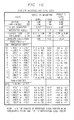
- FIGURE 18 summarizes the performance of four different receiver arcnitectures under various conditions of signal aiding and jamming levels.
- the metric used is time to first fix or the time from the point at which the receiver is turned-on until it is navigating to specified accuracy.
- P(Y) the unique receiver architecture which is P(Y) described herein produces a system that gives the best performance independent of jamming level and independent of aiding quality.
- the GPS Satellite System has in it an algorithm which converts the P(Y)-code to Y-code for special applications.
- This algorithm is not widely known. Therefore, only those receivers that have a special access to the algorithm can utilize Y-code.
- CV code In operation a special code called the CV code can be sent to the satellite, and the satellite using its special algorithm, will then convert the P(Y)-code signals to a Y-code signal.
- CV code stands for cryptovariable.
- prior receivers there has been one AOC circuit for each channel.
Landscapes
- Engineering & Computer Science (AREA)
- Radar, Positioning & Navigation (AREA)
- Remote Sensing (AREA)
- Computer Networks & Wireless Communication (AREA)
- Physics & Mathematics (AREA)
- General Physics & Mathematics (AREA)
- Position Fixing By Use Of Radio Waves (AREA)
Claims (27)
- Récepteur (20) pour acquérir et poursuivre plusieurs signaux analogiques spectre étalé, provenant d'un satellite, lesdits signaux analogiques à spectre étalé ayant des signaux de porteuse analogiques avec des données et des codes de bruit pseudo-aléatoire modulés sur ceux-ci, ledit récepteur (20) comprenant :et caractérisé en ce que ledit processeur de recherche (823) est capable de façon autonome et simultanée, de commander chacun desdits plusieurs circuits de traitement de canaux (202,203,204), chacun desdits circuits de traitement de canaux (202.203,204) étant agencé pour acquérir et poursuivre simultanément chacun desdits plusieurs signaux analogiques à spectre étalé associés audit satellite, et chacun desdits circuits de traitement de canaux (202,203,204) étant en outre capable de traiter simultanément chacun desdits codes de bruit pseudo-aléatoire associés avec lesdits signaux analogiques à spectre étalé.un circuit (103) de transposition par abaissement de fréquence pour convertir par abaissement de fréquence les signaux analogiques à spectre étalé acquis en signaux analogiques à spectre étalé convertis par abaissement de fréquence;un circuit (107,108) de génération d'un signal d'horloge local couplé audit circuit de transposition par abaissement de fréquence (103), pour engendrer une fréquence d'horloge échantillon afin de produire les signaux à spectre étalé analogiques convertis par abaissement de fréquence et pour fournir des signaux de commande pour ledit récepteur (20);un circuit d'échantillonnage (201) pour convertir les signaux analogiques à spectre étalé convertis par abaissement de fréquence en signaux numériques à spectre étalé;plusieurs circuits de traitement de canaux (202,203,204) pour démoduler les signaux numériques à spectre étalé afin d'obtenir une information de code actuel et de phase de porteuse, chaque circuit (202,203,204) de traitement de canaux engendrant un code et une phase porteuse estimés et comparant ledit code et ladite phase de porteuse estimés audit code et a ladite phase de porteuse actuels, chaque circuit de traitement de canaux (202,203,204) comprenant des corrélateurs (813) pour engendrer des données d'intégration de prédiction en réponse à ladite comparaison;un processeur de recherche (823) couplé à chacun desdits circuits de traitement de canaux (202.203,204);un processeur universel (21) pour la commande de l'ensemble du récepteur;
- Récepteur suivant la revendication 1, dans lequel chaque circuit de traitement de canaux (202,203,204) est capable d'engendrer un code et une phase de porteuse estimés et des données d'intégration de prédétection pour les signaux analogiques a spectre étalé acquis à partir de plus d'un satellite.
- Récepteur suivant la revendication 2, dans lequel chaque circuit de traitement de canaux (202,203,204) comprend des corrélateurs (813) suffisants pour engendrer des données d'intégration de prédétection en réponse à la comparaison dudit code et de ladite phase de porteuse estimés et dudit code et de ladite phase de porteuse actuels pour plus d'un satellite.
- Récepteur suivant l'une quelconque des revendications précédentes, dans lequel un seul circuit d'échantillonnage (201) est capable de distinguer à la fois, des composantes en phase (I) et en quadrature d'un signal à spectre étalé converti par abaissement de fréquence.
- Récepteur suivant l'une quelconque des revendications précédentes, dans lequel le circuit d'échantillonnage (201) engendre un signal numérique à spectre étalé à plusieurs niveaux.
- Récepteur suivant l'une quelconque des revendications précédentes, dans lequel chaque circuit de traitement de canaux est capable d'établir une poursuite de code de précision de régime permanent (code PY) et une poursuite d'un code d'acquisition grossière (CIA) simultanées.
- Récepteur suivant l'une quelconque des revendications précédentes, dans lequel le récepteur emploie une technique de multiplexage rapide entre les signaux de bande à haute fréquence (L1) et les signaux de bande à basse fréquence (L2).
- Récepteur suivant la revendication 7, dans lequel le récepteur est capable d'établir un seul trajet de signal pour les signaux de bande L1 et L2 de manière que la polarisation entre canaux entre les signaux de bande L1 et L2 et la polarisation entre les canaux est pratiquement éliminée.
- Récepteur suivant l'une quelconque des revendications précédentes, dans lequel ledit signal de porteuse analogique comprend des signaux de porteuse L1 et L2 modulés avec les données et les codes de bruit pseudo-aléatoires.
- Récepteur suivant l'une quelconque des revendications précédentes, dans lequel ledit processeur de recherche utilise un algorithme pour détection de Tong pour déterminer l'acquisition du signal à un état de code particulier pour un seuil de recherche prédéterminé.
- Récepteur suivant l'une quelconque des revendications précédentes, comprenant en outre un circuit à transformation de Fourier (824) pour engendrer des éléments binaires de fréquence (B0, B1, B2,B4,B6,B8,B10,B12) à partir desdites données d'intégration de prédétection afin d'étendre une bande de fréquence Doppler de recherche pour ledit signal analogique de porteuse.
- Récepteur suivant la revendication 11, dans lequel ledit circuit à transformation de Fourier (824) est un circuit d'approximation à transformation de Fourier discrète (824) utilisant des vecteurs complexes à deux bits.
- Récepteur suivant la revendication 11 ou la revendication 12, dans lequel ledit processeur de recherche met en oeuvre une approximation de Robenson pour engendrer des enveloppes pour chacun desdits éléments binaires de fréquence.
- Récepteur suivant l'une quelconque des revendications 1 a 13, dans lequel ledit processeur de recherche comporte un circuit pour interpoler de nouveaux éléments binaires de fréquence à partir desdits éléments binaires de fréquence provenant dudit circuit à transformation de Fourier.
- Récepteur suivant l'une quelconque des revendications 10 à 13 comprenant en outre un rnesureur de bruit (819) pour établir de façon dynamique ledit seuil de recherche.
- Récepteur suivant la revendication 15, dans lequel ledit mesureur de bruit a une largeur de bande programmable.
- Récepteur suivant la revendication 15 ou 16, dans lequel ledit processeur de recherche comporte un calculateur de seuil qui ajuste ledit seuil de recherche en réponse à un signal de sortie provenant dudit mesureur de bruit.
- Récepteur suivant l'une quelconque des revendications 15 à 17, dans lequel ledit processeur de recherche comporte en outre un second calculateur de seuil correspondant auxdits éléments binaires de fréquence à transformation de Fourier interpolés, ledit second calculateur de seuil engendrant un second seuil qui est supérieur de la racine carrée de 2 audit seuil de recherche dudit calculateur de seuil.
- Récepteur suivant l'une quelconque des revendications 15 a 18, dans lequel ledit mesureur de bruit mesure le bruit gaussien, d'ondes progressives ou d'impulsions.
- Récepteur suivant l'une quelconque des revendications 15 à 19, dans lequel ledit mesureur de bruit est programmable sur une largeur de bande de bruit pseudo-aléatoire désirée.
- Récepteur suivant l'une quelconque des revendications 10 à 20, dans lequel ledit processeur de recherche comporte un premier compteur pour limiter un nombre de passes à travers ledit algorithme de détection de Tong et force l'acquisition de signal à continuer à un nouvel état de code après qu'un certain nombre spécifique de passes, ont été réalisées audit état de code particulier.
- Récepteur suivant l'une quelconque des revendications 10 à 20, dans lequel ledit processeur de recherche comporte un premier compteur pour limiter un nombre de passe à travers ladite détection de Tong et force l'acquisition du signal à s'arrêter après qu'un nombre spécifiques de passes ont été réalisées.
- Récepteur suivant l'une quelconque des revendications 20 à 22, dans lequel ledit processeur de recherche traite plusieurs états de code simultanément.
- Récepteur suivant l'une quelconque des revendications précédentes, dans lequel ledit processeur de recherche comporte un second compteur pour contribuer à la détermination du caractère adéquat d'un seuil de recherche prédéterminé en comptant le nombre d'échantillons de signal qui excède ledit seuil de recherche prédéterminé pendant une durée de recherche donnée.
- Récepteur suivant l'une quelconque des revendications précédentes, dans lequel ledit processeur de recherche comporte un circuit pour suspendre l'acquisition de signal en réponse à une période de temps de condition connue de mauvais signal.
- Récepteur suivant l'une quelconque des revendications précédentes, dans lequel ledit circuit du processeur de recherche est intégré avec lesdits plusieurs circuits de traitement de canaux en un seul circuit monolithique.
- Récepteur suivant l'une quelconque des revendications précédentes, comprenant en outre plusieurs circuits de traitement de canaux itinérants pour démoduler lesdits signaux numériques à spectre étalé afin d'obtenir une information de code actuel et de phase de porteuse, chaque circuit de traitement de canal itinérant engendrant un code et une phase de porteuse estimés et comparant ledit code et ladite phase de porteuse estimés, audit code et a ladite phase de porteuse actuels, chaque circuit de canal itinérant parcourt un signal à bande L reçu d'une pluralité de satellites alors que chaque circuit de traitement de canal continu poursuit de façon continue l'autre signal à bande L d'un satellite spécifique; et ledit processeur universel pour commander lesdits circuits de traitement de canal continu et de canal itinérant au cours de l'acquisition et de la poursuite du signal.
Applications Claiming Priority (2)
| Application Number | Priority Date | Filing Date | Title |
|---|---|---|---|
| US07/662,585 US5347284A (en) | 1991-02-28 | 1991-02-28 | System and method for a digital navigation satellite receiver |
| US662585 | 1991-02-28 |
Publications (2)
| Publication Number | Publication Date |
|---|---|
| EP0501829A1 EP0501829A1 (fr) | 1992-09-02 |
| EP0501829B1 true EP0501829B1 (fr) | 1999-06-16 |
Family
ID=24658320
Family Applications (1)
| Application Number | Title | Priority Date | Filing Date |
|---|---|---|---|
| EP92301741A Expired - Lifetime EP0501829B1 (fr) | 1991-02-28 | 1992-02-28 | Récepteur digital de satellite de navigation |
Country Status (3)
| Country | Link |
|---|---|
| US (1) | US5347284A (fr) |
| EP (1) | EP0501829B1 (fr) |
| DE (1) | DE69229417T2 (fr) |
Cited By (4)
| Publication number | Priority date | Publication date | Assignee | Title |
|---|---|---|---|---|
| US6574558B2 (en) | 1996-04-25 | 2003-06-03 | Sirf Technology, Inc. | GPS receiver with cross-track hold |
| WO2007003049A1 (fr) * | 2005-07-05 | 2007-01-11 | Sige Semiconductor (Europe) Limited | Recepteur gps presentant une immunite accrue contre les emissions colocalisees et procede associe |
| WO2009063062A2 (fr) * | 2007-11-15 | 2009-05-22 | Qualcomm Incorporated | Récepteur gnns et circuit et système de poursuite d'un signal |
| CN112363188A (zh) * | 2020-10-13 | 2021-02-12 | 无锡卡尔曼导航技术有限公司 | 一种多分集卫星导航接收机跟踪环路方法及装置 |
Families Citing this family (118)
| Publication number | Priority date | Publication date | Assignee | Title |
|---|---|---|---|---|
| US5815525A (en) | 1991-05-13 | 1998-09-29 | Omnipoint Corporation | Multi-band, multi-mode spread-spectrum communication system |
| US5796772A (en) | 1991-05-13 | 1998-08-18 | Omnipoint Corporation | Multi-band, multi-mode spread-spectrum communication system |
| US5694414A (en) | 1991-05-13 | 1997-12-02 | Omnipoint Corporation | Multi-band, multi-mode spread-spectrum communication system |
| US5790587A (en) | 1991-05-13 | 1998-08-04 | Omnipoint Corporation | Multi-band, multi-mode spread-spectrum communication system |
| US5887020A (en) | 1991-05-13 | 1999-03-23 | Omnipoint Corporation | Multi-band, multi-mode spread-spectrum communication system |
| US5475315A (en) * | 1991-09-20 | 1995-12-12 | Audio Precision, Inc. | Method and apparatus for fast response and distortion measurement |
| USRE37408E1 (en) * | 1993-05-21 | 2001-10-16 | Trimble Navigation Ltd. | Reduction of time to first fix in an SATPS receiver |
| US5917444A (en) * | 1995-05-22 | 1999-06-29 | Trimble Navigation Ltd. | Reduction of time to first fix in an SATPS receiver |
| EP0634666A3 (fr) * | 1993-06-28 | 1997-08-20 | Victor Company Of Japan | Récepteur de réception et démodulation d'ondes GPS modulée à spectre étalé. |
| WO1995012945A1 (fr) * | 1993-11-01 | 1995-05-11 | Omnipoint Corporation | Desetalement/demodulation de signaux a spectre etale en sequence directe |
| JPH07235913A (ja) * | 1994-02-23 | 1995-09-05 | Sony Corp | スペクトラム拡散通信装置及び信号強度検出装置 |
| US5576715A (en) * | 1994-03-07 | 1996-11-19 | Leica, Inc. | Method and apparatus for digital processing in a global positioning system receiver |
| US5754584A (en) | 1994-09-09 | 1998-05-19 | Omnipoint Corporation | Non-coherent spread-spectrum continuous-phase modulation communication system |
| US5754585A (en) | 1994-09-09 | 1998-05-19 | Omnipoint Corporation | Method and apparatus for serial noncoherent correlation of a spread spectrum signal |
| US5832028A (en) | 1994-09-09 | 1998-11-03 | Omnipoint Corporation | Method and apparatus for coherent serial correlation of a spread spectrum signal |
| US5648982A (en) | 1994-09-09 | 1997-07-15 | Omnipoint Corporation | Spread spectrum transmitter |
| US5680414A (en) | 1994-09-09 | 1997-10-21 | Omnipoint Corporation | Synchronization apparatus and method for spread spectrum receiver |
| US5963586A (en) | 1994-09-09 | 1999-10-05 | Omnipoint Corporation | Method and apparatus for parallel noncoherent correlation of a spread spectrum signal |
| EP1333590A3 (fr) * | 1994-09-09 | 2004-05-12 | XIRCOM Wireless, Inc. | Corrélateur pour la réception de communications à spectre étalé et à modulation CPM |
| US5629956A (en) | 1994-09-09 | 1997-05-13 | Omnipoint Corporation | Method and apparatus for reception and noncoherent serial correlation of a continuous phase modulated signal |
| US5610940A (en) | 1994-09-09 | 1997-03-11 | Omnipoint Corporation | Method and apparatus for noncoherent reception and correlation of a continous phase modulated signal |
| US5627856A (en) | 1994-09-09 | 1997-05-06 | Omnipoint Corporation | Method and apparatus for receiving and despreading a continuous phase-modulated spread spectrum signal using self-synchronizing correlators |
| US5856998A (en) | 1994-09-09 | 1999-01-05 | Omnipoint Corporation | Method and apparatus for correlating a continuous phase modulated spread spectrum signal |
| US5881100A (en) | 1994-09-09 | 1999-03-09 | Omnipoint Corporation | Method and apparatus for coherent correlation of a spread spectrum signal |
| US5953370A (en) | 1994-09-09 | 1999-09-14 | Omnipoint Corporation | Apparatus for receiving and correlating a spread spectrum signal |
| US5757847A (en) | 1994-09-09 | 1998-05-26 | Omnipoint Corporation | Method and apparatus for decoding a phase encoded signal |
| US5659574A (en) | 1994-09-09 | 1997-08-19 | Omnipoint Corporation | Multi-bit correlation of continuous phase modulated signals |
| US5692007A (en) | 1994-09-09 | 1997-11-25 | Omnipoint Corporation | Method and apparatus for differential phase encoding and decoding in spread-spectrum communication systems with continuous-phase modulation |
| US5854813A (en) * | 1994-12-29 | 1998-12-29 | Motorola, Inc. | Multiple access up converter/modulator and method |
| US5754597A (en) * | 1994-12-29 | 1998-05-19 | Motorola, Inc. | Method and apparatus for routing a digitized RF signal to a plurality of paths |
| US5668836A (en) * | 1994-12-29 | 1997-09-16 | Motorola, Inc. | Split frequency band signal digitizer and method |
| WO1996021292A1 (fr) * | 1994-12-29 | 1996-07-11 | Motorola Inc. | Procede et dispositif de numerisation de frequences a large bande |
| US5602874A (en) * | 1994-12-29 | 1997-02-11 | Motorola, Inc. | Method and apparatus for reducing quantization noise |
| US5579341A (en) * | 1994-12-29 | 1996-11-26 | Motorola, Inc. | Multi-channel digital transceiver and method |
| US5748683A (en) * | 1994-12-29 | 1998-05-05 | Motorola, Inc. | Multi-channel transceiver having an adaptive antenna array and method |
| US5784403A (en) * | 1995-02-03 | 1998-07-21 | Omnipoint Corporation | Spread spectrum correlation using saw device |
| US5832022A (en) * | 1995-06-02 | 1998-11-03 | Omnipoint Corporation | Method and apparatus for controlling the modulation index of continuous phase modulated (CPM) signals |
| US6356607B1 (en) | 1995-06-05 | 2002-03-12 | Omnipoint Corporation | Preamble code structure and detection method and apparatus |
| US5745484A (en) * | 1995-06-05 | 1998-04-28 | Omnipoint Corporation | Efficient communication system using time division multiplexing and timing adjustment control |
| US5678169A (en) * | 1995-06-30 | 1997-10-14 | Trimble Navigation Limited | Receivers for down-conversion of L1 and L2 carrier frequency transmissions from orbiting global positioning system (GPS) satellites |
| US5710763A (en) * | 1995-07-31 | 1998-01-20 | Motorola, Inc. | Filtered fast Fourier transmultiplexer and method |
| US7092369B2 (en) | 1995-11-17 | 2006-08-15 | Symbol Technologies, Inc. | Communications network with wireless gateways for mobile terminal access |
| US6041280A (en) * | 1996-03-15 | 2000-03-21 | Sirf Technology, Inc. | GPS car navigation system |
| US5897605A (en) * | 1996-03-15 | 1999-04-27 | Sirf Technology, Inc. | Spread spectrum receiver with fast signal reacquisition |
| US6393046B1 (en) | 1996-04-25 | 2002-05-21 | Sirf Technology, Inc. | Spread spectrum receiver with multi-bit correlator |
| EP1271102B1 (fr) * | 1996-04-25 | 2012-09-05 | SiRF Technology, Inc. | Récepteur à spectre étalé à corrélateur multi-bits |
| US6018704A (en) * | 1996-04-25 | 2000-01-25 | Sirf Tech Inc | GPS receiver |
| US6047017A (en) * | 1996-04-25 | 2000-04-04 | Cahn; Charles R. | Spread spectrum receiver with multi-path cancellation |
| US6917644B2 (en) * | 1996-04-25 | 2005-07-12 | Sirf Technology, Inc. | Spread spectrum receiver with multi-path correction |
| US6198765B1 (en) | 1996-04-25 | 2001-03-06 | Sirf Technologies, Inc. | Spread spectrum receiver with multi-path correction |
| EP1209483A3 (fr) * | 1996-04-25 | 2003-03-05 | Sirf Technology, Inc. | Récepteur à spectre étalé à correlateur multi-bits |
| AU729697B2 (en) * | 1996-04-25 | 2001-02-08 | Sirf Technology, Inc. | Spread spectrum receiver with multi-bit correlator |
| US5953636A (en) * | 1996-10-30 | 1999-09-14 | Lsi Logic Corporation | Single-chip DBS receiver |
| US6141373A (en) * | 1996-11-15 | 2000-10-31 | Omnipoint Corporation | Preamble code structure and detection method and apparatus |
| US5898728A (en) * | 1996-11-22 | 1999-04-27 | Trw Inc. | Distributed analog-digital frequency dehopping system |
| US6282228B1 (en) | 1997-03-20 | 2001-08-28 | Xircom, Inc. | Spread spectrum codes for use in communication |
| US6249542B1 (en) | 1997-03-28 | 2001-06-19 | Sirf Technology, Inc. | Multipath processing for GPS receivers |
| US5983160A (en) * | 1997-04-21 | 1999-11-09 | Raytheon Company | Increase jamming immunity by optimizing processing gain for GPS/INS systems |
| US6776792B1 (en) | 1997-04-24 | 2004-08-17 | Advanced Cardiovascular Systems Inc. | Coated endovascular stent |
| US6005889A (en) * | 1997-07-17 | 1999-12-21 | Nokia | Pseudo-random noise detector for signals having a carrier frequency offset |
| GB9718131D0 (en) * | 1997-08-27 | 1997-10-29 | Sertway Limited | Communications apparatus |
| EP1674881A3 (fr) * | 1997-11-19 | 2008-04-16 | IMEC vzw | Procédé et appareil de réception de signaux GPS/GLONASS |
| US6366599B1 (en) | 1998-03-16 | 2002-04-02 | Trimble Navigation Limited | Fast acquisition of spread-spectrum signals by dynamically varying spacing of search bins |
| US6195328B1 (en) | 1998-04-15 | 2001-02-27 | The United States Of America As Represented By The Secretary Of The Air Force | Block adjustment of synchronizing signal for phase-coded signal tracking |
| WO2000028677A1 (fr) * | 1998-11-11 | 2000-05-18 | Samsung Electronics Company, Limited | Recepteur de signaux de pseudo-bruit provenant de systemes de radionavigation satellite |
| JP2002529745A (ja) | 1998-11-11 | 2002-09-10 | サムソン・エレクトロニクス・カンパニー・リミテッド | 無線航法システムの衛星信号の受信機におけるディジタル相関器 |
| US6175327B1 (en) | 1999-01-16 | 2001-01-16 | Sensors Systems, Inc. | GPS receivers with adaptive antenna systems for suppressing interference signals |
| US6137433A (en) * | 1999-03-18 | 2000-10-24 | The United States Of America As Represented By The Secretary Of Commerce | Scatterometer with adaptable spatial resolution |
| US6683923B1 (en) | 1999-04-16 | 2004-01-27 | Bd Systems, Inc. | Method and apparatus for detecting and tracking coded signals in a noisy background environment |
| US6411892B1 (en) * | 2000-07-13 | 2002-06-25 | Global Locate, Inc. | Method and apparatus for locating mobile receivers using a wide area reference network for propagating ephemeris |
| JP2003524151A (ja) * | 1999-06-17 | 2003-08-12 | サムスン エレクトロニクス カンパニー リミテッド | 個人的安全に関するシステムのための携帯式gps受信機 |
| US6166690A (en) | 1999-07-02 | 2000-12-26 | Sensor Systems, Inc. | Adaptive nulling methods for GPS reception in multiple-interference environments |
| GB9929329D0 (en) * | 1999-12-10 | 2000-02-02 | Nokia Mobile Phones Ltd | Data processing |
| US6282231B1 (en) | 1999-12-14 | 2001-08-28 | Sirf Technology, Inc. | Strong signal cancellation to enhance processing of weak spread spectrum signal |
| US6427120B1 (en) * | 2000-08-14 | 2002-07-30 | Sirf Technology, Inc. | Information transfer in a multi-mode global positioning system used with wireless networks |
| US7949362B2 (en) | 2000-05-18 | 2011-05-24 | Sirf Technology, Inc. | Satellite positioning aided communication system selection |
| US7970412B2 (en) | 2000-05-18 | 2011-06-28 | Sirf Technology, Inc. | Aided location communication system |
| US6389291B1 (en) * | 2000-08-14 | 2002-05-14 | Sirf Technology | Multi-mode global positioning system for use with wireless networks |
| US7970411B2 (en) | 2000-05-18 | 2011-06-28 | Sirf Technology, Inc. | Aided location communication system |
| US7929928B2 (en) | 2000-05-18 | 2011-04-19 | Sirf Technology Inc. | Frequency phase correction system |
| US8078189B2 (en) | 2000-08-14 | 2011-12-13 | Sirf Technology, Inc. | System and method for providing location based services over a network |
| US6462708B1 (en) | 2001-04-05 | 2002-10-08 | Sirf Technology, Inc. | GPS-based positioning system for mobile GPS terminals |
| ATE404878T1 (de) * | 2000-06-27 | 2008-08-15 | Sirf Tech Inc | Kombinierte parallele und sequenzielle detektion für die gps-signalerfassung |
| US7616705B1 (en) | 2000-07-27 | 2009-11-10 | Sirf Technology Holdings, Inc. | Monolithic GPS RF front end integrated circuit |
| US6856794B1 (en) * | 2000-07-27 | 2005-02-15 | Sirf Technology, Inc. | Monolithic GPS RF front end integrated circuit |
| US7236883B2 (en) | 2000-08-14 | 2007-06-26 | Sirf Technology, Inc. | Aiding in a satellite positioning system |
| US7197305B2 (en) | 2000-08-24 | 2007-03-27 | Sirf Technology, Inc. | Apparatus for reducing auto-correlation or cross-correlation in weak CDMA signals |
| US7680178B2 (en) | 2000-08-24 | 2010-03-16 | Sirf Technology, Inc. | Cross-correlation detection and elimination in a receiver |
| US6931233B1 (en) | 2000-08-31 | 2005-08-16 | Sirf Technology, Inc. | GPS RF front end IC with programmable frequency synthesizer for use in wireless phones |
| US7668554B2 (en) | 2001-05-21 | 2010-02-23 | Sirf Technology, Inc. | Network system for aided GPS broadcast positioning |
| US6944422B2 (en) * | 2003-04-18 | 2005-09-13 | Motorola, Inc. | Method and device for detecting an interference condition |
| US8164517B2 (en) | 2003-09-02 | 2012-04-24 | Csr Technology Inc. | Global positioning system receiver timeline management |
| US8138972B2 (en) * | 2003-09-02 | 2012-03-20 | Csr Technology Inc. | Signal processing system for satellite positioning signals |
| JP4658050B2 (ja) | 2003-09-02 | 2011-03-23 | サーフ テクノロジー インコーポレイテッド | 衛星測位信号用の信号処理システム |
| US7432853B2 (en) * | 2003-10-28 | 2008-10-07 | Trimble Navigation Limited | Ambiguity estimation of GNSS signals for three or more carriers |
| US7365680B2 (en) | 2004-02-10 | 2008-04-29 | Sirf Technology, Inc. | Location services system that reduces auto-correlation or cross-correlation in weak signals |
| US7333053B2 (en) * | 2004-04-29 | 2008-02-19 | Novariant Inc. | Signal path system and method for a ranging signal receiver |
| US7472152B1 (en) | 2004-08-02 | 2008-12-30 | The United States Of America As Represented By The Secretary Of The Air Force | Accommodating fourier transformation attenuation between transform term frequencies |
| US7551127B2 (en) * | 2005-02-10 | 2009-06-23 | Motorola, Inc. | Reconfigurable downconverter for a multi-band positioning receiver |
| US7630430B2 (en) | 2005-07-25 | 2009-12-08 | Mstar Semiconductor, Inc. | Method and apparatus for accelerating correlation processing of GPS signal |
| US7729457B2 (en) * | 2005-07-25 | 2010-06-01 | Mstar Semiconductor, Inc. | Method of weak signal acquisition and associated apparatus |
| TWI301546B (en) | 2006-06-16 | 2008-10-01 | Via Tech Inc | Global position system signal receiver and searching and acquiring method thereof |
| US8442020B1 (en) * | 2006-09-12 | 2013-05-14 | Rockwell Collins, Inc. | Phase compensation system and method to correct M-code dual sideband distortion |
| US7990315B2 (en) * | 2006-09-15 | 2011-08-02 | Mediatek Inc. | Shared memory device applied to functional stages configured in a receiver system for processing signals from different transmitter systems and method thereof |
| US8515494B2 (en) * | 2007-01-13 | 2013-08-20 | Panasonic Automotive Systems Company Of America, Division Of Panasonic Corporation Of North America | Highly configurable radio frequency (RF) module |
| US8249616B2 (en) * | 2007-08-23 | 2012-08-21 | Texas Instruments Incorporated | Satellite (GPS) assisted clock apparatus, circuits, systems and processes for cellular terminals on asynchronous networks |
| US7800536B2 (en) * | 2007-10-11 | 2010-09-21 | Mediatek, Inc. | Signal acquisition/tracking method and correlator for the same |
| EP2204914B1 (fr) * | 2008-12-30 | 2012-08-29 | u-blox AG | Procédé de traitement de signal numérique dérivé d'un signal à dispersion spectrale de séquence directe |
| DE102010004617A1 (de) * | 2010-01-13 | 2011-07-14 | Astrium GmbH, 82024 | Verbesserung der Integritätskommunikation in einem Satellitennavigationssystem |
| US8798566B2 (en) * | 2011-03-30 | 2014-08-05 | Texas Instruments Incorporated | Rapid autonomous scan in FM or other receivers with parallel search strategy, and circuits, processes and systems |
| US9778365B2 (en) | 2011-08-25 | 2017-10-03 | Bae Systems Information And Electronic Systems Integration Inc. | Single receiver GPS pointing vector sensing |
| KR101564828B1 (ko) * | 2014-01-20 | 2015-10-30 | 한국과학기술원 | 도플러 주파수가 있는 미약한 대역확산 신호의 초고속 신호 획득 및 추적을 위한 신호 처리 방법 및 그 장치 |
| CN105577230B (zh) * | 2015-12-22 | 2018-01-16 | 北京理工大学 | 收敛函数改进的Tong检测判决方法 |
| RU2616970C1 (ru) * | 2016-01-27 | 2017-04-19 | Федеральное государственное казенное военное образовательное учреждение высшего образования "Военно-космическая академия имени А.Ф. Можайского" Министерства обороны Российской Федерации | Способ обработки сигнала системы ГЛОНАСС с частотным разделением |
| US10469126B1 (en) * | 2018-09-24 | 2019-11-05 | Huawei Technologies Co., Ltd. | Code synchronization for analog spread spectrum systems |
| CN109547129B (zh) * | 2018-11-27 | 2021-09-24 | 中国科学院光电研究院 | 一种步进加权Tong检测方法 |
| CN115499036B (zh) * | 2022-11-14 | 2023-02-24 | 北京航空航天大学合肥创新研究院(北京航空航天大学合肥研究生院) | 宽带扩频信号并行捕获方法及存储介质 |
| CN117310763B (zh) * | 2023-11-30 | 2024-02-23 | 中国人民解放军国防科技大学 | 伪码调相-线性调频的时分低轨导航信号同步方法与装置 |
Family Cites Families (9)
| Publication number | Priority date | Publication date | Assignee | Title |
|---|---|---|---|---|
| US3609682A (en) * | 1969-07-16 | 1971-09-28 | Gen Electric | Augmented digital-error-correcting decoder |
| US4468793A (en) * | 1980-12-01 | 1984-08-28 | Texas Instruments Incorporated | Global position system (GPS) multiplexed receiver |
| US4578678A (en) * | 1983-11-14 | 1986-03-25 | The United States Of America As Represented By The United States National Aeronautics And Space Administration | High dynamic global positioning system receiver |
| GB2155268B (en) * | 1984-03-01 | 1987-08-26 | Standard Telephones Cables Ltd | Digital navstar receiver |
| US4701934A (en) * | 1985-09-03 | 1987-10-20 | Motorola, Inc. | Method of doppler searching in a digital GPS receiver |
| US4821294A (en) * | 1987-07-08 | 1989-04-11 | California Institute Of Technology | Digital signal processor and processing method for GPS receivers |
| US5223843A (en) * | 1988-01-05 | 1993-06-29 | Rockwell International Corporation | High performance global positioning system receiver means and method |
| US4998071A (en) * | 1988-10-25 | 1991-03-05 | Cascade Microtech, Inc. | Noise parameter test method and apparatus |
| US5101416A (en) * | 1990-11-28 | 1992-03-31 | Novatel Comunications Ltd. | Multi-channel digital receiver for global positioning system |
-
1991
- 1991-02-28 US US07/662,585 patent/US5347284A/en not_active Expired - Lifetime
-
1992
- 1992-02-28 DE DE69229417T patent/DE69229417T2/de not_active Expired - Fee Related
- 1992-02-28 EP EP92301741A patent/EP0501829B1/fr not_active Expired - Lifetime
Cited By (8)
| Publication number | Priority date | Publication date | Assignee | Title |
|---|---|---|---|---|
| US6574558B2 (en) | 1996-04-25 | 2003-06-03 | Sirf Technology, Inc. | GPS receiver with cross-track hold |
| WO2007003049A1 (fr) * | 2005-07-05 | 2007-01-11 | Sige Semiconductor (Europe) Limited | Recepteur gps presentant une immunite accrue contre les emissions colocalisees et procede associe |
| GB2441283A (en) * | 2005-07-05 | 2008-02-27 | Sige Semiconductor | GPS receiver with improved immunity to collocated transmissions and method therefor |
| GB2441283B (en) * | 2005-07-05 | 2009-06-24 | Sige Semiconductor | GPS receiver with improved immunity to collocated transmissions and method therefor |
| WO2009063062A2 (fr) * | 2007-11-15 | 2009-05-22 | Qualcomm Incorporated | Récepteur gnns et circuit et système de poursuite d'un signal |
| WO2009063062A3 (fr) * | 2007-11-15 | 2009-07-30 | Qualcomm Inc | Récepteur gnns et circuit et système de poursuite d'un signal |
| CN112363188A (zh) * | 2020-10-13 | 2021-02-12 | 无锡卡尔曼导航技术有限公司 | 一种多分集卫星导航接收机跟踪环路方法及装置 |
| CN112363188B (zh) * | 2020-10-13 | 2021-06-11 | 无锡卡尔曼导航技术有限公司 | 一种多分集卫星导航接收机跟踪环路方法及装置 |
Also Published As
| Publication number | Publication date |
|---|---|
| US5347284A (en) | 1994-09-13 |
| DE69229417D1 (de) | 1999-07-22 |
| DE69229417T2 (de) | 1999-12-30 |
| EP0501829A1 (fr) | 1992-09-02 |
Similar Documents
| Publication | Publication Date | Title |
|---|---|---|
| EP0501829B1 (fr) | Récepteur digital de satellite de navigation | |
| CA2265720C (fr) | Recepteur a rejet ameliore de signal se propageant par trajets multiples | |
| JP4408572B2 (ja) | グローバル・ポジショニング・システム信号を復調する方法及びシステム | |
| US5117232A (en) | Global system positioning receiver | |
| US5414729A (en) | Pseudorandom noise ranging receiver which compensates for multipath distortion by making use of multiple correlator time delay spacing | |
| EP1301803B1 (fr) | Detecteur de signal et procede utilisant un systeme d'accumulation coherent pour correler des segments echantillons non uniformes et disjoints | |
| CA1334110C (fr) | Recepteur de systeme de localisaton global a traitement ameliore des signaux radiofrequence et numeriques | |
| US6922546B1 (en) | GPS signal acquisition based on frequency-domain and time-domain processing | |
| US6965760B1 (en) | Satellite-based location system employing dynamic integration techniques | |
| US20060022868A1 (en) | Satellite signal reception processing apparatus and satellite signal reception processing method | |
| US6252546B1 (en) | Method and apparatus for processing multipath reflection effects in timing systems | |
| US6643320B1 (en) | Receiver for DS-CDMA signals | |
| WO2021021212A1 (fr) | Aide au signal interfréquence destiné au suivi des signaux de navigation par satellite | |
| FI109311B (fi) | Menetelmä informaatioelementin reunan määrittämiseksi, järjestelmä ja elektroniikkalaite | |
| JP2839211B2 (ja) | 広域測位システム受信機 | |
| EP1336860B1 (fr) | Récepteur GPS à haute sensibilité | |
| US7403558B2 (en) | Integrated circuit for code acquisition | |
| US7248624B2 (en) | Bit synchronization in a communications device | |
| Deshpande et al. | Analysis of the effects of GPS receiver acquisition parameters | |
| WO2009044205A2 (fr) | Corrélateur pour systèmes de navigation internationaux par satellite | |
| Weill | Theoretical and practical sensitivity limits for assisted GNSS receivers using legacy and future GNSS signals | |
| AU720886B2 (en) | Receiver with improved multipath signal rejection | |
| Backén et al. | Submitted to | |
| MacDoran et al. | Codeless GPS Applications to Multi-Path: CGAMP | |
| Ward et al. | Processor for multiple, continuous, spread spectrum signals |
Legal Events
| Date | Code | Title | Description |
|---|---|---|---|
| PUAI | Public reference made under article 153(3) epc to a published international application that has entered the european phase |
Free format text: ORIGINAL CODE: 0009012 |
|
| AK | Designated contracting states |
Kind code of ref document: A1 Designated state(s): DE FR GB IT NL |
|
| 17P | Request for examination filed |
Effective date: 19921102 |
|
| 17Q | First examination report despatched |
Effective date: 19940406 |
|
| GRAG | Despatch of communication of intention to grant |
Free format text: ORIGINAL CODE: EPIDOS AGRA |
|
| GRAG | Despatch of communication of intention to grant |
Free format text: ORIGINAL CODE: EPIDOS AGRA |
|
| GRAH | Despatch of communication of intention to grant a patent |
Free format text: ORIGINAL CODE: EPIDOS IGRA |
|
| GRAH | Despatch of communication of intention to grant a patent |
Free format text: ORIGINAL CODE: EPIDOS IGRA |
|
| GRAA | (expected) grant |
Free format text: ORIGINAL CODE: 0009210 |
|
| AK | Designated contracting states |
Kind code of ref document: B1 Designated state(s): DE FR GB IT NL |
|
| PG25 | Lapsed in a contracting state [announced via postgrant information from national office to epo] |
Ref country code: IT Free format text: LAPSE BECAUSE OF FAILURE TO SUBMIT A TRANSLATION OF THE DESCRIPTION OR TO PAY THE FEE WITHIN THE PRE;WARNING: LAPSES OF ITALIAN PATENTS WITH EFFECTIVE DATE BEFORE 2007 MAY HAVE OCCURRED AT ANY TIME BEFORE 2007. THE CORRECT EFFECTIVE DATE MAY BE DIFFERENT FROM THE ONE RECORDED.SCRIBED TIME-LIMIT Effective date: 19990616 |
|
| REF | Corresponds to: |
Ref document number: 69229417 Country of ref document: DE Date of ref document: 19990722 |
|
| ET | Fr: translation filed | ||
| PLBE | No opposition filed within time limit |
Free format text: ORIGINAL CODE: 0009261 |
|
| STAA | Information on the status of an ep patent application or granted ep patent |
Free format text: STATUS: NO OPPOSITION FILED WITHIN TIME LIMIT |
|
| 26N | No opposition filed | ||
| REG | Reference to a national code |
Ref country code: GB Ref legal event code: IF02 |
|
| PGFP | Annual fee paid to national office [announced via postgrant information from national office to epo] |
Ref country code: NL Payment date: 20090210 Year of fee payment: 18 Ref country code: DE Payment date: 20090227 Year of fee payment: 18 |
|
| PGFP | Annual fee paid to national office [announced via postgrant information from national office to epo] |
Ref country code: GB Payment date: 20090106 Year of fee payment: 18 |
|
| REG | Reference to a national code |
Ref country code: NL Ref legal event code: V1 Effective date: 20100901 |
|
| GBPC | Gb: european patent ceased through non-payment of renewal fee |
Effective date: 20100228 |
|
| REG | Reference to a national code |
Ref country code: FR Ref legal event code: ST Effective date: 20101029 |
|
| PG25 | Lapsed in a contracting state [announced via postgrant information from national office to epo] |
Ref country code: FR Free format text: LAPSE BECAUSE OF NON-PAYMENT OF DUE FEES Effective date: 20100301 Ref country code: NL Free format text: LAPSE BECAUSE OF NON-PAYMENT OF DUE FEES Effective date: 20100901 |
|
| PG25 | Lapsed in a contracting state [announced via postgrant information from national office to epo] |
Ref country code: DE Free format text: LAPSE BECAUSE OF NON-PAYMENT OF DUE FEES Effective date: 20100901 |
|
| PG25 | Lapsed in a contracting state [announced via postgrant information from national office to epo] |
Ref country code: GB Free format text: LAPSE BECAUSE OF NON-PAYMENT OF DUE FEES Effective date: 20100228 |
|
| PGFP | Annual fee paid to national office [announced via postgrant information from national office to epo] |
Ref country code: FR Payment date: 20090206 Year of fee payment: 18 |