EP0501828A1 - Vielkanal- und Suchprozessor für GPS - Google Patents
Vielkanal- und Suchprozessor für GPS Download PDFInfo
- Publication number
- EP0501828A1 EP0501828A1 EP19920301740 EP92301740A EP0501828A1 EP 0501828 A1 EP0501828 A1 EP 0501828A1 EP 19920301740 EP19920301740 EP 19920301740 EP 92301740 A EP92301740 A EP 92301740A EP 0501828 A1 EP0501828 A1 EP 0501828A1
- Authority
- EP
- European Patent Office
- Prior art keywords
- code
- set forth
- adder
- accumulator
- circuitry
- Prior art date
- Legal status (The legal status is an assumption and is not a legal conclusion. Google has not performed a legal analysis and makes no representation as to the accuracy of the status listed.)
- Granted
Links
Images


Classifications
-
- G—PHYSICS
- G01—MEASURING; TESTING
- G01S—RADIO DIRECTION-FINDING; RADIO NAVIGATION; DETERMINING DISTANCE OR VELOCITY BY USE OF RADIO WAVES; LOCATING OR PRESENCE-DETECTING BY USE OF THE REFLECTION OR RERADIATION OF RADIO WAVES; ANALOGOUS ARRANGEMENTS USING OTHER WAVES
- G01S19/00—Satellite radio beacon positioning systems; Determining position, velocity or attitude using signals transmitted by such systems
- G01S19/01—Satellite radio beacon positioning systems transmitting time-stamped messages, e.g. GPS [Global Positioning System], GLONASS [Global Orbiting Navigation Satellite System] or GALILEO
- G01S19/13—Receivers
- G01S19/24—Acquisition or tracking or demodulation of signals transmitted by the system
-
- G—PHYSICS
- G01—MEASURING; TESTING
- G01S—RADIO DIRECTION-FINDING; RADIO NAVIGATION; DETERMINING DISTANCE OR VELOCITY BY USE OF RADIO WAVES; LOCATING OR PRESENCE-DETECTING BY USE OF THE REFLECTION OR RERADIATION OF RADIO WAVES; ANALOGOUS ARRANGEMENTS USING OTHER WAVES
- G01S19/00—Satellite radio beacon positioning systems; Determining position, velocity or attitude using signals transmitted by such systems
- G01S19/01—Satellite radio beacon positioning systems transmitting time-stamped messages, e.g. GPS [Global Positioning System], GLONASS [Global Orbiting Navigation Satellite System] or GALILEO
- G01S19/13—Receivers
- G01S19/21—Interference related issues ; Issues related to cross-correlation, spoofing or other methods of denial of service
-
- G—PHYSICS
- G01—MEASURING; TESTING
- G01S—RADIO DIRECTION-FINDING; RADIO NAVIGATION; DETERMINING DISTANCE OR VELOCITY BY USE OF RADIO WAVES; LOCATING OR PRESENCE-DETECTING BY USE OF THE REFLECTION OR RERADIATION OF RADIO WAVES; ANALOGOUS ARRANGEMENTS USING OTHER WAVES
- G01S19/00—Satellite radio beacon positioning systems; Determining position, velocity or attitude using signals transmitted by such systems
- G01S19/01—Satellite radio beacon positioning systems transmitting time-stamped messages, e.g. GPS [Global Positioning System], GLONASS [Global Orbiting Navigation Satellite System] or GALILEO
- G01S19/13—Receivers
- G01S19/32—Multimode operation in a single same satellite system, e.g. GPS L1/L2
-
- G—PHYSICS
- G01—MEASURING; TESTING
- G01S—RADIO DIRECTION-FINDING; RADIO NAVIGATION; DETERMINING DISTANCE OR VELOCITY BY USE OF RADIO WAVES; LOCATING OR PRESENCE-DETECTING BY USE OF THE REFLECTION OR RERADIATION OF RADIO WAVES; ANALOGOUS ARRANGEMENTS USING OTHER WAVES
- G01S19/00—Satellite radio beacon positioning systems; Determining position, velocity or attitude using signals transmitted by such systems
- G01S19/01—Satellite radio beacon positioning systems transmitting time-stamped messages, e.g. GPS [Global Positioning System], GLONASS [Global Orbiting Navigation Satellite System] or GALILEO
- G01S19/13—Receivers
- G01S19/35—Constructional details or hardware or software details of the signal processing chain
- G01S19/37—Hardware or software details of the signal processing chain
-
- H—ELECTRICITY
- H04—ELECTRIC COMMUNICATION TECHNIQUE
- H04B—TRANSMISSION
- H04B2201/00—Indexing scheme relating to details of transmission systems not covered by a single group of H04B3/00 - H04B13/00
- H04B2201/69—Orthogonal indexing scheme relating to spread spectrum techniques in general
- H04B2201/707—Orthogonal indexing scheme relating to spread spectrum techniques in general relating to direct sequence modulation
- H04B2201/70715—Orthogonal indexing scheme relating to spread spectrum techniques in general relating to direct sequence modulation with application-specific features
Definitions
- This invention relates to global positioning signalling and more particularly to a device for achieving multi channel and search processing for a global position system.
- the Navstar Global positioning System is used to determine exact geographic position (i.e., latitude, longitude and altitude) absolute velocity as well as the exact time.
- the navigation device must calculate the position, velocity and the time by determining distance and relative velocity to a series of satellites.
- the velocity of the receiver is calculated from the doppler frequency shift of signals transmitted from the satellites. This distance is called range and the doppler shift yields range rate.
- a GPS receiver must receive signals generated from a satellite about 11,000 miles away.
- a GPS satellite transmits about a 6 watt spread spectrum signal.
- the satellite and receiver therefore, has to employ spread spectrum techniques to differentiate the signal from the noise.
- "Spread spectrum" means that the frequency or instantaneous phase of the signal being transmitted changes as a function of time.
- the receiver can track the spread spectrum signal coming from the satellite by estimating a duplicate image of the signal.
- a precise match of the satellite's spread spectrum produces a potential signal processing gain of up to 53 decibels.
- the use of spread spectrum techniques is essential to receive 6 watts of energy transmitted 11,000 miles away.
- the GPS signal is about 20 dB below ambient cosmic noise.
- Prior GPS digital receivers performed signal processing functions in the analog domain thereby requiring many expensive discrete components, some of which needed to be tuned to match the circuitry.
- a common cost/performance tradeoff was to multiplex or sequence one or two channels.
- IC While the IC presents significant benefit to a GPS receiver, it also presents several problems in building an IC that is low cost and consumes little power. Digitizing the GPS signal at the final IF requires high frequency operation for a signal processing device, i.e. 40 to 60 megahertz for a double sideband GPS signal.
- a signal processing device i.e. 40 to 60 megahertz for a double sideband GPS signal.
- Features in a GPS signal processing device which improve performance in hostile environments include full null zone signal integration, multiple correlators, anti-spoofing, and a search processor for fast acquisition.
- one technical advantage of our invention is that there is provided an adder/accumulator which supports full null zone and greatly reduces power.
- a GPS receiver circuit uses a low gate count adder/accumulator for providing a digital oscillator.
- the P-Code Channel on-a-Chip (PCOAC) of the instant invention is a dual channel GPS signal processor integrated circuit.
- a 95-pin ceramic pin-grid-array (PGA) contains the 348,300 transistor CMOS gate array.
- Major features include: two independent GPS channels; a search processor for improved acquisition time; an embedded Y-code generator: system synchronization control; and a 16-bit processor interface.
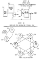
- FIGURE 1 shows a block diagram of PCOAC 10. Unused functions can be turned off allowing for a high level of power conservation in applications where power usage and/or heat dissipation is an important consideration.
- Each channel of circuit 10 is a dedicated signal processing circuit which de-modulates the code and carrier of a GPS signal and performs pre-detection integration.
- Each channel contains a code clock generator 103 (104), a P and C/A-code generator 105 (106), an L1/L2 carrier generator 109 (110), eight correlators 111, 113, 115, 117 (112, 114, 116, 118) and a noise meter 119 (120).
- Each of the eight correlators can be selected to operate with C/A-code or P-code.
- a Y-code generator 108 common to both channels provides independent Y-code for both channels.
- Search processor 123 and discrete fourier transform (DFT) function 124 improve signal acquisition capability.
- the DFT separates the sample integration data into seven frequency bins.
- Search processor 123 interpolates between these seven frequency bins to obtain six additional frequency bins, producing a total of thirteen frequency bins per correlator.
- the search processor implements a Tong detection algorithm on all eight correlators for each of the thirteen frequency bins resulting in the simultaneous search of 104 search bins per channel.
- PCOAC 10 supports three frequency plans, 57.7920 MHz, 40.9216 MHz and 40.9200 MHz operation.
- Several programmable clocks/interrupts 130 are provided to synchronize the host processor to PCOAC operation.
- Various interrupt schemes are designed to allow trade-offs to be made between system performance, processor throughput requirements and the complexity of the software.
- a standard 16-bits processor interface 131 is utilized.
- integration samples are buffered 121 (122) and the memory map is designed so that block moves are all that is required for channel updates during normal tracking operations.
- FIGURE 2 is a block diagram of the top level modules which electrically make up channel A(11) of PCOAC 10;
- Base Band Module 130 generates several global clocks for system synchronization:
- Channel Timing Module 101 generates all clocks and synchronization pulses specific to a single channel;
- Code generator Module 21 includes a programmable code clock generator, P-code and C/A-code generator/setters, and P-code and C/A-code state advance and retard for search;
- Y-Code generator Module 108 converts the P-code into Y-code for both channels simultaneously even during code state advances;
- Front-end Correlator Module 201 provides L1 or L2 carrier generation, a carrier mixer, a P-code and C/A-code delay shift register (to generate eight code phases), code mixers, data wipe-off, and noise meter signal selection;
- Intermadiate Correlator Module 202 performs the first stage of sample integration for eight complex correlators and a noise meter;
- the PCOAC samples incoming signals at greater than 40 MHz (up to 57.792 MHz depending on which frequency plan is implemented in the receiver).
- FIGURE 3 shows the most straightforward way (prior art) to implement a high precision digital oscillator, whose output is synchronous to a high speed clock.
- the circuit uses a loadable adder/accumulator 303, 304 & 305, pipelined as required. This approach was used in a single C/A-code channel or a chip previously developed.
- each digital oscillator in PCOAC 10 consumes only 43 mW on average at 57.792 MHz, saving a total of 428 mW par PCOAC or a total of 1.3 watts in a six channel receiver.
- this approach limits the output frequency of the digital oscillator to a limited range about a center frequency. The more narrow that range is, the more power that can be conserved. Also, this approach requires slightly more gates than the conventional approach (roughly 5 to 30 percent more depending on the number of bits of precision and other design specifics).
- this innovative approach is used in the PCOAC for code clock generator 103 (FIGURE 4) and carrier generator 109 (FIGURE 10).
- An approximation of a part of this approach is used for circuit simplification, causing some phase settability anomalies.
- the carrier generator generates two 2-bit outputs 90° out of phase. These 2-bits outputs cause some additional phase settability anomalies.
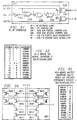
- Code clock generator 103 shown in FIGURE 4 is designed to generate a P-code clock with a nominal frequency of 10.2300 MHz. Phase and frequency of the P-code block is programmable via processor interface 131 (FIGURE 1) and bit latches 3904, 3905, 409.
- FIGURE 9 shows the frequency range, frequency settability, and phase settability for the three reference clock frequencies of PCOAC 10.
- the code clock output is generated by dividing down the reference clock by a programmable non-integer divisor. For example, in the 57.792 MHz plan, the reference clock is divided down by 5.649266862 to generate a code clock with a frequency of 10.23 MHz. To minimize power consumption, the code clock generator is designed to run a minimum of circuitry at reference clock frequency. Most of the code clock generator circuitry runs at one eighth the reference clock frequency. The benefit of low power is a tradeoff in performance in phase settability at certain frequencies.
- State machine 408 which runs at the reference clock frequency, generates the final code clock output. Averaged over time, it divides the reference clock down by the desired divisor. On each reference clock active edge, the state machine advances the phase of the code clock by a fixed member of degrees. A carry input to the state machine modifies the number of degrees the code clock is advanced on a given reference clock active edge.
- FIGURE 8 shows the number of degrees the code block phase is advanced on each reference clock and a result of each carry for each of the three frequency plans. This state machine is further illustrated in FIGURES 5, 6 & 7 for the 57.792 MHz plan, the 40.9216 MHz plan and the 40.9200 MHz plan, respectively.
- the phase advance assigned to each reference clock period and to each carry and the frequency of carries determines the average frequency of the code output.
- 32-bit adder/accumulator 3901 determines the frequency of the carry input to the state machine.
- the average frequency of the code clock output is calculated as follows: where PAref is the phase advance per reference clock and PAcarry is the phase advance per carry (see FIG 8). Solving this equation for the frequency word (FW) yields the following equation.
- Dcarry INT (8 x (1 - AW/FW)) where AW is the value of the word in the accumulator after it rolls over and Dcarry is the number of reference clocks to delay the carry.
- This approach causes a carry to occur eight reference clocks after when it would occur in a conventional adder/accumulator digital oscillator. This approach exactly matches the ideal performance of a digital oscillator with its adder/accumulator running at reference clock frequency, but uses less power because its adder/accumulator is running at one eighth the reference
- This phase bias does not degrade closed loop tracking performance. However, it may be important to consider for measuring absolute phase of a signal (for example to generate a precision time mark) or for measuring the relative phase between two signals when the difference between their doppler is significant.
- the host processor To setup initial phase of the code clock, the host processor provides the initial state of the state machine and the initial value of the thirteen most significant bits of the accumulator. The remaining nineteen bits of the accumulator are set to zero when a new code phase takes effect.
- each state represents a range of phase. Since state 1002 is the state where the clock output changes from zero to one, this state represents an average phase of zero degrees. The range of phase it represents is -30 to +30 degrees for the 57.792 MHz plan and -22.5 to +22.5 degrees for the 40.9216 and 40.9200 MHz plans.
- FIGURES 18 and 19 illustrate the phase range of each state for the 57.792 MHz plan and the 40.9216 and 40.9200 MHz plans respectively.
- the host processor provided phase word can be calculated from the following equations.
- the initial state of the state machine, S is calculated first using the following equation: where NS is the number of states in the state machine, Pcdclk is the desired code clock phase (must be positive) and S is the state that the state machine must be initialized to.
- AW is calculated using the following equation: where PAcarry is phase advance per carry (see FIGURE 8) and AW is the value the adder/accumulator must be initialized to. In this equation, eight is added to force the value of the expression to be positive before taking the modulo.
- the phase word which the host processor must write out is a function of the initial state of the state machine, S, and the initial state of the adder/accumulator, AW. the three most significant bits of the phase word determine the initial state of the state machine.
- FIGURE 8A shows the value of the three most significant bits of the phase word as a function of S for all setups. This is derived directly from FIGURES 5, 6 and 7 which show the state assignements for the state machine for each frequency plan.
- the thirteen least significant bits of the phase word determine the initial state of the thirteen most significant bits of the accumulator; the remaining accumulator bits are set to zero.
- the following equation shows the value of the thirteen least significant bits of the phase word as a function of AW:
- phase word A more direct way to calculate the phase word involves using a simple equation and then modifying the result as required. The equation is: Then the result is modified as follows:
- phase settability anomalies depending upon the frequency to which the digital oscillator is set.
- Code clock average phase is calculated based on the assumption that the average value of the adder/accumulator during a sample integration period is half the maximum value possible (a previous assumption). This is not true in all cases. Code clock phase is actually calculated using the following equation for all cases: where AA is the average value of the adder/accumulator for a sample integration period.
- the average value of the adder/accumulator for a sample integration period is a function of the frequency word and the initial state of the adder/accumulator and is calculated using the following equation: where N is the number of times the adder/accumulator is incremented in a sample integration period.
- the average adder/accumulator value is very close to 231 and is not effected by the initial adder/accumulator value (AW).
- AW initial adder/accumulator value
- certain specific frequency words cause the average adder/accumulator value to be a function of the initial adder accumulator value. When this occurs, a phase settability anormaly occurs.
- the frequency words which cause a phase settability anomaly, and the degree to which phase settability is effected can be determined as follows:
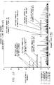
- FIGURE 14 shows the phase settability for all values of d which yield a phase settability of 2 degrees or greater.
- FIGURES 15, 16 & 17 graph these phase settability anomalies with normal code clock generator operating range super-imposed for the 57.792 MHz plan, the 40.9216 MHz plan and the 40.9200 MHz plan, respectively.
- Values of d which are not binary multiples are not strictly attainable; however, since the sample integration period is not infinite, values for d which are not a binary multiple are effectively attainable.
- carrier generator 109 creates an inphase (I) and quadrature (Q) replica of the L1 or L2 intermediate frequency (IF) carrier signal.
- the output of the carrier generator, called carrier is generated synchronous to the reference clock.
- the inphase (I) and the quadrature (Q) parts of the carrier are each two bits. Phase and frequency of the carrier is programmable via the host processor.
- FIGURE 12 shows the frequency range, frequency settability, and phase settability for the three reference clock frequencies supported by the PCOAC.
- the carrier is generated using the same principle as is used for generating the code clock.
- the state machine for the carrier generator operates using the same principle as for the code clock generator state machine. State assignments for the carrier generator are the same for all three PCOAC supported frequency plans.
- the carrier phase advances 90° per reference clock and either +45° or -45° per adder/accumulator carry.
- the 45° phase advance or retard per carry (PAcarry) is controlled by a high/low frequency control bit.
- FIGURE 11 shows the complex carrier output as a function of state. Note that the state machine generates a 2-bit number for each part of the complex carrier at each state. These two bit numbers can either be a -2, - 1, +1 or +2.
- the host processor can set a bit which hard limits the output to +1 and -1.
- the quadrature carrier lags the inphase carrier by 90 degrees.
- the adder/accumulator for the carrier generator is exactly the same as for the code clock generator.
- FCarrier Fref 360 (90 + FW 235 x PAcarry)
- Fcarrier is average frequency of the carrier
- Fref is the reference clock frequency
- FW is the 32-bit frequency word provided by the host processor
- PAcarry is the phase advance per carry (+45 or -45).
- the carry delay circuit for the carry generator is the same as it is for the code clock generator.
- the frequency depend phase bias caused by this delay circuit is calculated the same as for the code clock generator.
- Carrier phase is controlled the same way as code clock phase.
- the state machine has eight states. Each state represents a phase range of 45 degrees. State 000 represents an average phase of 22.5 degrees. The range of phase which it represents is 0 to +45 degrees. Figure 20 illustrates the phase range of each state. Assuming the average value held in the accumulator is 231 (half of the maximum value), the carrier phase is expressed by the following equation: where Pcarrier is the carrier phase, S is the state of the state machine as defined in FIGURE 11, and AW is the current content of the adder/accumulator.
- the host processor sets the initial state of the state machine and the thirteen most significant bits of the accumulator.
- the phase word can be calculated from the following equations.
- the initial state of the state machine, S is calculated first using the following equation: where Pcarrier is the desired carrier phase and S is the state that the state machine must be initialized to as defined in FIGURE 11.
- AW is calculated using the following equation: where PAcarry is the phase advance per adder/accumulator carry (-45 or +45 degrees) and AW is the value the adder/accumulator must be initialized to. In this equation, eight is added to force the value of the expression to be positive before taking the modulo.
- phase word which the host processor must write out is a function of the initial state of the state machine, S, and the initial state of the adder/accumulator, AW.
- the three most significant bits of the phase word determine the initial state of the state machine.
- the thirteen least significant bits of the phase word determine the thirteen most significant bits of the accumulator; the remaining bits of the accumulator are set to zero.
- the following equation shows the phase word as a function of S and AW:
- phase word involves using a simple equation and then modifying the result as required.
- Phase settability anomalies resulting from the carry delay circuit have been previously described. Only phase settability anomalies resulting from the unequal spacing of states will be described now.
- the carrier generator state machine has eight states. Ideally these states would be evenly spaced 45 degrees apart. Because the carrier generator has four output levels (-2, -1, +1 and +2), the states are not evenly spaced.
- FIGURE 21 shows an ideal spacing versus the actual spacing achieved with four output levels.
- four states are on one set of orthogonal axes and the other four states are on another set of orthogonal axes.
- Each set of axes has a phase bias associated with it with respect to the ideal case.
- the phase bias associated with states 0002, 0102, 1002 and 1102 is 4.065 degrees and with states 0012, 0112, 1012, and 1112 is -4.065 degrees. Note, when carrier hard-limiting is enabled, the outputs are effectively evenly spaced alleviating the cause of this phase settability anomaly.
- Frequencies which cause phase settability anomalies are ones which cause the state machine to dwell a significantly different percentage of the time on one set of orthogonal axes than on the other.
- the carrier generator state machine only changes the set of axes it is on when the adder/accumulator carries. Therefore, frequency words which cause this type of phase settability anomaly are the ones which cause the adder/accumulator to carry an even number of times every odd number clocks. For example, if the adder/accumulator carries twice every five clocks, then two out of every five clocks (40 percent of the time) the state machine will be on one set of axes and three out of every five clocks (sixty percent of the time) the state machine will be on the other set of axis.
- phase bias of +/-0.813 degrees, or a phase settability anomaly of 1.626 degrees.
- Only two frequency words cause this type of phase settability anomaly to be greater than 2 degrees.
- a frequency word of zero causes a phase settability anomaly of 4.07 degrees and a frequency word of 2/3 x 232 causes a phase settability anomaly of 2.71 degrees.
- FIGURE 22 shows all phase anomalies greater than 2 degrees for the carrier generator as a function of the frequency word. Super-imposed on this graph, is the normal operating range for the carrier generator for each mode of operation.
- This design approach can benefit any system where power conservation is important and where a high precision digital oscillator is required whose output must be synchronous to a high speed clock.
- FIGURE 29 shows a block diagram of the intermediate correlator module 202 (FIGURE 2).
- Each of the eight complex correlators per channel in the PCOAC includes four six bit adder/accumulators, two for in phase accumulation and two for quadrature accumulation.
- the adder/accumulators function in pairs, one to accumulate positive values and one to accumulate negative values.
- two adder/accumulators are required per channel to support the noise meter, making a total of 68 adder/accumulators on the chip running at up to 57.792 MHz. This makes power dissipation an issue.
- Using asynchronous design techniques one of these adder/accumulators takes less than 60 gates and dissipates less than 7 mW.
- a conventional ripple-adder with a 6-bit register takes about 90 gates and dissipates about 25 mW.
- FIGURE 23 shows the block diagram of a conventional adder/accumulator
- FIGURE 24 shows the block diagram of the specially developed adder/accumulator.
- 68 adder/accumulators this is a difference of almost 2,000 gates and, for a system with six complete L1 and L2 channels, this is a difference of about 6.8 watts. Permutation is used elsewhere in the PCOAC and is discussed later. This adder/accumulator is the most significant of many design innovations that make the PCOAC possible.
- intermediate correlator module 202 (FIGURE 2) requires the development of three custom macro-cells, which are combined to form a hard-macro function called ICORR. These three custom macro-cells are:
- the BIADD6 is a 6-bit adder/accumulator designed for low power operation and low gate utilization. It is implemented using a ripple counter 2402 with a boolean exclusive OR between each stage 2401. (FIGURE 24)
- FIGURE 25 shows a standard 6-bit ripple counter with a clear direct input.
- FIGURE 26 shows this same ripple counter with a transmission gate exclusive OR 2603, 2605, 2607, 2609, 2611 between each stage 2502, 2503, 2504, 2505, 2506, 2507 and with the input data gated with a pulse input 2601, 2602, 2604, 2606, 2608, 2610.
- FIGURE 27 shows the same function as FIGURE 26 but with the transmission gate exclusive ORs replaced with boolaan exclusive ORs, 2702 and 2708. These exclusive ORs are used to inject a pulse to any stage of the ripple counter. Boolean exclusive OR gates are required because transmission gate exclusive OR gates which are available produce a glitch which affects circuit operation.
- the content of the ripple counter is the accumulated value. When the clock input to one of the toggle flip/flops (which comprise the ripple counter) is pulsed, the value 2 n is added to the accumulated values where n (0 to 5) indicates which flip/flop input is pulsed.
- FIGURE 28 shows the final implementation of the BIADD6 macro-cell. Ripples start from either edge of an injected pulse depending upon the state of the previous flip/flop. The worst case ripple through the BIADD6 is when the BIADD6 contains a 1111102 and a 2 is added followed by adding a 32. When this occurs, the second flip/flop is clocked on the falling edge of the first injected pulse and the sixth flip/flop is clocked on the rising edge of the second injected pulse. Therefore, the BIADD6 must ripple from the second flip/flop to the last flip/flop during the pulse low time (significantly less than one reference clock period).
- negative edge clocking flip/flops are used to reduce propagation delay for a ripple and pulse injection to the last stage is delayed 2807 in order to give more time for a worst case ripple.
- a pulse generator is also used to provide a short positive going pulse, which also provides more time for the worst case ripple.
- PULGENA is a custom macro-cell designed to provide short high going pulses for the two BIADD6 cells allocated to the noise meter.
- FIGURE 31 shows the PULGENA custom cell.
- the pulse generator works by ANDing 3106 and 3107 the reference clock with a delayed and inverted version of the reference clock 3103, 3104 and 3105 and with the sign bit for the next sample of noise data.
- PULGENA has two sign inputs, one active high and the other active low. It also has an off input which forces the delayed reference clock low, thus masking the pulse outputs.
- a great deal of SPICE insulation was required to verify the width of the pulse generated is never too narrow to be missed by the BIADD6 and is always narrow engough to guarantee the worst case ripple through the BIADD6.
- PULGENB is a custom macro-cell designed to provide short high going pulses for sixteen BIADD6 cells allocated to one set of four correlators.
- FIGURE 10 shows the PULGENB custom cell.
- One pulse generator is used for all sixteen BIADD6s for power conservation.
- the PULGENB is designed using the same principle as the PULGENA.
- the BIADD6 custom cell architecture requires that only certain inputs be used, primarily binary multiple only inputs.
- FIGURE 32 lists the valid inputs for the BIADD6 in all applications.
- FIGURE 33 shows an example of how two BIADD6 cells are used together to perform the high frequency integration.
- FIGURE 37 shows inputs which are always invalid and will cause the BIADD6 to operate in a way that is unpredictable.
- FIGURE 35 shows inputs which may produce determinant results depending on the values that are already contained in the BIADD6 circuit. These input values yield determinant results when the following two criteria are met. Two adjacent bits of the adder/accumulator cannot be added to during the same reference clock period, and the bit adjacent to and less significant than a bit being added to cannot be carried into during the same reference clock period.
- the boolean logic exclusive OR must have a balanced rise and fall time and the whole adder accumulator must have time to settle between clock edges (both the rising and falling edges are active).
- FIGURE 36 shows the transistor level model of the boolean EXOR used in a previously developed experimental ASIC. Two P transistors are used in parallel to balance the N transistors. The technology used for the PCOAC has balanced P and N transistors, therefore the boolean EXOR in the PCOAC has only four P transistors.
- FIGURE 37 shows the special adder/accumulator cell developed for the PCOAC. It uses a 2-to-1 multiplexer 3702 to give the adder/accumulator two ports. Using an N-to-1 multiplexer in a similar manner would expand the operation of the adder/accumulator cell to N ports.
- FIGURE 38 shows how these cells are connected together to create a 4-bit adder/accumulator.
- delay 3802, 3803, and 3804 are added between stages 3701.
- the flip-flop 3808, 3809, 3810 are used to pipeline the carry between adder/accumulator stages.
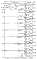
- FIGURE 39 shows a 32-bit adder/accumulator built by pipelining 4-bit adder/accumulators together.
- the most significant bit 11 of a 4-bit adder/accumulator is clocked into register 3808.
- the clock 12 used for this operation is called the carry clock.
- the bit is then clocked into another register using the opposite edge of the carry clock.
- a delayed version of the carry clock 13 clocks this bit a third time to propagate it to the carry input of the least significant bit of the next stage just after the addition at that stage has been started. It is necessary to use a delayed version of the carry clock to ensure that the carry is not injected too soon thus violating the minimum pulse width requirement of the least significant toggle flip-flop.
- This 32-bit adder/accumulator 3901 is used four times in the PCOAC, once in each code clock generator (FIGURE 4) and once in each carrier generator.
- a non-pipelined adder/accumulator uses the special adder/accumulator cell 3701 (FIGURE 37) for implementing part of the search processor circuitry 206 (FIGURE 2). This adder/accumulator configuration saves gates over a conventional adder/accumulator.
- This circuit had to be modified for two reasons. The first reason is that the circuit supports full null zone which means that the value in the chip of the demodulated signal is no longer just +1 or -1, but has multiple possible input valves. Secondly, in order to support search, we perform adjacent correlator presuming, and this removes the signal to noise ratio holes between correlators.
- FIGURE 40 shows a block diagram of the back end correlator module 203 from FIGURE 2.
- the problems previously mentioned are solved in the sample accumulators 4101 of FIGURE 41.
- the carries from the intermediate correlator module enter the sample accumulators and are immediately divided down by 8, 4107 and 4108, and are then reclocked 4109, 4110 and edge detection is performed, 4111 and 4112. Re-clocking occurs prior to edge detection in order to reduce the chance that a meta-stable state might effect a final accumulation value. From the output of the edge detector pulses are encoded 4113.
- FIGURE 42 shows the translation from carries from the intermediate correlator to which pulses are encoded.
- the pulses are encoded in such a way that a bias of 1 is added on every clock.
- the output of the pulse encoder will either be nothing, a pulse with a value of 1, or a pulse with the value of 2.
- These pulses go into a 22-bit ripple counter 4114, whose first stage uses the adder/accumulator technique previously mentioned so that a 1 or a 2 can be added.
- a separate bias accumulator 4106 is kept which keeps track of reference clocks or how many times the +1 value is added.
- a 22 bit 16:1 multiplexer 4104 selects each accumulated value and substracts the bias off using the adder 4105.
- FIGURE 43 shows the detailed circuitry required to build a sample accumulator as previously described.
- search processor previously described and also described in the above-mentioned copending patent application entitled “System and Method for a Digital Navigation Satellite Receiver” uses all correlators to search for the signal.
- FIGURE 45 shows the relative signal to noise ratio as a function of code error or how far the incoming signal is away from the signal generated in the chip at a particular correlator.
- FIGURE 46 shows the results of adjacent correlator presumming. As can be seen, there is a flat 1.25 dB loss, but there are no signal to noise ratio holes. Our sample accumulator/circuit accomplishes this, as shown in FIGURE 43, by taking the pulses encoded from the adjacent correlator and applying those values to the 22 bit accumulator 4114. In doing this, the correlator controller must clock the bias accumulator 4106 of FIGURE 41 at twice its normal rate, as noted at the bottom of FIGURE 41.
Landscapes
- Engineering & Computer Science (AREA)
- Radar, Positioning & Navigation (AREA)
- Remote Sensing (AREA)
- Computer Networks & Wireless Communication (AREA)
- Physics & Mathematics (AREA)
- General Physics & Mathematics (AREA)
- Position Fixing By Use Of Radio Waves (AREA)
Applications Claiming Priority (2)
| Application Number | Priority Date | Filing Date | Title |
|---|---|---|---|
| US66396891A | 1991-02-28 | 1991-02-28 | |
| US663968 | 2000-09-19 |
Publications (2)
| Publication Number | Publication Date |
|---|---|
| EP0501828A1 true EP0501828A1 (de) | 1992-09-02 |
| EP0501828B1 EP0501828B1 (de) | 2000-01-12 |
Family
ID=24663952
Family Applications (1)
| Application Number | Title | Priority Date | Filing Date |
|---|---|---|---|
| EP92301740A Expired - Lifetime EP0501828B1 (de) | 1991-02-28 | 1992-02-28 | Vielkanal- und Suchprozessor für GPS |
Country Status (3)
| Country | Link |
|---|---|
| US (1) | US5535237A (de) |
| EP (1) | EP0501828B1 (de) |
| DE (1) | DE69230543T2 (de) |
Cited By (9)
| Publication number | Priority date | Publication date | Assignee | Title |
|---|---|---|---|---|
| EP0600796A1 (de) * | 1992-12-04 | 1994-06-08 | Societe D'etudes Recherches Et Constructions Electroniques Sercel | Funkortungs-Verfahren und Management-System für eine Flotte von Fahrzeugen |
| WO1997040398A3 (en) * | 1996-04-25 | 1998-02-26 | Sirf Tech Inc | Spread spectrum receiver with multi-bit correlator |
| US6393046B1 (en) | 1996-04-25 | 2002-05-21 | Sirf Technology, Inc. | Spread spectrum receiver with multi-bit correlator |
| US6421609B2 (en) | 1996-04-25 | 2002-07-16 | Sirf Technology, Inc. | GPS receiver with cross-track hold |
| US6466612B2 (en) | 1997-03-28 | 2002-10-15 | Sirf Technology, Inc. | Multipath processing for GPS receivers |
| EP0924532A3 (de) * | 1997-11-19 | 2003-01-22 | IMEC vzw | Verfahren und Vorrichtung zum Empfang von GPS/GLONASS-Signalen |
| US6917644B2 (en) | 1996-04-25 | 2005-07-12 | Sirf Technology, Inc. | Spread spectrum receiver with multi-path correction |
| US7116704B2 (en) | 1999-12-14 | 2006-10-03 | Sirf Technology, Inc. | Strong signal cancellation to enhance processing of weak spread spectrum signal |
| CN103675855A (zh) * | 2013-11-29 | 2014-03-26 | 航天恒星科技有限公司 | 一种基于码周末尾时刻l1ca引导的gps-p码生成方法 |
Families Citing this family (39)
| Publication number | Priority date | Publication date | Assignee | Title |
|---|---|---|---|---|
| US6118807A (en) * | 1994-12-23 | 2000-09-12 | Intermec Ip Corp. | Methodology for received signal enhancement utilizing delay diversity processing |
| US5943363A (en) * | 1996-07-17 | 1999-08-24 | Stanford Telecommunications, Inc. | Digital spread spectrum GPS navigation receiver |
| US6192430B1 (en) * | 1997-02-28 | 2001-02-20 | Texas Instruments Incorporated | Innovative dual-channel serial interface circuit scheme |
| US6014080A (en) * | 1998-10-28 | 2000-01-11 | Pro Tech Monitoring, Inc. | Body worn active and passive tracking device |
| JP3523026B2 (ja) | 1997-09-04 | 2004-04-26 | 三菱電機株式会社 | 画像信号処理装置 |
| JPH11142501A (ja) * | 1997-11-13 | 1999-05-28 | Sokkia Co Ltd | Gps受信機 |
| US6323805B1 (en) * | 1998-09-09 | 2001-11-27 | Qualcomm, Inc. | Data boundary aware base station assisted position location |
| US6137433A (en) * | 1999-03-18 | 2000-10-24 | The United States Of America As Represented By The Secretary Of Commerce | Scatterometer with adaptable spatial resolution |
| US6683923B1 (en) | 1999-04-16 | 2004-01-27 | Bd Systems, Inc. | Method and apparatus for detecting and tracking coded signals in a noisy background environment |
| US6441601B1 (en) * | 1999-11-12 | 2002-08-27 | Itt Manufacturing Enterprises, Inc. | Phase meter using a permuter |
| US6252545B1 (en) * | 2000-02-04 | 2001-06-26 | Lucent Technologies Inc. | Enhancement of signal-detection capability of GPS systems |
| US7184461B2 (en) * | 2000-03-13 | 2007-02-27 | Pri Research & Development Corp. | High speed precision pseudo random noise shift control for fast multiple channel global positioning system signal re-tracking |
| US7173957B2 (en) * | 2000-03-13 | 2007-02-06 | Pri Research & Development Corp. | Efficient epoch processing in multichannel global positioning system signal receiver |
| US6965631B2 (en) * | 2000-03-13 | 2005-11-15 | Pri Research & Development Corp. | Low power passive correlators for multichannel global positioning system signal receiver |
| US6369753B1 (en) * | 2000-08-22 | 2002-04-09 | Motorola, Inc. | Host-independent monolithic integrated circuit for RF downconversion and digital signal processing of GPS signals |
| US7180970B1 (en) * | 2001-03-02 | 2007-02-20 | Southwest Research Institute | Automatic link establishment using external synchronization |
| US6947880B2 (en) * | 2002-04-23 | 2005-09-20 | Motorola, Inc. | Method for improving accuracy of a velocity model |
| FR2843638B1 (fr) * | 2002-08-13 | 2004-10-22 | Thales Sa | Recepteur de positionnement par satellite avec correction d'erreurs d'inter-correlation |
| US7197089B2 (en) * | 2002-08-30 | 2007-03-27 | Rf Micro Devices, Inc. | Frequency plan for GPS receiver |
| US20040043745A1 (en) * | 2002-08-30 | 2004-03-04 | Richard Najarian | Integrated GPS receiver architecture |
| US7099406B2 (en) * | 2002-08-30 | 2006-08-29 | Rf Micro Devices, Inc. | Alias sampling for IF-to-baseband conversion in a GPS receiver |
| US7463189B2 (en) * | 2002-10-04 | 2008-12-09 | Signav Pty Ltd. | Satellite-based positioning system improvement |
| US7065629B2 (en) * | 2002-11-18 | 2006-06-20 | Rf Micro Devices, Inc. | Address translation logic for use in a GPS receiver |
| US6778135B2 (en) * | 2002-11-18 | 2004-08-17 | Rf Micro Devices, Inc. | GPS Receiver |
| US6806827B2 (en) * | 2002-11-18 | 2004-10-19 | Rf Micro Devices, Inc. | Using FFT engines to process decorrelated GPS signals to establish frequencies of received signals |
| US20040095272A1 (en) * | 2002-11-18 | 2004-05-20 | Rf Micro Devices, Inc. | Saving power in a GPS receiver by controlling domain clocking |
| US6825802B2 (en) * | 2002-11-18 | 2004-11-30 | Andreas Warloe | Avoiding interference to a GPS receiver from wireless transmissions by time multiplexing GPS reception |
| US7551132B2 (en) * | 2004-07-02 | 2009-06-23 | Nemerix Sa | GPS receiver with fast acquisition time |
| WO2006003673A1 (en) * | 2004-07-05 | 2006-01-12 | Accord Software & Systems Pvt. Ltd. | Low gate count sequential multitap correlator |
| EP1688755A1 (de) * | 2005-02-04 | 2006-08-09 | Nemerix SA | Vermeidung von Verlusten in Zwischenfrequenzen bei der FFT in GPS Empfängern |
| US7428259B2 (en) * | 2005-05-06 | 2008-09-23 | Sirf Technology Holdings, Inc. | Efficient and flexible GPS receiver baseband architecture |
| US7630430B2 (en) | 2005-07-25 | 2009-12-08 | Mstar Semiconductor, Inc. | Method and apparatus for accelerating correlation processing of GPS signal |
| US7729457B2 (en) * | 2005-07-25 | 2010-06-01 | Mstar Semiconductor, Inc. | Method of weak signal acquisition and associated apparatus |
| US7477674B2 (en) * | 2005-11-14 | 2009-01-13 | The Boeing Company | High-gain solid-state laser |
| US7671796B2 (en) * | 2006-03-28 | 2010-03-02 | Mediatek Inc. | Satellite search method |
| US7612714B2 (en) * | 2006-03-28 | 2009-11-03 | Mediatek Inc. | Satellite search method |
| US8249616B2 (en) * | 2007-08-23 | 2012-08-21 | Texas Instruments Incorporated | Satellite (GPS) assisted clock apparatus, circuits, systems and processes for cellular terminals on asynchronous networks |
| KR101564828B1 (ko) * | 2014-01-20 | 2015-10-30 | 한국과학기술원 | 도플러 주파수가 있는 미약한 대역확산 신호의 초고속 신호 획득 및 추적을 위한 신호 처리 방법 및 그 장치 |
| US9899798B2 (en) | 2015-08-03 | 2018-02-20 | University Of Central Florida Research Foundation, Inc. | Apparatus and method for suppressing parasitic lasing and applications thereof |
Citations (2)
| Publication number | Priority date | Publication date | Assignee | Title |
|---|---|---|---|---|
| GB2153177A (en) * | 1984-01-19 | 1985-08-14 | Standard Telephones Cables Ltd | Digital navstar receiver |
| EP0351156A1 (de) * | 1988-07-14 | 1990-01-17 | Ashtech Inc. | Ortungsempfänger vom Typ GPS mit Radiofrequenzteil und Datenverarbeitungsteil |
Family Cites Families (4)
| Publication number | Priority date | Publication date | Assignee | Title |
|---|---|---|---|---|
| US4445118A (en) * | 1981-05-22 | 1984-04-24 | The United States Of America As Represented By The Administrator Of The National Aeronautics And Space Administration | Navigation system and method |
| US5108334A (en) * | 1989-06-01 | 1992-04-28 | Trimble Navigation, Ltd. | Dual down conversion GPS receiver with single local oscillator |
| US5185610A (en) * | 1990-08-20 | 1993-02-09 | Texas Instruments Incorporated | GPS system and method for deriving pointing or attitude from a single GPS receiver |
| JP2873872B2 (ja) * | 1990-09-06 | 1999-03-24 | 株式会社ソキア | Gpsにおけるc/aコード除去形周波数ダイバーシティ相関受信方式 |
-
1992
- 1992-02-28 EP EP92301740A patent/EP0501828B1/de not_active Expired - Lifetime
- 1992-02-28 DE DE69230543T patent/DE69230543T2/de not_active Expired - Fee Related
-
1994
- 1994-02-04 US US08/192,210 patent/US5535237A/en not_active Expired - Lifetime
Patent Citations (2)
| Publication number | Priority date | Publication date | Assignee | Title |
|---|---|---|---|---|
| GB2153177A (en) * | 1984-01-19 | 1985-08-14 | Standard Telephones Cables Ltd | Digital navstar receiver |
| EP0351156A1 (de) * | 1988-07-14 | 1990-01-17 | Ashtech Inc. | Ortungsempfänger vom Typ GPS mit Radiofrequenzteil und Datenverarbeitungsteil |
Cited By (16)
| Publication number | Priority date | Publication date | Assignee | Title |
|---|---|---|---|---|
| EP0600796A1 (de) * | 1992-12-04 | 1994-06-08 | Societe D'etudes Recherches Et Constructions Electroniques Sercel | Funkortungs-Verfahren und Management-System für eine Flotte von Fahrzeugen |
| FR2698966A1 (fr) * | 1992-12-04 | 1994-06-10 | Rech Const Electro Et | Procédé de radionavigation et système de gestion de flotte de véhicules. |
| WO1997040398A3 (en) * | 1996-04-25 | 1998-02-26 | Sirf Tech Inc | Spread spectrum receiver with multi-bit correlator |
| US6393046B1 (en) | 1996-04-25 | 2002-05-21 | Sirf Technology, Inc. | Spread spectrum receiver with multi-bit correlator |
| US6400753B1 (en) | 1996-04-25 | 2002-06-04 | Sirf Technology, Inc. | Pseudo-noise correlator for a GPS spread spectrum receiver |
| US6421609B2 (en) | 1996-04-25 | 2002-07-16 | Sirf Technology, Inc. | GPS receiver with cross-track hold |
| US6917644B2 (en) | 1996-04-25 | 2005-07-12 | Sirf Technology, Inc. | Spread spectrum receiver with multi-path correction |
| US6760364B2 (en) | 1997-03-28 | 2004-07-06 | Sirf Technology, Inc. | Multipath processing for GPS receivers |
| US6466612B2 (en) | 1997-03-28 | 2002-10-15 | Sirf Technology, Inc. | Multipath processing for GPS receivers |
| US7301992B2 (en) | 1997-03-28 | 2007-11-27 | Sirf Technology, Inc. | Multipath processing for GPS receivers |
| EP0924532A3 (de) * | 1997-11-19 | 2003-01-22 | IMEC vzw | Verfahren und Vorrichtung zum Empfang von GPS/GLONASS-Signalen |
| US6967992B1 (en) | 1997-11-19 | 2005-11-22 | Interuniversitair Micro-Elektronica Centrum (Imec) | Method and apparatus for receiving GPS/GLONASS signals |
| EP1674881A3 (de) * | 1997-11-19 | 2008-04-16 | IMEC vzw | Verfahren und Vorrichtung zum Empfang von GPS-/GLONASS-Signalen |
| US7116704B2 (en) | 1999-12-14 | 2006-10-03 | Sirf Technology, Inc. | Strong signal cancellation to enhance processing of weak spread spectrum signal |
| CN103675855A (zh) * | 2013-11-29 | 2014-03-26 | 航天恒星科技有限公司 | 一种基于码周末尾时刻l1ca引导的gps-p码生成方法 |
| CN103675855B (zh) * | 2013-11-29 | 2015-11-04 | 航天恒星科技有限公司 | 一种基于码周末尾时刻l1ca引导的gps-p码生成方法 |
Also Published As
| Publication number | Publication date |
|---|---|
| DE69230543D1 (de) | 2000-02-17 |
| EP0501828B1 (de) | 2000-01-12 |
| US5535237A (en) | 1996-07-09 |
| DE69230543T2 (de) | 2000-08-10 |
Similar Documents
| Publication | Publication Date | Title |
|---|---|---|
| EP0501828B1 (de) | Vielkanal- und Suchprozessor für GPS | |
| EP0924532B1 (de) | Verfahren und Vorrichtung zum Empfang von GPS/GLONASS-Signalen | |
| US7305021B2 (en) | Real-time software receiver | |
| US8390513B2 (en) | GNSS receiver and signal tracking circuit and system | |
| JPH04309879A (ja) | 広域位置判定システム・デジタル・レシーバ | |
| US10705223B2 (en) | Low power asynchronous GPS baseband processor | |
| Pang | Direct global positioning system P-code acquisition field programmable gate array prototyping | |
| US6965631B2 (en) | Low power passive correlators for multichannel global positioning system signal receiver | |
| CN101952735A (zh) | 多相位码发生器和gnss接收机 | |
| US20070153882A1 (en) | Performing a correlation in reception of a spread spectrum signal | |
| KR100838945B1 (ko) | 특히 고주파 신호 수신기용의 수치제어 발진기 | |
| US6795487B1 (en) | Receiver | |
| JPH04232485A (ja) | 広域測位システム受信機 | |
| RU2341898C2 (ru) | Приемник спутниковой навигации с устройством быстрого поиска навигационных сигналов в условиях высокой динамики объекта | |
| Girau et al. | Efficient software defined radio implementations of GNSS receivers | |
| US5068872A (en) | Apparatus and method for short cycling sequences of a p-code generator | |
| US7184461B2 (en) | High speed precision pseudo random noise shift control for fast multiple channel global positioning system signal re-tracking | |
| Shapiro | FPGA-based real-time GPS receiver | |
| Wen et al. | An Accelerate Strategy for Full-bit Acquisition Circuit for GPS Signal | |
| Tang et al. | Low Power ASIC GPS Tracking Loops: Quantifying the Trade-Offs Between Area, Power and Accuracy | |
| Ledvina et al. | Real-time software receiver | |
| CN120254905A (zh) | 无浮点的伪码发生器实现方法、装置、设备及介质 | |
| JPH08136636A (ja) | Gps受信機の衛星信号追尾方法 |
Legal Events
| Date | Code | Title | Description |
|---|---|---|---|
| PUAI | Public reference made under article 153(3) epc to a published international application that has entered the european phase |
Free format text: ORIGINAL CODE: 0009012 |
|
| AK | Designated contracting states |
Kind code of ref document: A1 Designated state(s): DE FR GB IT NL |
|
| 17P | Request for examination filed |
Effective date: 19921102 |
|
| RIN1 | Information on inventor provided before grant (corrected) |
Inventor name: REKIETA, DAVID Inventor name: VOLPI, JOHN P. Inventor name: STILES MITCHEL B. Inventor name: SCOTT, HUGH L. Inventor name: PAWLOWSKI, GEORGE W. Inventor name: LAPADULA, LEONARD J., III Inventor name: LU, CHYI H. |
|
| 17Q | First examination report despatched |
Effective date: 19940412 |
|
| GRAG | Despatch of communication of intention to grant |
Free format text: ORIGINAL CODE: EPIDOS AGRA |
|
| GRAG | Despatch of communication of intention to grant |
Free format text: ORIGINAL CODE: EPIDOS AGRA |
|
| GRAH | Despatch of communication of intention to grant a patent |
Free format text: ORIGINAL CODE: EPIDOS IGRA |
|
| GRAH | Despatch of communication of intention to grant a patent |
Free format text: ORIGINAL CODE: EPIDOS IGRA |
|
| GRAA | (expected) grant |
Free format text: ORIGINAL CODE: 0009210 |
|
| AK | Designated contracting states |
Kind code of ref document: B1 Designated state(s): DE FR GB IT NL |
|
| PG25 | Lapsed in a contracting state [announced via postgrant information from national office to epo] |
Ref country code: IT Free format text: LAPSE BECAUSE OF FAILURE TO SUBMIT A TRANSLATION OF THE DESCRIPTION OR TO PAY THE FEE WITHIN THE PRESCRIBED TIME-LIMIT;WARNING: LAPSES OF ITALIAN PATENTS WITH EFFECTIVE DATE BEFORE 2007 MAY HAVE OCCURRED AT ANY TIME BEFORE 2007. THE CORRECT EFFECTIVE DATE MAY BE DIFFERENT FROM THE ONE RECORDED. Effective date: 20000112 |
|
| REF | Corresponds to: |
Ref document number: 69230543 Country of ref document: DE Date of ref document: 20000217 |
|
| PGFP | Annual fee paid to national office [announced via postgrant information from national office to epo] |
Ref country code: NL Payment date: 20000229 Year of fee payment: 9 |
|
| ET | Fr: translation filed | ||
| PLBE | No opposition filed within time limit |
Free format text: ORIGINAL CODE: 0009261 |
|
| 26N | No opposition filed | ||
| PG25 | Lapsed in a contracting state [announced via postgrant information from national office to epo] |
Ref country code: NL Free format text: LAPSE BECAUSE OF NON-PAYMENT OF DUE FEES Effective date: 20010901 |
|
| NLV4 | Nl: lapsed or anulled due to non-payment of the annual fee |
Effective date: 20010901 |
|
| REG | Reference to a national code |
Ref country code: GB Ref legal event code: IF02 |
|
| PGFP | Annual fee paid to national office [announced via postgrant information from national office to epo] |
Ref country code: FR Payment date: 20020131 Year of fee payment: 11 |
|
| PG25 | Lapsed in a contracting state [announced via postgrant information from national office to epo] |
Ref country code: FR Free format text: LAPSE BECAUSE OF NON-PAYMENT OF DUE FEES Effective date: 20020329 |
|
| REG | Reference to a national code |
Ref country code: FR Ref legal event code: ST |
|
| PGFP | Annual fee paid to national office [announced via postgrant information from national office to epo] |
Ref country code: DE Payment date: 20090227 Year of fee payment: 18 |
|
| PGFP | Annual fee paid to national office [announced via postgrant information from national office to epo] |
Ref country code: GB Payment date: 20090106 Year of fee payment: 18 |
|
| GBPC | Gb: european patent ceased through non-payment of renewal fee |
Effective date: 20100228 |
|
| PG25 | Lapsed in a contracting state [announced via postgrant information from national office to epo] |
Ref country code: DE Free format text: LAPSE BECAUSE OF NON-PAYMENT OF DUE FEES Effective date: 20100901 |
|
| PG25 | Lapsed in a contracting state [announced via postgrant information from national office to epo] |
Ref country code: GB Free format text: LAPSE BECAUSE OF NON-PAYMENT OF DUE FEES Effective date: 20100228 |