EP0501609B1 - Batterie - Google Patents
Batterie Download PDFInfo
- Publication number
- EP0501609B1 EP0501609B1 EP92300704A EP92300704A EP0501609B1 EP 0501609 B1 EP0501609 B1 EP 0501609B1 EP 92300704 A EP92300704 A EP 92300704A EP 92300704 A EP92300704 A EP 92300704A EP 0501609 B1 EP0501609 B1 EP 0501609B1
- Authority
- EP
- European Patent Office
- Prior art keywords
- battery
- accordance
- indicator
- implant
- indication element
- Prior art date
- Legal status (The legal status is an assumption and is not a legal conclusion. Google has not performed a legal analysis and makes no representation as to the accuracy of the status listed.)
- Expired - Lifetime
Links
Images





Classifications
-
- H—ELECTRICITY
- H01—ELECTRIC ELEMENTS
- H01M—PROCESSES OR MEANS, e.g. BATTERIES, FOR THE DIRECT CONVERSION OF CHEMICAL ENERGY INTO ELECTRICAL ENERGY
- H01M10/00—Secondary cells; Manufacture thereof
- H01M10/42—Methods or arrangements for servicing or maintenance of secondary cells or secondary half-cells
- H01M10/48—Accumulators combined with arrangements for measuring, testing or indicating the condition of cells, e.g. the level or density of the electrolyte
- H01M10/488—Cells or batteries combined with indicating means for external visualization of the condition, e.g. by change of colour or of light density
-
- H—ELECTRICITY
- H01—ELECTRIC ELEMENTS
- H01M—PROCESSES OR MEANS, e.g. BATTERIES, FOR THE DIRECT CONVERSION OF CHEMICAL ENERGY INTO ELECTRICAL ENERGY
- H01M10/00—Secondary cells; Manufacture thereof
- H01M10/42—Methods or arrangements for servicing or maintenance of secondary cells or secondary half-cells
- H01M10/48—Accumulators combined with arrangements for measuring, testing or indicating the condition of cells, e.g. the level or density of the electrolyte
-
- H—ELECTRICITY
- H01—ELECTRIC ELEMENTS
- H01M—PROCESSES OR MEANS, e.g. BATTERIES, FOR THE DIRECT CONVERSION OF CHEMICAL ENERGY INTO ELECTRICAL ENERGY
- H01M6/00—Primary cells; Manufacture thereof
- H01M6/50—Methods or arrangements for servicing or maintenance, e.g. for maintaining operating temperature
- H01M6/5044—Cells or batteries structurally combined with cell condition indicating means
- H01M6/505—Cells combined with indicating means for external visualization of the condition, e.g. by change of colour or of light intensity
-
- Y—GENERAL TAGGING OF NEW TECHNOLOGICAL DEVELOPMENTS; GENERAL TAGGING OF CROSS-SECTIONAL TECHNOLOGIES SPANNING OVER SEVERAL SECTIONS OF THE IPC; TECHNICAL SUBJECTS COVERED BY FORMER USPC CROSS-REFERENCE ART COLLECTIONS [XRACs] AND DIGESTS
- Y02—TECHNOLOGIES OR APPLICATIONS FOR MITIGATION OR ADAPTATION AGAINST CLIMATE CHANGE
- Y02E—REDUCTION OF GREENHOUSE GAS [GHG] EMISSIONS, RELATED TO ENERGY GENERATION, TRANSMISSION OR DISTRIBUTION
- Y02E60/00—Enabling technologies; Technologies with a potential or indirect contribution to GHG emissions mitigation
- Y02E60/10—Energy storage using batteries
Definitions
- the present invention relates to a battery, in particular, to a battery comprising a life time indicator which indicates the life time (voltage drop) of the same.
- Fig. 1 is a perspective view of a conventional lithium battery.
- Fig. 2 is a cross sectional view of the same.
- the lithium battery 1 includes a positive pole container 11 of stainless steel in which a positive pole 12, a separator 13 and a negative pole 14 are layered in that order.
- the positive pole 12 is made of manganese dioxide.
- the separator 13 is made of conductive material including electrolytic solution such as conductive polymer.
- the negative pole 14 is made of lithium.
- On the negative pole 14, a negative pole container 15 is displaced.
- the negative pole container 15 and the positive pole container 11 firmly hold therebetween the layered assembly consists of the positive pole 12, the separator 13 and the negative pole 14.
- a gasket 16 is inserted in the space between the positive container 11 and the negative container 15 so that the lithium battery 1 is completely sealed. At the same time, the gasket 16 attains insulation between the positive container 11 and the negative container 15.
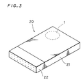
- the lithium battery 1 is employable within a memory card body 21 as shown in Fig. 3, for example. When thus incorporated in a memory card 20, the lithium battery 1 performs backing up function.
- the portion with a reference number 22 is a connector.
- the charge capacity Q of the lithium battery 1 which is employable in the memory card 20 is around 165mAH, and a consumption current I(20) of the SRAM is 17 ⁇ A at the room temperature t of 20 °C.
- the lithium battery 1 must be exchanged in about 1.1 year.
- the consumption current I(t) of the SRAM increases with increase in the temperature t . Assuming that the temperature t is 50°C, the consumption current I(50) becomes 85 ⁇ A.
- the exchange of the lithium battery 1 for a new one must be made in about 0.22 year.
- the lithium battery 1 is employed as a backup power source within the memory card 20, regular measurements of voltage drop in the lithium battery 1 are necessary to know when to exchange the lithium battery 1.
- the conventional lithium battery 1 does not comprise means for indicating its life time or to what degree its voltage has dropped. Instead, a voltage measurement apparatus is widely used to measure the voltage drop. However, such measurement is not satisfactory because the measurement of the voltage drop is rather complicated. To deal with this, a lithium battery in which an apparatus for indicating life time is integrated is demanded, which obviously has not been attained yet. Aside from lithium batteries, other batteries such as manganese batteries and nickel cadmium batteries have similar unfulfilled demands.
- US-A-1497388 shows a battery fitted with a lifetime indicator, which is attached externally to the battery casing.
- JP-A-59-016283 shows a button cell incorporating a condition indication electrode placed between an external terminal portion of the cell casing, and an internal electrode of the cell.
- WO 90/02432 discloses a battery of cells provided with additional circuitry and sensors to enable the battery to monitor its own condition.
- the separate monitor package has a solid state display.
- JP-A-63-205065 shows a cell fitted with a light emitting diode to indicate the charge state.
- JP-A-57-134869 describes a power supply incorporating a battery and provided with a fuse-type timer indicator.
- the present invention is directed to a battery comprising a power source for generating electric power, positive and negative containers connected to the said power source, an insulating member located between the said positive and negative containers for providing insulation therebetween, and an indicator implant for indicating the remaining life of the battery, the said implant comprising first and second electrodes respectively connected to the said positive and negative containers, characterised in that the indicator implant is removable.
- the life time indicator may comprise: an indication element having first and second electrodes, the indication element having a characteristic of which the indication by the indication element changes according to the voltage difference between the first and second electrodes; first connection means for connecting the first electrode to the positive container; and second connection means for connecting the second electrode to the negative container.
- the life time indicator has an external thread portion, while the battery unit has an internal thread portion, the external and internal thread portions being engageable with each other.
- Fig. 4 is a cross sectional view of a battery 1A.
- the major difference, which the lithium battery 1A shows against the conventional battery of Fig. 2, is that it comprises a life time indicator 30 provided in the bottom portion of a positive container 11.
- the life time indicator 30 for indicating the life time of the battery 1A includes a block member 31 which has a configuration that allows it to be integrated with the positive container 11 through insulating seal member 17 (Fig. 4).
- the block member 31 is precisely engageable with the positive container 11 lest any portion of the life time indicator 30 should protrude from the positive container 11.
- the configuration of the block member 31 is not limited to this. Neither is the material of the block member 31.
- the block member 31 has a recess 31a as shown in Figs. 5A and 5B.
- An indication element 32 is fixed to the bottom of recess 31a.
- the indication element 32 varies its indications depending on a voltage impressed onto the same. Thus, indications of the indication element 32 can be observed through an opening 31b of the recess 31a.
- the indication element 32 will be described in detail regarding structural and operational aspects.
- the recess 31a of the block member 31 has, at its bottom portion, through holes 33a and 33b bored therein.
- a covered lead wire 34a provided therein electrically connects an end portion 32a of the indication element 32 and the positive pole container 11.
- another covered lead wire 34b electrically connects another end portion 32b of the indication element 32 and the negative pole container 15 through the through hole 33b and a through hole 17b. Due to the electric connection, a voltage of the lithium battery 1A would be applied to the indication element 32. The electric potential of the impressed voltage determines what indications the indication element 32 displays. When voltage drop is caused in a discharging lithium battery 1A, the indication of the indication element 32 changes accordingly. This serves as a clear sign or warning that the lithium battery 1A is running out of its life time (i.e., voltage drop is occurring).
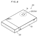
- the lithium battery 1A is incorporated in a memory card body 21 to function as a backup power source of a memory card 20 as shown in Fig. 6.
- the life time indicator 30 directs the opening 31b outside, owing to which the life time indicator 30 can be seen from outside through a window 23 provided in the memory card body 21.
- the life time of the lithium battery 1A can be known by observing indications of the indication element 32 without taking out the lithium battery 1A from the memory card 20.
- An electrochromic element is one candidate for the indication element 32.
- An electrochromic element is characterized in that the color of the material thereof changes according to an impressed voltage. This is called “electrochromism.”
- Well known electrochromic elements are, for example, those made of tungsten oxide.
- An indication element 32 made of tungsten oxide shows blue color when it receives an impressed voltage, whereas it restores its original color when an impressed voltage is small or zero. By utilizing this characteristic, the life time indication as above can be attained. While the voltage of the lithium battery 1A is large enough, the indication element 32 is blue. If voltage drop according to discharge occurs in the battery 1A, the indication element 32 loses its blue color, showing that the life time of the lithium battery 1A is running out.
- a viologen derivative can be used for the indication element 32.
- Receiving a proper voltage e.g., 0.5V or more
- a non-colored indication element 32 becomes colored as similar to the case where tungsten oxide is used.
- the indication element 32 with a voltage impressed thereon can show various colors such as red, violet, blue and green.
- ruthenium diphthalocyanine Other materials which exhibit many colors according to an impressed voltage can be used as electrochromic material.
- Ruthenium diphthalocyanine gradually changes its color according to an impressed voltage: purple with an impressed voltage in the range from -1.5V to -1.OV; blue in the range from -1.0 to -0.5V; green in the range from -0.5V to +0.5V; reddish brown in the range from +0.5V to +1.0V; and red in the range from +1.0V to +1.5V.
- ruthenium diphthalocyanine it is possible to obtain detailed information about not only the life time but also the voltage of the lithium battery 1A.
- Figs. 7A and 7B are diagrams illustrating an example of the indication element 32 formed by an electrophoretic cell.
- the indication element 32 consists of a transparent electrode 35 and an electrode 36 sandwiching a solvent layer 37 (e.g., fluorinated oil) in which charged particles 38 are scattered, the charged particles 38 being made of, for example, titanium dioxide coated with a macro-molecular material. Different colors are assigned to the charged particles 38 and the solvent layer 37.
- a voltage is impressed onto the electrodes 35 and 36, the charged particles 38 move toward and gather at the transparent electrode 35 (Fig. 7B).
- the color of the indication element 32 recognized through the transparent electrode 35 changes from the color of the solvent layer 37 to the color of the charged particles 38.
- the opposite would occur if the lithium battery 1A discharges and the voltage thereof drops.
- the indication element 32 gradually becomes light colored.
- nematic liquid crystal may be used, for instance. With no voltage impressed thereon, the indication element 32 (i.e., a liquid crystal cell) is bright, whereas it becomes dark when a voltage is impressed on it.
- the life time indicator 30 may be freely mounted to and dismounted from the positive pole container 11. Now, a lithium battery in which mounting and dismounting of a life time indicator are possible will be described.
- Fig. 8 is a cross sectional view of a battery according to an embodiment of the present invention.
- a life time indicator 40 is mountable to and dismountable from a positive pole container 11. Except for this point, the lithium battery 1B has approximately the same structures as those of the conventional lithium battery 1 of Fig. 2, and therefore, description of the same is omitted here.
- Fig. 9 is a cross sectional view
- Fig. 10 is a top plan view
- Fig. 11 is a bottom plan view of the life time indicator 40.
- the life time indicator 40 includes a cylindrical conductive block member 41.
- An external thread 41a is formed on the peripheral portion of the conductive block member 41.
- an internal thread 11a is formed on the side wall of a recess which is provided in the positive pole container 11. The threads 41a and 11a are engageable with each other.
- the columnar block member 41 can be mounted to and dismounted from the positive pole container 11.
- the block member 41 includes a recess 41b with an indication element 42 fixed on its bottom, the indication element 42 consisting of an electrochromic cell, an electrophoretic cell, or a liquid crystal cell described as above.
- the indication element 42 consisting of an electrochromic cell, an electrophoretic cell, or a liquid crystal cell described as above.
- indications of the indication element 42 can be seen from outside through an opening 41c of the recess 41b.
- the opening 41c is rectangular in configuration as shown in Fig. 11. By turning a coin or the like inserted into the rectangular opening 41c, the block member 41 is dismounted from the positive pole container 11.
- the block member 41 is provided with a hole at the center portion of the bottom of the recess 41b (Fig. 9).
- An insulating seal member 43 is inserted in the hole.
- a conductive block member 44 is inserted in the insulating seal member 43.
- the conductive block member 44 is fixed to the block member 41 while insulated from the block member 41.
- the conductive block member 44 is electrically connected to the indication element 42 by a lead wire 45a connecting the same and an end portion 42a of the indication element 42.
- the conductive block member 44 becomes electrically connected to an electrode 46 (Fig. 8).
- the electrode 46 is fixed to the positive container 11 such that it is insulated from both the positive container 11 and a positive pole 12.
- the electrode 46 is electrically connected to a negative pole container 15 by means of a covered lead wire 47.
- the end portion 42a of the indication element 42 becomes electrically connected to the negative pole container 15 through the lead wire 45a, the conductive block member 44, the electrode 46 and the lead wire 47.
- another end portion 42b of the indication element 42 is connected to the block member 41 by a lead wire 45b.
- mounting of the block member 41 to the positive pole container 11 makes the indication element 42 electrically connected to the block member 41. Owing to this, when the voltage of the lithium battery 1B is applied to the indication element 42, the indication element 42 shows indication corresponding to the applied voltage.
- the life time of the lithium battery 1B is known.
- the lithium battery 1B is still further advantageous. Since the life time indicator 40 can be freely mounted and dismounted, it is possible that the indication element 40 is not mounted except when voltage drop needs to be measured. Hence, the life time indicator 40 causes only minimum discharge of the battery 1B.
- the foregoing relates exclusively to lithium batteries, however, the present invention has a broader applicable field.
- the present invention can be applied to primary batteries such as manganese batteries and secondary batteries such as nickel cadmium batteries.
- the life time indicator can be mounted to the negative pole container.
- the life time indicator does not necessarily have to be mounted to the bottom portion of the container, but can be mounted to the top or the side portion of the container.
Landscapes
- Engineering & Computer Science (AREA)
- Manufacturing & Machinery (AREA)
- Chemical & Material Sciences (AREA)
- Chemical Kinetics & Catalysis (AREA)
- Electrochemistry (AREA)
- General Chemical & Material Sciences (AREA)
- Secondary Cells (AREA)
- Tests Of Electric Status Of Batteries (AREA)
Claims (13)
- Eine Batterie miteiner Energiequelle (12, 13, 14) zur Erzeugung elektrischer Leistung; positiven und negativen Behältern (15, 11), die mit der Energiequelle (12, 13, 14) verbunden sind; einem isolierenden Bauteil (16), das zwischen den positiven und negativen Behältern (15, 11) angeordnet ist, um eine Isolation zwischen diesen zu schaffen, undeinem Anzeigeeinsatz (30) zur Anzeige der Restlebensdauer der Batterie, wobei der Einsatz (30) erste und zweite Elektroden (32a, 32b) aufweist, welche entsprechend mit dem positiven und negativen Behälter (11, 15) verbunden sind, dadurch gekennzeichnet, daß der Anzeigeeinsatz (30) entfernbar ist.
- Eine Batterie nach Anspruch 1, wobei der Anzeigeeinsatz ein Anzeigeelement aufweist, das eine Charakteristik hat, die sich abhängig von einem Spannungsabstand zwischen den ersten und zweiten Elektroden ändert.
- Eine Batterie nach Anspruch 1 oder 2, wobei der Anzeigeeinsatz aufweist:erste Verbindungsmittel zum Verbinden der ersten Elektrode mit dem positiven Behälter; undzweite Verbindungsmittel zum Verbinden der zweiten Elektrode mit dem negativen Behälter.
- Eine Batterie nach Anspruch 2 oder 3, wobei das Anzeigeelement ein elektrochromes Element ist.
- Eine Batterie nach Anspruch 4, wobei das elektrochrome Element aus Wolframoxid gemacht ist.
- Eine Batterie nach Anspruch 4, wobei das elektrochrome Element aus Ruthenium-Diphtalocyanin gemacht ist.
- Eine Batterie nach Anspruch 2 oder 3, wobei das Anzeigeelemtent aus einem Viologen-Derivat gemacht ist.
- Eine Batterie nach Anspruch 2 oder 3, wobei das Anzeigeelement aus einer elektrophoretischen Zelle gemacht ist.
- Eine Batterie nach Anspruch 8, wobei die erste Elektrode transparent ist und die elektrophoretische Zelle eine Lösungsmittelschicht zwischen den ersten und zweiten Elektroden und eine Vielzahl von geladenen Partikeln aufweist, die in der Lösungsmittelschicht verteilt sind.
- Eine Batterie nach Anspruch 9, wobei jedes der geladenen Partikel aus einem Partikel aus Titanoxid besteht, das mit einem makromolekularen Material überzogen ist.
- Eine Batterie nach Anspruch 2 oder 3, wobei das Anzeigeelement aus einem Flüssigkristall gemacht ist.
- Eine Batterie nach einem der vorhergehenden Ansprüche, wobei der Anzeigeeinsatz einen Außengewindeabschnitt aufweist, wohingegen die Batterie eine Ausnehmung mit einem Innengewindeabschnitt aufweist wobei die Außen- und Innengewindeabschnitte miteinander in Eingriff bringbar sind, um den Einsatz sicher innerhalb der Vertiefung zu halten.
- Eine Batterie nach Anspruch 12, wobei der Anzeigeeinsatz eine rechteckförmige Öffnung aufweist.
Applications Claiming Priority (2)
| Application Number | Priority Date | Filing Date | Title |
|---|---|---|---|
| JP8560/91 | 1991-01-28 | ||
| JP3008560A JPH04262277A (ja) | 1991-01-28 | 1991-01-28 | 電池 |
Publications (2)
| Publication Number | Publication Date |
|---|---|
| EP0501609A1 EP0501609A1 (de) | 1992-09-02 |
| EP0501609B1 true EP0501609B1 (de) | 1996-05-29 |
Family
ID=11696479
Family Applications (1)
| Application Number | Title | Priority Date | Filing Date |
|---|---|---|---|
| EP92300704A Expired - Lifetime EP0501609B1 (de) | 1991-01-28 | 1992-01-28 | Batterie |
Country Status (4)
| Country | Link |
|---|---|
| US (1) | US5256500A (de) |
| EP (1) | EP0501609B1 (de) |
| JP (1) | JPH04262277A (de) |
| DE (1) | DE69211032T2 (de) |
Cited By (1)
| Publication number | Priority date | Publication date | Assignee | Title |
|---|---|---|---|---|
| TWI797650B (zh) * | 2020-11-12 | 2023-04-01 | 邑流微測股份有限公司 | 鈕扣電池測試裝置 |
Families Citing this family (35)
| Publication number | Priority date | Publication date | Assignee | Title |
|---|---|---|---|---|
| US5015544A (en) | 1989-02-08 | 1991-05-14 | Strategic Energy Ltd. | Battery with strength indicator |
| CA2056139C (en) * | 1991-01-31 | 2000-08-01 | Eveready Battery Company, Inc. | Electrochromic thin film state-of-charge detector for on-the-cell application |
| US5737114A (en) * | 1991-01-31 | 1998-04-07 | Eveready Battery Company, Inc. | Label having an incorporated electrochromic state-of-charge indicator for an electrochemical cell |
| US5672440A (en) * | 1991-01-31 | 1997-09-30 | Eveready Battery Company | Cell tester device employing a cathodically depositable metal ion electrolyte solution |
| JPH04359872A (ja) * | 1991-06-07 | 1992-12-14 | Nec Corp | バッテリーパック |
| US5156931A (en) | 1991-12-31 | 1992-10-20 | Strategic Energy Ltd. | Battery with strength indicator |
| US5830596A (en) * | 1993-05-03 | 1998-11-03 | Morgan Adhesives, Inc. | Method for producing battery tester label and resulting label and battery assembly |
| US5389458A (en) * | 1993-05-03 | 1995-02-14 | Eveready Battery Company, Inc. | Battery with tester label and method for producing it |
| US5393618A (en) * | 1993-05-03 | 1995-02-28 | Eveready Battery Company, Inc. | Battery with tester label and method for producing it |
| CA2134606A1 (en) | 1993-11-01 | 1995-05-02 | Eveready Battery Company, Inc. | Portable lighting device having externally attached voltage tester |
| US5372898A (en) * | 1994-02-17 | 1994-12-13 | The United States Of America As Represented By The Secretary Of The Army | Universal inexpensive battery state-of-charge indicator |
| DE4420087C2 (de) * | 1994-06-09 | 1998-11-19 | Dieter Lueken | Einrichtung zur Kenntlichmachung eines vorbestimmten Ladungszustandes von Primär- oder Sekundärelementen |
| US6118426A (en) * | 1995-07-20 | 2000-09-12 | E Ink Corporation | Transducers and indicators having printed displays |
| JPH10304578A (ja) * | 1997-04-21 | 1998-11-13 | Canon Inc | 電気機器及び電気機器の運用制御方法 |
| US6156450A (en) * | 1997-07-24 | 2000-12-05 | Eveready Battery Company, Inc. | Battery tester having printed electronic components |
| US6154263A (en) | 1997-07-25 | 2000-11-28 | Eveready Battery Company, Inc. | Liquid crystal display and battery label including a liquid crystal display |
| US6833217B2 (en) | 1997-12-31 | 2004-12-21 | Duracell Inc. | Battery cathode |
| JP4651193B2 (ja) | 1998-05-12 | 2011-03-16 | イー インク コーポレイション | ドローイングデバイス用途のためのマイクロカプセル化した電気泳動性の静電的にアドレスした媒体 |
| AU6295899A (en) | 1998-10-07 | 2000-04-26 | E-Ink Corporation | Illumination system for nonemissive electronic displays |
| US6051957A (en) * | 1998-10-21 | 2000-04-18 | Duracell Inc. | Battery pack having a state of charge indicator |
| US6232782B1 (en) * | 1999-04-16 | 2001-05-15 | The Gillette Company | On cell circumferential battery indicator |
| US6294284B1 (en) * | 1999-04-16 | 2001-09-25 | The Gillette Company | Gauge effect battery tester |
| US6291096B1 (en) * | 1999-04-16 | 2001-09-18 | The Gillette Company | Pass/fail battery indicator and tester |
| US8009348B2 (en) | 1999-05-03 | 2011-08-30 | E Ink Corporation | Machine-readable displays |
| US7119759B2 (en) | 1999-05-03 | 2006-10-10 | E Ink Corporation | Machine-readable displays |
| EP1312926A1 (de) * | 2001-11-20 | 2003-05-21 | Abb Research Ltd. | Binärer Spannungsanzeiger |
| US20070024460A1 (en) * | 2005-08-01 | 2007-02-01 | Clark Richard L | Electrical apparatus with voltage drop indicator |
| US8902568B2 (en) | 2006-09-27 | 2014-12-02 | Covidien Lp | Power supply interface system for a breathing assistance system |
| US8302600B2 (en) | 2008-09-30 | 2012-11-06 | Nellcor Puritan Bennett Llc | Battery management for a breathing assistance system |
| US8776790B2 (en) | 2009-07-16 | 2014-07-15 | Covidien Lp | Wireless, gas flow-powered sensor system for a breathing assistance system |
| US8547062B2 (en) | 2009-12-02 | 2013-10-01 | Covidien Lp | Apparatus and system for a battery pack assembly used during mechanical ventilation |
| CN102590759A (zh) * | 2012-02-23 | 2012-07-18 | 帝发技术(无锡)有限公司 | 汽车电量状态显示器 |
| USD775345S1 (en) | 2015-04-10 | 2016-12-27 | Covidien Lp | Ventilator console |
| DE102018212837A1 (de) * | 2018-08-01 | 2020-02-06 | Audi Ag | Vorrichtung und Verfahren zur optischen Spannungsdetektion bei Brennstoffzellen |
| CN112713346B (zh) * | 2020-12-15 | 2022-09-20 | 宁波卓越印务有限公司 | 可提示电池新旧的电池标签 |
Family Cites Families (12)
| Publication number | Priority date | Publication date | Assignee | Title |
|---|---|---|---|---|
| US1497388A (en) * | 1922-11-03 | 1924-06-10 | Edward M Sterling | Method of and apparatus for indicating the electrical condition of a cell |
| US3773563A (en) * | 1972-02-22 | 1973-11-20 | Carbone Corp | Life indicator for primary carbon zinc batteries |
| US4379816A (en) * | 1980-09-22 | 1983-04-12 | General Electric Company | Indicator of full charge for secondary cell or battery thereof |
| US4329406A (en) * | 1981-03-27 | 1982-05-11 | Dahl Ernest A | Specific gravity transducer and battery performance indicator |
| DE3148860A1 (de) * | 1981-12-10 | 1983-06-23 | Wolfgang 1000 Berlin Köpke | Elektrochemisches element mit eingebauter elektronischer zusatzschaltung |
| US4497881A (en) * | 1983-01-31 | 1985-02-05 | Bertolino Renee Z | Battery charge indicator |
| JPS60112248A (ja) * | 1983-11-22 | 1985-06-18 | Matsushita Electric Ind Co Ltd | 鉛蓄電池 |
| US4835475A (en) * | 1986-11-17 | 1989-05-30 | Niichi Hanakura | Battery tester including a thermochromic material |
| JPS63205065A (ja) * | 1987-02-20 | 1988-08-24 | Nec Corp | 蓄電池 |
| DE3878383T2 (de) * | 1987-10-06 | 1993-09-09 | Sharp Kk | Sekundaerbatterie. |
| US5159272A (en) * | 1988-07-27 | 1992-10-27 | Gnb Incorporated | Monitoring device for electric storage battery and configuration therefor |
| AU4202489A (en) * | 1988-08-31 | 1990-03-23 | Christopher John Fairgrieve | Battery with charge control system |
-
1991
- 1991-01-28 JP JP3008560A patent/JPH04262277A/ja active Pending
-
1992
- 1992-01-21 US US07/822,949 patent/US5256500A/en not_active Expired - Fee Related
- 1992-01-28 EP EP92300704A patent/EP0501609B1/de not_active Expired - Lifetime
- 1992-01-28 DE DE69211032T patent/DE69211032T2/de not_active Expired - Fee Related
Cited By (1)
| Publication number | Priority date | Publication date | Assignee | Title |
|---|---|---|---|---|
| TWI797650B (zh) * | 2020-11-12 | 2023-04-01 | 邑流微測股份有限公司 | 鈕扣電池測試裝置 |
Also Published As
| Publication number | Publication date |
|---|---|
| DE69211032D1 (de) | 1996-07-04 |
| DE69211032T2 (de) | 1996-10-02 |
| US5256500A (en) | 1993-10-26 |
| JPH04262277A (ja) | 1992-09-17 |
| EP0501609A1 (de) | 1992-09-02 |
Similar Documents
| Publication | Publication Date | Title |
|---|---|---|
| EP0501609B1 (de) | Batterie | |
| US6045941A (en) | Method to determine the state of charge and remaining life of lithium batteries used in oilfield services applications | |
| JP3265433B2 (ja) | 電池取付用エレクトロクロミック薄膜充電検知器 | |
| EP0848826B1 (de) | Batteriezustandstester | |
| USRE39703E1 (en) | Battery with strength indicator | |
| EP0805978B1 (de) | Batteriezustandsprüfgerät | |
| EP1061593B1 (de) | Batteriesatz | |
| US4497881A (en) | Battery charge indicator | |
| CA1149015A (en) | State of charge battery monitor | |
| WO1992022100A1 (en) | A battery charge indicator | |
| US5936382A (en) | Battery electrolyte level monitor | |
| US4948683A (en) | Reserve activated electrochemical cell with a cell condition checking apparatus | |
| EP1543335B1 (de) | Passiver anzeiger der spannungspräsenz | |
| JP3033209B2 (ja) | シール形鉛蓄電池およびその残存容量検知方法 | |
| KR200380689Y1 (ko) | 온도측정 및 표시장치를 구비하는 축전지 | |
| JPS58117470A (ja) | 蓄電池監視装置 | |
| JPH0132026Y2 (de) | ||
| ZAROMB et al. | Electrochemical methane sensor[Patent Application] | |
| HK1031474B (en) | Battery pack |
Legal Events
| Date | Code | Title | Description |
|---|---|---|---|
| PUAI | Public reference made under article 153(3) epc to a published international application that has entered the european phase |
Free format text: ORIGINAL CODE: 0009012 |
|
| AK | Designated contracting states |
Kind code of ref document: A1 Designated state(s): DE FR GB |
|
| 17P | Request for examination filed |
Effective date: 19930210 |
|
| 17Q | First examination report despatched |
Effective date: 19940617 |
|
| GRAH | Despatch of communication of intention to grant a patent |
Free format text: ORIGINAL CODE: EPIDOS IGRA |
|
| GRAA | (expected) grant |
Free format text: ORIGINAL CODE: 0009210 |
|
| AK | Designated contracting states |
Kind code of ref document: B1 Designated state(s): DE FR GB |
|
| REF | Corresponds to: |
Ref document number: 69211032 Country of ref document: DE Date of ref document: 19960704 |
|
| REG | Reference to a national code |
Ref country code: GB Ref legal event code: 727 |
|
| REG | Reference to a national code |
Ref country code: GB Ref legal event code: 727A |
|
| ET | Fr: translation filed | ||
| REG | Reference to a national code |
Ref country code: GB Ref legal event code: 727B |
|
| REG | Reference to a national code |
Ref country code: GB Ref legal event code: SP |
|
| PLBE | No opposition filed within time limit |
Free format text: ORIGINAL CODE: 0009261 |
|
| 26N | No opposition filed | ||
| PGFP | Annual fee paid to national office [announced via postgrant information from national office to epo] |
Ref country code: DE Payment date: 20010122 Year of fee payment: 10 |
|
| PGFP | Annual fee paid to national office [announced via postgrant information from national office to epo] |
Ref country code: GB Payment date: 20010124 Year of fee payment: 10 |
|
| PGFP | Annual fee paid to national office [announced via postgrant information from national office to epo] |
Ref country code: FR Payment date: 20010125 Year of fee payment: 10 |
|
| REG | Reference to a national code |
Ref country code: GB Ref legal event code: IF02 |
|
| PG25 | Lapsed in a contracting state [announced via postgrant information from national office to epo] |
Ref country code: GB Free format text: LAPSE BECAUSE OF NON-PAYMENT OF DUE FEES Effective date: 20020128 |
|
| PG25 | Lapsed in a contracting state [announced via postgrant information from national office to epo] |
Ref country code: DE Free format text: LAPSE BECAUSE OF NON-PAYMENT OF DUE FEES Effective date: 20020801 |
|
| GBPC | Gb: european patent ceased through non-payment of renewal fee |
Effective date: 20020128 |
|
| PG25 | Lapsed in a contracting state [announced via postgrant information from national office to epo] |
Ref country code: FR Free format text: LAPSE BECAUSE OF NON-PAYMENT OF DUE FEES Effective date: 20020930 |
|
| REG | Reference to a national code |
Ref country code: FR Ref legal event code: ST |