EP0501133B1 - Retractable head lamp for vehicle particularly for a passenger car - Google Patents
Retractable head lamp for vehicle particularly for a passenger car Download PDFInfo
- Publication number
- EP0501133B1 EP0501133B1 EP92100865A EP92100865A EP0501133B1 EP 0501133 B1 EP0501133 B1 EP 0501133B1 EP 92100865 A EP92100865 A EP 92100865A EP 92100865 A EP92100865 A EP 92100865A EP 0501133 B1 EP0501133 B1 EP 0501133B1
- Authority
- EP
- European Patent Office
- Prior art keywords
- support member
- headlamp according
- pivotable
- pivotable headlamp
- lever
- Prior art date
- Legal status (The legal status is an assumption and is not a legal conclusion. Google has not performed a legal analysis and makes no representation as to the accuracy of the status listed.)
- Expired - Lifetime
Links
Images

Classifications
-
- B—PERFORMING OPERATIONS; TRANSPORTING
- B60—VEHICLES IN GENERAL
- B60Q—ARRANGEMENT OF SIGNALLING OR LIGHTING DEVICES, THE MOUNTING OR SUPPORTING THEREOF OR CIRCUITS THEREFOR, FOR VEHICLES IN GENERAL
- B60Q1/00—Arrangement of optical signalling or lighting devices, the mounting or supporting thereof or circuits therefor
- B60Q1/02—Arrangement of optical signalling or lighting devices, the mounting or supporting thereof or circuits therefor the devices being primarily intended to illuminate the way ahead or to illuminate other areas of way or environments
- B60Q1/04—Arrangement of optical signalling or lighting devices, the mounting or supporting thereof or circuits therefor the devices being primarily intended to illuminate the way ahead or to illuminate other areas of way or environments the devices being headlights
- B60Q1/05—Arrangement of optical signalling or lighting devices, the mounting or supporting thereof or circuits therefor the devices being primarily intended to illuminate the way ahead or to illuminate other areas of way or environments the devices being headlights retractable
Definitions
- the invention relates to a pivotable headlamp according to the preamble of claim 1.
- a generic headlight is known (DE-B-2708 374), which delivers good results with regard to headlight function and safety precaution - personal protection and motor overload protection. At the same time, it offers room for constructive improvements, especially in order to be able to easily replace its lamp body.
- the main advantages achieved with the invention are the fact that the headlight can be moved into an assembly position and can be fixed in this position with a fixing device, as a result of which not only the lamp body of the headlight can be easily replaced, but also electrical cables or other components of the headlight can be easily checked - can also be repaired if necessary.
- the mounting position can be implemented in a structurally advantageous manner if the carrying device comprises two links which can be rotated relative to one another and which are held in position by means of a latching device. This construction also ensures that people standing on the vehicle are not injured by the pivoting movement of the headlamp and that the electric motor of the actuating device is not damaged when resistance is applied to the headlamp.
- the fixing device with which the headlight is unlocked from the working position and can be fixed in the mounting position, is, on the one hand, a component that can be realized with clear means. It is also easy to operate from the engine compartment.
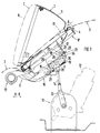
- a pivotable headlight 1 is arranged in the bow 2 of a passenger car, not shown.
- a fender 3 has an opening 4 for receiving the headlight 1.
- the headlight 1 comprises a housing 5, a lens 6, a reflector 7 (FIG. 2) and at least one lamp body 8.
- the housing 5 is dome-shaped and extends between the lens 6 and a collar-like cover 8 'arranged at a distance from the latter. whose circumference is slightly smaller than that of the opening 4 - distance A -.
- an actuator is designated, which is formed by an electric motor 12 and a crank mechanism 13.
- the Crank gear 13 engages with a push rod 14 in the carrying device 9.
- the headlight 1 can be pivoted from a working position I into a retracted rest position II and vice versa by the shaft 10 and the actuating device 11.
- the direction of rotation is clockwise, provided that the passenger car assumes a position "moving from right to left".
- the lens 6 In the rest position II, the lens 6 is visible and inclined in the structure of the fender 3; In working position II, where the crank mechanism 13 is almost dead center, the lens 6 is more upright.
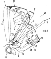
- the headlamp 1 can be moved manually into an assembly position III (FIG. 2) and fixed there by means of a fixing device 15.
- the carrying device 9 has two links 16, 17.
- the first link 16 is connected to the actuating device 11 and is fixedly attached to the shaft 10.
- the second link 17 is mounted on the shaft 10 so as to be movable relative to the first link 16; the second link 17 carries the headlamp 1.
- a latching device 18 is effective between the first link 16 and the second link 17 and is fastened to the carrier device 9 at a distance from the shaft 10.
- the latching device 18 comprises a spring-loaded, pivotable lever 19, which is provided on a free side 20 with a support element 22 having a slide roller 21.
- the support element 22 engages behind a link 23.
- the lever 19 is attached to the first link 16.
- the backdrop 23 is provided on a support wall 24.
- the backdrop 23 forms an incline to the support wall 24 and merges into a run-up track 26 after a tip 25.
- a fixed stop 27 is arranged on the first link 16 and, in the working position I, bears against a first support side 28 of a support member 29 of the fixing device 15. In the assembly position III, however, the stop 27 rests on a second support side 30 of the support member 29.
- the support member 29 is a cylindrical component with a square cross section and axially movable, approximately parallel to the shaft 10. By Axial movements of the support member 29 - in the direction CC - (FIG. 4), the stop 27 can be brought into contact with the first support side 28 or the second support side 30.
- the axial movements C-C of the support member 29 are accomplished by partial circular movements in the area ⁇ of a lever 31 which is provided with a handle 32.
- a transmission device 33 is provided between the lever 31 and the support member 29.
- the transmission device 33 comprises a pivot pin 34 and a driver 35 mounted transversely thereto, which cooperates with a thread-like groove 36 in the support member 29 to transmit it away; the groove 36 has a relatively elongated slope (short rotational movement; long stroke).
- the lever 31, the transmission device 33 and the support member 29 are assigned to a housing 37 of the fixing device 15, which has a bearing section 38 for the pivot 34 and a guide section 39 for the support member 29.
- the pivot pin 34 is surrounded by a compression spring 40 which tries to move the support member 29 into its extended position D.
- a mounting flange 41 extends between the bearing section 38 and the guide section 39, e.g. is held on a fixed wall delimiting an engine compartment by means of screws. With this arrangement, the handle 32 is accessible after opening a hood.
- the support member 28 has an inner tube section 42 and an outer tube section 43.
- the inner pipe section 42 comprises the groove 36 and a circular cross section.
- the tube section 42 is covered with a cover 44.
- the headlight 1 is first brought into the operating position I. Thereafter, the handle 32 is moved from the position E to the position F by disengaging the locking device 18, whereby the support member 29 is retracted (position H). The stop 27 is now released and the headlight 1 can be moved manually into the mounting position III by disengaging the locking device 18. After the handle 32 assumes its position D, supported by the compression spring 34, the headlight 1 is in the operating position III fixed. Between the cover 8 'and the fender 3, a gap 45 is provided in the latter position (FIG. 2), through which the lamp body 8 - possibly also other components - is accessible.
Description
Die Erfindung betrifft einen schwenkbaren Scheinwerfer nach dem Oberbegriff des Patentanspruchs 1.The invention relates to a pivotable headlamp according to the preamble of
Es ist ein gattungsgemäßer Scheinwerfer bekannt (DE-B-2708 374), der bezüglich Scheinwerferfunktion und Sicherheitsvorkehrung - Personenschutz und Motorüberlastsicherung - gute Ergebnisse liefert. Gleichwohl bietet er Raum für konstruktive Verbesserungen, namentlich um seinen Leuchtenkörper leicht auswechseln zu können.A generic headlight is known (DE-B-2708 374), which delivers good results with regard to headlight function and safety precaution - personal protection and motor overload protection. At the same time, it offers room for constructive improvements, especially in order to be able to easily replace its lamp body.
Es ist deshalb Aufgabe der Erfindung, an dem schwenkbaren Scheinwerfer solche Vorkehrungen zu treffen, daß der Leuchtenkörper zum Wechseln gegebenenfalls auch elektrische Kabel, Teile der Betätigungsvorrichtung oder dergleichen leicht zugänglich sind.It is therefore an object of the invention to take such precautions on the pivotable headlight that the lamp body for changing, if necessary, also electrical cables, parts of the actuating device or the like are easily accessible.
Erfindungsgemäß wird diese Aufgabe durch die kennzeichnenden Merkmale des Patentanspruchs 1 gelöst. Weitere, die Erfindung ausgestaltende Merkmale sind in den Unteransprüchen enthalten.According to the invention, this object is achieved by the characterizing features of
Die mit der Erfindung hauptsächlich erzielten Vorteile sind darin zu sehen, daß der Scheinwerfer in eine Montagestellung bewegbar und in dieser mit einer Fixierungsvorrichtung festsetzbar ist, wodurch nicht nur Leuchtenkörper des Scheinwerfers leicht austauschbar sind, sondern auch elektrische Kabel oder andere Bauteile des Scheinwerfers einfach überprüfbar - gegebenenfalls auch instandsetzbar sind. Die Montagestellung lässt sich konstruktiv günstig realisieren, wenn die Tragvorrichtung zwei relativ zueinander verdrehbare Glieder umfasst, die mittels einer Rastvorrichtung in Lage gehalten werden. Diese Konstruktion gewährleistet darüber hinaus, daß am Fahrzeug stehende Personen durch die Schwenkbewegung des Scheinwerfers nicht verletzt und bei Angriff eines Widerstandes am Scheinwerfer der Elektromotor der Betätigungsvorrichtung nicht beschädigt wird.The main advantages achieved with the invention are the fact that the headlight can be moved into an assembly position and can be fixed in this position with a fixing device, as a result of which not only the lamp body of the headlight can be easily replaced, but also electrical cables or other components of the headlight can be easily checked - can also be repaired if necessary. The mounting position can be implemented in a structurally advantageous manner if the carrying device comprises two links which can be rotated relative to one another and which are held in position by means of a latching device. This construction also ensures that people standing on the vehicle are not injured by the pivoting movement of the headlamp and that the electric motor of the actuating device is not damaged when resistance is applied to the headlamp.
Die Fixierungsvorrichtung, mit der der Scheinwerfer aus der Arbeitsstellung entriegelt und in der Montagestellung festsetzbar ist, ist zum einen ein mit übersichtlichen Mitteln zu verwirklichendes Bauteil. Außerdem ist sie vom Motorraum aus problemlos bedienbar.The fixing device, with which the headlight is unlocked from the working position and can be fixed in the mounting position, is, on the one hand, a component that can be realized with clear means. It is also easy to operate from the engine compartment.
In der Zeichnung wird ein Ausführungsbeispiel der Erfindung gezeigt, das nachstehend näher beschrieben ist.
Es zeigt
- Fig. 1
- eine Teilseitenansicht eines Personenwagens mit dem erfindungsgemäßen schwenkbaren Scheinwerfer,
- Fig. 2
- eine Teilansicht der Fig. 1 mit einer anderen Stellung des schwenkbaren Scheinwerfers,
- Fig. 3
- eine Einzelheit X der Fig. 1 in detaillierter Form und größerem Maßstab;
- Fig. 4
- einen Schnitt nach der Linie IV-IV der Fig. 3,
- Fig. 5
- eine Einzelheit Y der Fig. 4 in größerem Maßstab.
It shows
- Fig. 1
- 2 shows a partial side view of a passenger car with the pivotable headlight according to the invention,
- Fig. 2
- 1 with a different position of the pivotable headlight,
- Fig. 3
- a detail X of Figure 1 in a detailed form and on a larger scale.
- Fig. 4
- a section along the line IV-IV of Fig. 3,
- Fig. 5
- a detail Y of Fig. 4 on a larger scale.
Ein schwenkbarer Scheinwerfer 1 ist im Bug 2 eines nicht näher dargestellten Personenwagens angeordnet. Ein Kotflügel 3 weist eine Öffnung 4 zur Aufnahme des Scheinwerfers 1 auf.A
Der Scheinwerfer 1 umfasst ein Gehäuse 5, eine Streuscheibe 6, einen Reflektor 7 (Fig. 2) und wenigstens einen Leuchtenkörper 8. Das Gehäuse 5 ist kuppelartig ausgebildet und erstreckt sich zwischen der Streuscheibe 6 und einer entfernt von letzterer angeordneten kragenartigen Abdeckung 8', deren Umfang geringfügig kleiner ist als der der Öffnung 4 - Abstand A -.The
Zur Halterung des Scheinwerfers 1 dient eine Tragvorrichtung 9, die an einer Welle 10 gelagert ist; sie erstreckt sich quer zur Fahrzeuglängsrichtung B-B. Mit 11 ist eine Betätigungsvorrichtung bezeichnet, die durch einen Elektromotor 12 sowie ein Kurbelgetriebe 13 gebildet wird. Das Kurbelgetriebe 13 greift mit einer Schubstange 14 in der Tragvorrichtung 9 an.A
Durch die Welle 10 und die Betätigungsvorrichtung 11 ist der Scheinwerfer 1 aus einer Arbeitsstellung I in eine versenkte Ruhestellung II verschwenkbar und vice versa. Dabei ist die Drehrichtung unter der Voraussetzung, daß der Personenwagen eine Stellung "in Fahrtbewegung von rechts nach links" einnimmt, im Uhrzeigersinn. In der Ruhestellung II ist die Streuscheibe 6 sichtbar und geneigt in der Aufbauwand des Kotflügels 3 angebracht; in der Arbeitsstellung II, wo das Kurbelgetriebe 13 nahezu Totpunktlage einnimmt, ist die Streuscheibe 6 aufrechter. Aus der Arbeitsstellung II kann der Scheinwerfer 1 manuell in eine Montagestellung III bewegt (Fig. 2) und dort mittels einer Fixierungsvorrichtung 15 festgesetzt werden.The
Hierzu weist die Tragvorrichtung 9 zwei Glieder 16, 17 auf. Das erste Glied 16 ist mit der Betätigungsvorrichtung 11 verbunden und fest an der Welle 10 angebracht. Dagegen ist das zweite Glied 17 relativ beweglich zum ersten Glied 16 auf der Welle 10 gelagert; das zweite Glied 17 trägt den Scheinwerfer 1. Außerdem ist zwischen dem ersten Glied 16 und dem zweiten Glied 17 eine Rastvorrichtung 18 wirksam, die entfernt von der Welle 10 an der Tragvorrichtung 9 befestigt ist.For this purpose, the
Die Rastvorrichtung 18 umfasst einen federbelasteten, schwenkbaren Hebel 19, der an einer freien Seite 20 mit einem eine Gleitrolle 21 aufweisenden Stützelement 22 versehen ist. Das Stützelement 22 hintergreift eine Kulisse 23. Im Ausführungsbeispiel ist der Hebel 19 am ersten Glied 16 angebracht. Dagegen ist die Kulisse 23 an einer Tragwand 24 vorgesehen. Die Kulisse 23 bildet eine schräge zur Tragwand 24 und geht nach einer Spitze 25 in eine Anlaufbahn 26 über.The
Am ersten Glied 16 ist ein fester Anschlag 27 angeordnet, der in der Arbeitsstellung I an einer ersten Stützseite 28 eines Stützgliedes 29 der Fixierungsvorrichtung 15 anliegt. In der Montagestellung III dagegen ruht der Anschlag 27 an einer zweiten Stützseite 30 des Stützgliedes 29.A fixed
Das Stützglied 29 ist ein zylindrisches Bauteil mit viereckigem Querschnitt und axialbeweglich, und zwar etwa parallel, zur Welle 10 ausgebildet. Durch Axialbewegungen des Stützgliedes 29 - in Richtung C-C - (Fig. 4) kann der Anschlag 27 jeweils an der ersten Stützseite 28 oder der zweiten Stützseite 30 zur Anlage gebracht werden.The
Die Axialbewegungen C-C des Stützgliedes 29 werden durch Teilkreisbewegungen im Bereich α eines Hebels 31 bewerkstelligt, der mit einer Handhabe 32 versehen ist. Hierzu ist zwischen dem Hebel 31 und dem Stützglied 29 eine Übertragungseinrichtung 33 vorgesehen. Die Übertragungseinrichtung 33 umfasst einen Drehzapfen 34 und einen dazu quer angebrachten Mitnehmer 35, der mit einer gewindeartigen Nut 36 im Stützglied 29 wegübertragend zusammenwirkt; die Nut 36 weist eine relativ gestreckte Steigung auf (kurze Drehbewegung; langer Hub). Der Hebel 31, die Übertragungseinrichtung 33 und das Stützglied 29 sind einem Gehäuse 37 der Fixierungseinrichtung 15 zugeordnet, das einen Lagerabschnitt 38 für den Drehzapfen 34 und einen Führungsabschnitt 39 für das Stützglied 29 aufweist. Den Drehzapfen 34 umgibt eine Druckfeder 40, die das Stützglied 29 in seine ausgefahrene Stellung D zu bewegen sucht.The axial movements C-C of the
Zwischen Lagerabschnitt 38 und Führungsabschnitt 39 erstreckt sich ein Befestigungsflansch 41, der z.B. an einer festen, einen Motorraum begrenzenden Wand mittels Schrauben gehalten ist. Durch diese Anordnung ist die Handhabe 32 nach Öffnen einer Motorhaube zugänglich.A
Schließlich weist das Stützglied 28 einen inneren Rohrabschnitt 42 und einen äußeren Rohrabschnitt 43 auf. Der äußere Rohrabschnitt 43 - er ist ja viereckig - ruht in dem Führungsabschnitt 39. Der innere Rohrabschnitt 42 umfasst die Nut 36 und einen kreisförmigen Querschnitt. Auf der freien Seite des Stützgliedes 29 ist der Rohrabschnitt 42 mit einem Deckel 44 abgedeckt.Finally, the
Soll der Leuchtenkörper 7 gewechselt werden, wird der Scheinwerfer 1 zunächst in die Betriebsstellung I gebracht. Danach wird die Handhabe 32 durch Ausrücken der Rastvorrichtung 18 aus der Stellung E in die Stellung F gebracht, wodurch das Stützglied 29 eingezogen wird (Stellung H). Der Anschlag 27 ist jetzt freigegeben und der Scheinwerfer 1 kann manuell durch Ausrücken der Rastvorrichtung 18 in die Montagestellung III bewegt werden. Nachdem die Handhabe 32 ihre Stellung D, unterstützt durch die Druckfeder 34, wieder einnimmt, ist der Scheinwerfer 1 in der Betriebsstellung III festgelegt. Zwischen der Abdeckung 8' und dem Kotflügel 3 ist in letzterer Stellung ein Spalt 45 vorgesehen (Fig. 2), über den der Leuchtenkörper 8 - gegebenenfalls auch andere Bauteile - zugänglich ist.If the
Claims (13)
- A pivotable headlamp (1) for vehicles, in particular passenger cars, mounted rotatably on a shaft (10) by means of a support device (9) and movable from an operating position (I) into a lowered rest position (II) by way of an actuating device (11), wherein the headlamp (1) is articulated to the shaft (10) in such a way that the diffusing lens (6) thereof is mounted in a wall (3) of the body so as to be visible and inclined in the rest position (II), whereas the diffusing lens is more upright in the operating position, characterized in that the headlamp (1) is movable from the operating position (I) into an inclined assembly position (III), for example for changing a lighting element (8) and can be fixed there by means of a fixing device (15).
- A pivotable headlamp according to Claim 1, characterized in that the support device (9) comprises two members (16, 17), of which the first member (16) connected to the actuating device (11) is fixedly mounted on the shalt (10) and the second member (17) receiving the headlamp (1) is rotatably mounted on the shaft (10) relative to the first member (16), wherein a catch device (18) is provided between the first member (16) and the second member (17).
- A pivotable headlamp according to Claim 2, characterized in that the catch device (18) comprises a spring-loaded lever (19) which with a support member (22) engages behind a sliding block (23).
- A pivotable headlamp according to Claim 3, characterized in that the lever (19) is provided on the first member (16) and the sliding block (23) is provided on the second member (17).
- A pivotable headlamp according to one or more of the preceding Claims, characterized in that a fixed stop (27) is provided on the first member (16) and is supported on a first supporting side (28) of a support member (29) of the fixing device (15) in the operating position (I) and on a second supporting side (30) in the assembly position (III).
- A pivotable headlamp according to one or more of the preceding Claims, characterized in that the support member (29) is a cylindrical component, wherein the stop (27) can be made to abut on the supporting sides (28 or 30) of the support member (29) of the fixing device (15) by axial movements (C-C) thereof parallel to the shaft (10).
- A pivotable headlamp according to Claim 6, characterized in that the axial movements (C-C) of the support member (29) are formed by partial circular movements (area α) of a lever (31) provided with a handle (32) for example and connected to the support member (29) by way of a transmission device (33).
- A pivotable headlamp according to Claim 7, characterized in that the transmission device (33) has a pivot pin (34) with an entrainment means (35) arranged obliquely thereto and cooperating with a thread-like groove (36) of the support member (29).
- A pivotable headlamp according to one or more of the preceding Claims, characterized in that a housing (37) - consisting of plastics material for example - of the fixing device (15) has a bearing portion (38) for the pivot pin (34) and a guiding portion (39) for the support member (29).
- A pivotable headlamp according to one or more of the preceding Claims, characterized in that the pivot pin (34) is surrounded by a compression spring (40) urging the support member (29) into an extended position (D).
- A pivotable headlamp according to Claim 9, characterized in that a fastening flange (41) for the housing (37) is provided between the bearing portion (38) and the guiding portion (39).
- A pivotable headlamp according to one or more of the preceding Claims, characterized in that the support member (29) has an inner circular tube portion (42), provided with the groove (36), and an outer rectangular tube portion (43) resting in the corresponding guiding portion (39).
- A pivotable headlamp according to one or more of the preceding Claims, characterized in that the lever (32) with the handle (31) is accessible after opening a cover, for example the engine bonnet.
Applications Claiming Priority (2)
| Application Number | Priority Date | Filing Date | Title |
|---|---|---|---|
| DE4106091A DE4106091C1 (en) | 1991-02-27 | 1991-02-27 | |
| DE4106091 | 1991-02-27 |
Publications (2)
| Publication Number | Publication Date |
|---|---|
| EP0501133A1 EP0501133A1 (en) | 1992-09-02 |
| EP0501133B1 true EP0501133B1 (en) | 1994-08-31 |
Family
ID=6425967
Family Applications (1)
| Application Number | Title | Priority Date | Filing Date |
|---|---|---|---|
| EP92100865A Expired - Lifetime EP0501133B1 (en) | 1991-02-27 | 1992-01-20 | Retractable head lamp for vehicle particularly for a passenger car |
Country Status (2)
| Country | Link |
|---|---|
| EP (1) | EP0501133B1 (en) |
| DE (2) | DE4106091C1 (en) |
Families Citing this family (2)
| Publication number | Priority date | Publication date | Assignee | Title |
|---|---|---|---|---|
| DE19933768B4 (en) * | 1999-07-19 | 2007-12-13 | Volkswagen Ag | Luminaire of a vehicle |
| DE19951653A1 (en) | 1999-10-27 | 2001-05-03 | Volkswagen Ag | Multi-chamber lamp unit for a vehicle |
Family Cites Families (3)
| Publication number | Priority date | Publication date | Assignee | Title |
|---|---|---|---|---|
| DE2535677C2 (en) * | 1975-08-09 | 1984-08-30 | Dr.Ing.H.C. F. Porsche Ag, 7000 Stuttgart | Pivoting headlights for vehicles, in particular motor vehicles |
| GB1575517A (en) * | 1976-07-14 | 1980-09-24 | Lucas Industries Ltd | Manual headlamp tilting device in a motor vehicle |
| DE2708374C3 (en) * | 1977-02-26 | 1980-02-14 | Dr.Ing.H.C. F. Porsche Ag, 7000 Stuttgart | Pivoting headlights for vehicles, in particular passenger cars |
-
1991
- 1991-02-27 DE DE4106091A patent/DE4106091C1/de not_active Expired - Lifetime
-
1992
- 1992-01-20 EP EP92100865A patent/EP0501133B1/en not_active Expired - Lifetime
- 1992-01-20 DE DE59200420T patent/DE59200420D1/en not_active Expired - Fee Related
Also Published As
| Publication number | Publication date |
|---|---|
| EP0501133A1 (en) | 1992-09-02 |
| DE59200420D1 (en) | 1994-10-06 |
| DE4106091C1 (en) | 1992-05-14 |
Similar Documents
| Publication | Publication Date | Title |
|---|---|---|
| DE2708374C3 (en) | Pivoting headlights for vehicles, in particular passenger cars | |
| DE3316653C2 (en) | ||
| DE102006023911A1 (en) | Device for guiding the movement of a wind deflector | |
| DE3941047C2 (en) | ||
| DE19758288B4 (en) | Method and device for the rotationally-coupled reset of a switch | |
| DE69907333T2 (en) | Centering and clamping device, especially for parts in the car body | |
| DE19635097C2 (en) | Device for moving doors, tailgates, trunk lids or the like of vehicles | |
| EP1923266A1 (en) | Exterior rear-view mirror for vehicles | |
| EP0501133B1 (en) | Retractable head lamp for vehicle particularly for a passenger car | |
| DE3926425C1 (en) | Tiltable glove compartment - has two oppositely-placed levers joined by metal rod to which lock part is mounted | |
| EP1897719B1 (en) | Drive for soft top | |
| DE3215050C2 (en) | Retractable headlight assembly for motor vehicles | |
| DE2740727B2 (en) | Steering column for vehicles | |
| DE2535677C2 (en) | Pivoting headlights for vehicles, in particular motor vehicles | |
| DE102017003968B3 (en) | Adjustment device for a pivotable roof flap of a vehicle and roof flap with such adjustment | |
| DE19937374C2 (en) | Mechanical headlight range control for a headlight arrangement for a motor vehicle | |
| DE19737036A1 (en) | Steering gear for road vehicle with adjustment for length and angle | |
| DE3345961C2 (en) | ||
| DE19606038C1 (en) | Immobiliser for vehicle with automatic transmission | |
| DE19934008B4 (en) | Actuating device for a switching device | |
| DE10003600B4 (en) | Adjustment device for a headlight of a motor vehicle | |
| DE102022212986A1 (en) | Device for a vehicle and vehicle | |
| DE19806638A1 (en) | Headlamp for dipped light and main beam light for motor vehicle | |
| DE10010029B4 (en) | Cleaning device for a headlight of a motor vehicle | |
| DE102023000760A1 (en) | Rear light assembly for a vehicle |
Legal Events
| Date | Code | Title | Description |
|---|---|---|---|
| PUAI | Public reference made under article 153(3) epc to a published international application that has entered the european phase |
Free format text: ORIGINAL CODE: 0009012 |
|
| AK | Designated contracting states |
Kind code of ref document: A1 Designated state(s): DE FR GB IT |
|
| 17P | Request for examination filed |
Effective date: 19920923 |
|
| 17Q | First examination report despatched |
Effective date: 19940202 |
|
| ITF | It: translation for a ep patent filed |
Owner name: DE DOMINICIS & MAYER S.R.L. |
|
| GRAA | (expected) grant |
Free format text: ORIGINAL CODE: 0009210 |
|
| AK | Designated contracting states |
Kind code of ref document: B1 Designated state(s): DE FR GB IT |
|
| REF | Corresponds to: |
Ref document number: 59200420 Country of ref document: DE Date of ref document: 19941006 |
|
| GBT | Gb: translation of ep patent filed (gb section 77(6)(a)/1977) |
Effective date: 19941027 |
|
| ET | Fr: translation filed | ||
| PGFP | Annual fee paid to national office [announced via postgrant information from national office to epo] |
Ref country code: DE Payment date: 19950116 Year of fee payment: 4 |
|
| PGFP | Annual fee paid to national office [announced via postgrant information from national office to epo] |
Ref country code: FR Payment date: 19950127 Year of fee payment: 4 |
|
| PLBE | No opposition filed within time limit |
Free format text: ORIGINAL CODE: 0009261 |
|
| STAA | Information on the status of an ep patent application or granted ep patent |
Free format text: STATUS: NO OPPOSITION FILED WITHIN TIME LIMIT |
|
| 26N | No opposition filed | ||
| PG25 | Lapsed in a contracting state [announced via postgrant information from national office to epo] |
Ref country code: GB Effective date: 19960120 |
|
| GBPC | Gb: european patent ceased through non-payment of renewal fee |
Effective date: 19960120 |
|
| PG25 | Lapsed in a contracting state [announced via postgrant information from national office to epo] |
Ref country code: FR Effective date: 19960930 |
|
| PG25 | Lapsed in a contracting state [announced via postgrant information from national office to epo] |
Ref country code: DE Effective date: 19961001 |
|
| REG | Reference to a national code |
Ref country code: FR Ref legal event code: ST |
|
| PG25 | Lapsed in a contracting state [announced via postgrant information from national office to epo] |
Ref country code: IT Free format text: LAPSE BECAUSE OF NON-PAYMENT OF DUE FEES;WARNING: LAPSES OF ITALIAN PATENTS WITH EFFECTIVE DATE BEFORE 2007 MAY HAVE OCCURRED AT ANY TIME BEFORE 2007. THE CORRECT EFFECTIVE DATE MAY BE DIFFERENT FROM THE ONE RECORDED. Effective date: 20050120 |