EP0500986B1 - Korrekturschaltung für 4-Wege-Durchflussstetigventil - Google Patents
Korrekturschaltung für 4-Wege-Durchflussstetigventil Download PDFInfo
- Publication number
- EP0500986B1 EP0500986B1 EP91102931A EP91102931A EP0500986B1 EP 0500986 B1 EP0500986 B1 EP 0500986B1 EP 91102931 A EP91102931 A EP 91102931A EP 91102931 A EP91102931 A EP 91102931A EP 0500986 B1 EP0500986 B1 EP 0500986B1
- Authority
- EP
- European Patent Office
- Prior art keywords
- signal
- pressure
- way
- polarity
- output signal
- Prior art date
- Legal status (The legal status is an assumption and is not a legal conclusion. Google has not performed a legal analysis and makes no representation as to the accuracy of the status listed.)
- Expired - Lifetime
Links
Images


Classifications
-
- G—PHYSICS
- G05—CONTROLLING; REGULATING
- G05D—SYSTEMS FOR CONTROLLING OR REGULATING NON-ELECTRIC VARIABLES
- G05D7/00—Control of flow
- G05D7/06—Control of flow characterised by the use of electric means
- G05D7/0617—Control of flow characterised by the use of electric means specially adapted for fluid materials
- G05D7/0629—Control of flow characterised by the use of electric means specially adapted for fluid materials characterised by the type of regulator means
- G05D7/0635—Control of flow characterised by the use of electric means specially adapted for fluid materials characterised by the type of regulator means by action on throttling means
-
- G—PHYSICS
- G05—CONTROLLING; REGULATING
- G05D—SYSTEMS FOR CONTROLLING OR REGULATING NON-ELECTRIC VARIABLES
- G05D16/00—Control of fluid pressure
- G05D16/20—Control of fluid pressure characterised by the use of electric means
- G05D16/2006—Control of fluid pressure characterised by the use of electric means with direct action of electric energy on controlling means
- G05D16/2013—Control of fluid pressure characterised by the use of electric means with direct action of electric energy on controlling means using throttling means as controlling means
- G05D16/2024—Control of fluid pressure characterised by the use of electric means with direct action of electric energy on controlling means using throttling means as controlling means the throttling means being a multiple-way valve
Definitions
- the invention relates to a 4-way continuous flow valve according to the preamble of claim 1.
- Proportional-steady (P / Q) valves in 3-way design are known from the prior art. These valves regulate a pressure or a valve flow rate in a consumer (load) as a function of an analog target signal specified by the user.
- the valve flow is determined by the position of a control piston, which is regulated with the help of an electronic position control loop.
- the position controller integrated in the valve compares the actual value of the spool position detected by the position sensor with a setpoint signal. In the event of deviations from the target / actual value, the integrated position controller sends control signals to the pilot control stage, which counteract the position error of the control spool.
- the flow valve also contains a pressure transducer and a pressure limiting regulator.
- This pressure limiting controller compares the pressure for extending the cylinder in the pressure outlet channel with an external pressure limit. If the output signal of the pressure sensor exceeds the pressure limit value, the pressure limiting controller emits a correction signal to reduce the setpoint signal. With this arrangement, the speed of the cylinder can be controlled, the pressure limiting controller ensuring that the pressure in the pressure outlet channel does not exceed a certain value (pressure limit), and thus the force of the cylinder is limited.
- a disadvantage of this design is that the force is not limited when the cylinder is retracted.
- P / Q valves according to FIG. 4 are known from the prior art as 4-way valves with two connections A and B for retracting and extending the cylinder.
- the pressure transducer is connected to ports A and B of the valve via a shuttle valve.
- the pressure transducer always measures the higher pressure of the two pressures P A and P B in the chambers which are connected to the corresponding connections.
- the pressure limiting controller 10 is connected on the input side via a diode to the input terminal P G for the pressure limit value.
- the input of the pressure limiting regulator 10 has a connection to a voltage divider circuit consisting of two resistors R X and R Y , the resistor R X being connected to the positive supply voltage, the resistor R Y being connected to the reference potential and the central connection being connected to the pressure limiting regulator .
- the output U K of the pressure limiting regulator 10 is connected in the forward branch to the input of a two-pole relay 14 via a diode which is polarized in the flow direction.
- the other input of the relay 14 is connected to the input terminal Q S for the desired flow signal.
- the two outputs of the relay 14 deliver the signal U A with the subtracting device, which is guided on the input side into the position controller 12.
- the cylinder (13) extends with a signal U A of positive polarity and with a signal U A with negative polarity.
- the differential amplifier subtracts the correction signal U K from the target Q signal.
- the two inputs Q target and correction signal U K of the subtracting differential amplifier are interchanged. This happens by actuating the two-pole changeover relay 14 when there is an intentional change in the direction of movement of the cylinder (13).
- a disadvantage of this design is the additional control line required to switch the relay 14.
- the correction signal U K can assume a larger value than the Q target signal. As a result, the signal U A inadmissibly changes its polarity, which leads to a malfunction of the control piston 7.
- the invention has for its object to provide a 4-way continuous flow valve of the type mentioned, which is simple in construction.
- the two switching paths are designed such that they do not provide a signal at their output if the correction signal U K is greater than the magnitude of the setpoint Q S. Furthermore, only one of the two switching paths is always active at a certain polarity, while the other does not generate an output signal. As a result, the polarity of the output signal of the electrical circuit always corresponds to the polarity of the input target signal and the amount of the output signal is reduced to a maximum of zero.
- a fully calibrated flow control valve is available to the user, which converts input setpoints of positive and negative polarity into a control movement for the control piston. Malfunction of the control piston due to an inadmissible Polarity changes are excluded.
- the switching means and external circuits required in the prior art are not required.
- the electrical switching paths for generating the output signal include at least one operational amplifier provided with negative feedback.
- the operational amplifiers implement the addition of the input signals or the subtraction by adding an inverted signal to a non-inverted signal.
- the operational amplifiers of the two switching paths in the feedback branch have a diode which is polarized such that the entire partial path is only active for one polarity.
- the output of the operational amplifier is short-circuited to the input, so that the switching path does not provide an output signal for this polarity.
- the operational amplifier is conventionally provided with an amplifying feedback element.
- the two switching paths in the forward branch each advantageously contain a diode which is polarized in such a way that the entire switching path supplies an output signal only for one polarity.
- the control piston has a special control edge cut with an overlap between the connections A, B and the operating pressure connection P in a range of 20-30%, preferably 20% and with an underlap between the connections A, B and the expansion tank T in a range of 15 to 25%, preferably 15%.
- This development is based on the knowledge that the special control edge cut causes the pressures in the chambers of the working cylinder to depend on the control signal of the control piston. This dependency does not exist with a symmetrical zero cut valve, rather the chamber pressure of the working cylinder is in constant proportion to the operating pressure. In the case of a control piston with a control edge cut, the pressure in the chambers of the working cylinder is correspondingly lower with a small control signal.
- the electrical circuit is integrated in the valve housing.
- the correction circuit according to the invention only discrete components which can be easily mounted on a printed circuit board are used. Since no external circuitry and no relays are used, the entire electronics can be easily integrated into the valve.
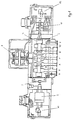
- the 4-way continuous flow valve 1 has a valve housing 6 with a central pressure inlet channel P, two axially offset pressure outlet channels A, B and two return channels T, T2, which are connected to the supply tank.
- a control piston 7 is mounted in the valve housing 6, the two end faces of which are acted upon by a control pressure of the pilot control stage 8 in the axial direction.
- the control piston 7 is designed such that the pressure outlet channels A, B have a 20% coverage compared to the central pressure inlet channel P. In contrast, there is a 15% shortage between the pressure outlet channels A, B and the return channels T, T2.
- the continuous flow valve includes a shuttle valve 9, which is connected on the inlet side to the chambers, pressure outflow channels A, B. On the output side, the shuttle valve 9 is connected to the pressure sensor 2.
- This converter element is in turn connected on the output side to the pressure limiting regulator 10.
- the control piston 7 has an extension on one of its end faces, which is in the inductive Position sensor 11 protrudes.
- the inductive position sensor feeds its output signal into the position controller 12 integrated in the valve.
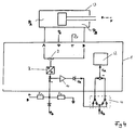
- FIG. 2 shows a schematic representation of a consumer, for example a differential cylinder 13 and proportional proportional valve 1.
- the differential cylinder has a piston which can be loaded with a force F and has the cross-sectional areas A K and A R.
- the piston divides the differential cylinder 13 into two chambers, each of which is connected to the pressure outlet channels A, B of the four-way proportional pilot valve.
- the pressure in the two chambers is fed as an electrical signal via the shuttle valve 9 and the integrated pressure sensor 2 into the pressure limiting regulator 10.
- the pressure limiting controller 10 also receives the pressure limit value P G on the input side.
- the circuit 3 is connected on the input side to the output of the pressure limiting regulator via a diode which is polarized for a positive signal in the flow direction and additionally receives the desired flow signal Q S.
- the output side supplies the signal U A , which is fed into the position controller 12.
- FIG. 3 shows a preferred embodiment of the correction circuit according to the invention.
- the correction circuit 3 comprises two switching paths 4, 5, both of which receive the desired flow signal Q S and the correction signal U K on the input side.
- the switching path 4 comprises an operational amplifier A1c. Its inverting input is connected to the two input terminals of the correction circuit 3 via the resistors R5 and R11.
- the output of the operational amplifier A1c is via the diode D3 which is polarized in the reverse direction with respect to a positive polarity inverting input connected.
- the output is also via the diode D4, which is connected with respect to a positive polarity in the flow direction and the resistor R8 fed back to the inverting input of the operational amplifier.
- the non-inverting input of the operational amplifier is connected to a reference potential.
- the switching path 5 comprises two operational amplifiers A1d and A1a in series connection.
- the inverting input of the operational amplifier A1d is connected to the input terminal U K via the resistor R10. Its output signal is fed back through resistor R9 to the inverting input.
- the non-inverting input is connected to a reference potential.
- the output signal of operational amplifier A1d is connected via resistor R4 to the inverting input of operational amplifier A1a.
- the input terminal Q S feeds through the resistor R3 into the inverting input of the operational amplifier A1a.
- the output of the operational amplifier A1a has in its forward branch a diode D2 which is connected in the direction of flow with respect to a negative polarity. The output signal is fed back via the diode D1 and the resistor R7 to the inverting input of the operational amplifier.
- the non-inverting input of operational amplifier A1a is connected to a reference potential.
- the two outputs of the switching paths 4 and 5 are connected to the inverting input of the operational amplifier A1b via the resistors R6 and R2.
- the non-inverting input of the operational amplifier is connected to a reference potential.
- the exit of the Operational amplifier U A is connected via resistor R1 to the inverting input of the operational amplifier.
- Figure 4 shows a schematic representation of the signal flow diagram of the flow continuous valve with a circuit according to the prior art.
- the connection of the differential cylinder 13 with the shuttle valve 9 and the integrated pressure sensor 2 is identical to that described in FIG.
- the pressure limiting controller 10 is connected on the input side via a diode to the input terminal P G for the pressure limit value.
- the input of the pressure limiting regulator has a connection to a voltage divider circuit, consisting of two resistors, one connection being connected to the positive supply voltage, the other connected to the reference potential and the central connection to the pressure limiting regulator.
- the output of the pressure limiting regulator 10 is connected in the forward branch to the input of a two-pole relay 14 via a diode which is polarized in the forward direction.
- the other input of the relay is connected to the input terminal Q S for the desired flow signal.
- the two outputs of the relay 14 are connected to the input side of the position controller 12 via a subtracting device.
- the pressure outlet channel A of the valve is connected to the pressure inlet channel P with a positive output signal U A of the circuit 3.
- the pressure P A is greater than the pressure P B and therefore acts on the pressure transducer 2 via the shuttle valve 9.
- the pressure limiting controller If the pressure P A assumes a higher pressure than the pressure limit value specified by the signal P G due to an external force F> O, the pressure limiting controller outputs a positive correction signal U K to the correction circuit 3 from.
- the switching path 4 does not provide an output signal, while the switching path 5 emits at its output a signal Q S which is correct in terms of the sign by U K.
- This output signal acts on the position control loop 12 of the control piston.
- the opening between the pressure outlet channel A and the pressure inlet channel P decreases and the pressure P A in the working chamber decreases.
- the peculiarity of the circuit according to the present invention is that even if a correction signal U K from the pressure limiting controller 10 is greater in magnitude than the positive setpoint signal Q S, a positive output signal U A can at most be reduced to zero, but not a negative one Assumes value.
- the force when retracting the differential cylinder is limited in an analogous manner.
- the pressure P B acts on the pressure transducer 2 via the shuttle valve 9. If the signal Q S is negative, the switching path 5 does not provide an output signal, while the switching path 4 emits a signal at its output, the amount of which is reduced by the value of U K. By decreasing the amount of the flow target signal Q S , the opening between the pressure outlet signal B and the pressure inlet signal P is reduced. In analogy to the process in which the cylinder extends, the negative setpoint signal Q S is reduced in magnitude to a maximum of zero. However, a change of sign is excluded.
Landscapes
- Physics & Mathematics (AREA)
- Fluid Mechanics (AREA)
- General Physics & Mathematics (AREA)
- Engineering & Computer Science (AREA)
- Automation & Control Theory (AREA)
- Fluid-Pressure Circuits (AREA)
Description
- Die Erfindung bezieht sich auf ein 4-Wege-Durchflußstetigventil nach dem Oberbegriff des Anspruches 1.
- Aus dem Stand der Technik sind Proportional-Stetig (P/Q)-Ventile in 3-Wege-Ausführung bekannt. Diese Ventile regeln einen Druck oder eine Ventildurchflußmenge in einem Verbraucher (Last) in Abhängigkeit von einem vom Anwender vorgegebenen analogen Sollsignal. Der Ventildurchfluß ist durch die Stellung eines Steuerkolbens bestimmt, die mit Hilfe eines elektronischen Lageregelkreises geregelt ist. Hierzu vergleicht der im Ventil integrierte Lageregler den durch den Lageaufnehmer erfaßten Istwert der Steuerschieberstellung mit einem Sollwertsignal. Bei Soll-Istwert-Abweichungen gibt der integrierte Lageregler Stellsignale an die Vorsteuerstufe ab, die dem Lagefehler des Steuerschiebers entgegenwirken. Weiter enthält das Durchflußventil einen Druckaufnehmer und einen Druckbegrenzungsregler. Dieser Druckbegrenzungsregler vergleicht den Druck zum Ausfahren des Zylinders im Druckauslaßkanal mit einem externen Druckgrenzwert. Überschreitet das Ausgangssignal des Druckaufnehmers den Druckgrenzwert, so gibt der Druckbegrenzungsregler ein Korrektursignal zur Verringerung des Sollwertsignals ab. Mit dieser Anordnung kann die Geschwindigkeit des Zylinders gesteuert werden, wobei der Druckbegrenzungsregler dafür sorgt, daß der Druck im Druckauslaßkanal einen bestimmten Wert (Druckgrenze) nicht überschreitet, und somit die Kraft des Zylinders begrenzt wird. Nachteilig bei dieser Ausführung ist jedoch, daß beim Einfahren des Zylinders die Kraft nicht begrenzt wird.
- Weiter sind aus dem Stand der Technik P/Q-Ventile gemäß der Figur 4 als 4-Wege-Ventile mit zwei Anschlüssen A und B zum Ein- und Ausfahren des Zylinders bekannt. Über ein Wechselventil ist der Druckaufnehmer mit den Anschlüssen A und B des Ventiles verbunden. Der Druckaufnehmer mißt immer den höheren Druck der beiden Drücke PA bzw. PB in den Kammern, die mit den entsprechenden Anschlüssen verbunden sind.
- Der Druckbegrenzungsregler 10 ist eingangsseitig über eine Diode mit der Eingangsklemme PG für den Druckgrenzwert verbunden. Zusätzlich weist der Eingang des Druckbegrenzungsreglers 10 eine Verbindung zu einer Spannungsteilerschaltung auf, bestehend aus zwei Widerständen RX und RY, wobei der Widerstand RX mit der positiven Versorgungsspannung, der Widerstand RY mit dem Bezugspotential und der mittige Anschluß mit dem Druckbegrenzungsregler verbunden ist. Der Ausgang UK des Druckbegrenzungsreglers 10 ist im Vorwärtszweig über eine in Flußrichtung gepolte Diode mit dem Eingang eines zweipoligen Relais 14 verbunden. Der andere Eingang des Relais 14 ist mit der Eingangsklemme QS für das Durchfluß-Sollsignal verbunden. Die beiden Ausgänge des Relais 14 liefern mit der Subtrahiereinrichtung das Signal UA, das eingangsseitig in den Lageregler 12 geführt ist.
- Der Zylinder (13) fährt durch ein Signal UA positiver Polarität aus und durch ein Signal UA negativer Polarität wieder ein. Zur Erzeugung eines positiven Signals UA subtrahiert der Differenzverstärker das Korrektursignal UK vom Q-Soll-Signal. Zur Erzeugung des negativen Signales UA werden die beiden Eingänge Q-Soll und Korrektursignal UK des subtrahierenden Differenzverstärkers miteinander vertauscht. Dies geschieht durch Betätigung des zweipoligen Umschaltrelais 14 bei einem beabsichtigten Wechsel der Bewegungsrichtung des Zylinders (13). Nachteilig bei dieser Ausführung ist jedoch die zusätzlich erforderliche Steuerleitung zum Umschalten des Relais 14. Weiter ist es notwendig, den Druckgrenzwert über ein externes elektrisches Netzwerk auf einen unteren Mindestwert zu begrenzen. Ohne die Begrenzung kann das Korrektursignal UK einen größeren Wert als das Q-Soll-Signal annehmen. Dadurch wechselt das Signal UA unzulässigerweise seine Polarität, was zu einer Fehlfunktion des Steuerkolbens 7 führt.
- Der Erfindung liegt die Aufgabe zugrunde, ein 4-Wege-Durchflußstetigventil der eingangs genannten Art anzugeben, das einfach aufgebaut ist.
- Diese Aufgabe wird, gemäß vorliegender Erfindung durch die Merkmale des Anspruches 1 gelöst.
- Die beiden Schaltstrecken sind derart ausgebildet, daß sie an ihrem Ausgang kein Signal liefern, wenn das Korrektursignal UK größer ist als der Betrag des Sollwerts QS. Weiterhin ist stets nur eine der beiden Schaltstrecken bei einer bestimmten Polarität aktiv, während die andere kein Ausgangssignal erzeugt. Dadurch stimmt die Polarität des Ausgangssignals des elektrischen Schaltkreises immer mit der Polarität des Eingangssollsignals überein und der Betrag des Ausgangssignals ist maximal auf den Wert Null verringert. Dem Anwender steht ein voll abgeglichenes kalibriertes Durchflußregelventil zur Verfügung, das Eingangssollwerte positiver und negativer Polarität in eine Steuerbewegung für den Steuerkolben umsetzt. Eine Fehlfunktion des Steuerkolbens durch einen unzulässigen Polaritätswechsel ist dabei ausgeschlossen. Die im Stand der Technik benötigten Schaltmittel und externen Beschaltungen sind nicht erforderlich.
- Gemäß einer bevorzugten Ausführungsform beinhalten die elektrischen Schaltstrecken zum Erzeugen des Ausgangssignals wenigstens einen mit negativer Rückkopplung versehenen Operationsverstärker. Die Operationsverstärker realisieren in Analogtechnik die Addition der Eingangssignale bzw. die Subtraktion durch eine Addition eines invertierten Signals mit einem nichtinvertierten Signal.
- Gemäß einer Weiterbildung weisen die Operationsverstärker der beiden Schaltstrecken im Rückkopplungszweig eine Diode auf, die derart gepolt ist, daß die gesamte Teilstrecke nur für eine Polarität aktiv ist. Für die eine Polarität ist der Ausgang des Operationsverstärkers mit dem Eingang kurzgeschlossen, so daß die Schaltstrecke kein Ausgangssignal für diese Polarität liefert. Für die andere Polarität ist der Operationsverstärker in herkömmlicher Weise mit einem verstärkenden Rückkopplungselement versehen.
- Günstigerweise enthalten die beiden Schaltstrecken im Vorwärtszweig jeweils eine Diode, die derart gepolt ist, daß die gesamte Schaltstrecke nur für eine Polarität ein Ausgangssignal liefert.
- Gemäß einer bevorzugten Ausführungsform weist der Steuerkolben einen speziellen Steuerkantenschnitt mit einer Überdeckung zwischen den Anschlüssen A, B und dem Betriebsdruckanschluß P in einem Bereich von 20-30 %, vorzugsweise 20 % und mit einer Unterdeckung zwischen den Anschlüssen A, B und dem Ausgleichsbehälter T in einem Bereich von 15 bis 25 %, vorzugsweise 15 % auf. Dieser Weiterbildung liegt die Erkenntnis zugrunde, daß der spezielle Steuerkantenschnitt eine Abhängigkeit der Drücke in den Kammern des Arbeitszylinders vom Ansteuersignal des Steuerkolbens bewirkt. Diese Abhängigkeit besteht bei einem symmetrischen Nullschnittventil nicht, vielmehr steht der Kammerdruck des Arbeitszylinders in einem konstanten Verhältnis zum Betriebsdruck. Bei einem Steuerkolben mit Steuerkantenschnitt ist der Druck in den Kammern des Arbeitszylinders bei einem kleinen Ansteuersignal entsprechend geringer. Mit der Schaltung nach der Erfindung ist es möglich, mit einem Druckgrenzwert zu arbeiten, der noch unterhalb dem unteren Grenzwert liegt, der durch die externe Schaltung nach dem Stand der Technik erzeugt wird. Die Arbeitsweise mit einem so geringen Druckgrenzwert wäre jedoch bei der Schaltung nach dem Stand der Technik aus Sicherheitsgründen nicht zulässig.
- Gemäß einer bevorzugten Ausführungsform ist der elektrische Schaltkreis in dem Ventilgehäuse integriert. Bei der Korrekturschaltung gemäß der Erfindung werden nur diskrete, einfach auf einer gedruckten Schaltplatte montierbare Bauteile verwendet. Da keine externe Beschaltung und keine Relais verwendet werden, läßt sich die gesamte Elektronik auf einfacheWeise in dem Ventil integrieren.
- Im folgenden wird die Erfindung anhand einer in den Zeichnungen dargestellten Ausführungsform erläutert. Es zeigen:
- Figur 1
- ein Schnittbild durch das 4-Wege-Durchflußstetigventil;
- Figur 2
- in einer schematischen Darstellung den Signalflußplan des Ventils mit der Korrekturschaltung gemäß der Erfindung;
- Figur 3
- eine bevorzugte Ausführungsform der Korrekturschaltung;
- Figur 4
- in einer schematischen Darstellung den Signalflußplan des Ventils mit einer Schaltung gemäß dem Stand der Technik.
- Das 4-Wege-Durchflußstetigventil 1 weist ein Ventilgehäuse 6 mit einem mittigen Druckeinlaßkanal P, zwei in axialer Richtung versetzt angeordnete Druckauslaßkanäle A, B und zwei Rückführkanäle T, T2, die mit dem Versorgungstank verbunden sind, auf. In dem Ventilgehäuse 6 ist ein Steuerkolben 7 gelagert, dessen zwei Stirnflächen mit einem Steuerdruck der Vorsteuerstufe 8 in axialer Richtung beaufschlagt werden. Der Steuerkolben 7 ist so ausgebildet, daß die Druckauslaßkanäle A, B gegenüber dem mittigen Druckeinlaßkanal P eine 20%ige Überdeckung aufweisen. Zwischen den Druckauslaßkanälen A, B und den Rückführkanälen T, T2, dagegen besteht eine 15 %ige Unterdeckung. Das Durchfluß-Stetigventil beinhaltet ein Wechselventil 9, das eingangsseitig mit den Kammern, Druckausflußkanäle A, B verbunden ist. Ausgangsseitig ist das Wechselventil 9 mit dem Druckaufnehmer 2 verbunden. Dieses Wandlerelement ist wiederum ausgangsseitig mit dem Druckbegrenzungsregler 10 verbunden. Der Steuerkolben 7 besitzt an einer seiner Stirnflächen eine Verlängerung, die in den induktiven Lageaufnehmer 11 hineinragt. Der induktive Lageaufnehmer speist sein Ausgangssignal in den im Ventil integrierten Lageregler 12 ein.
- In Figur 2 ist in einer schematischen Darstellung ein Verbraucher, beispielsweise ein Differentialzylinder 13 und das Proportional-Stetigventil 1 dargestellt. Der Differentialzylinder weist einen mit einer Kraft F belastbaren Kolben mit den Querschnittsflächen AK und AR auf. Der Kolben teilt den Differentialzylinder 13 in zwei Kammern, die jeweils mit den Druckauslaßkanälen A, B des Vierwege-Proportional-Stetigventils verbunden sind. Der Druck in den beiden Kammern wird über das Wechselventil 9 und dem integrierten Druckaufnehmer 2 in den Druckbegrenzungsregler 10 als elektrisches Signal eingespeist. Weiter erhält der Druckbegrenzungsregler 10 eingangsseitig den Druckgrenzwert PG. Der Schaltkreis 3 gemäß der vorliegenden Erfindung ist eingangsseitig über eine für ein positives Signal in Flußrichtung gepolte Diode mit dem Ausgang des Druckbegrenzungsreglers verbunden und erhält zusätzlich das Durchfluß-Sollsignal QS. Die Ausgangsseite liefert das Signal UA, das in den Lageregler 12 eingespeist wird.
- Figur 3 zeigt eine bevorzugte Ausführungsform der Korrekturschaltung gemäß der Erfindung. Die Korrekturschaltung 3 umfaßt zwei Schaltstrecken 4,5, die beide eingangsseitig das Durchfluß-Sollsignal QS und das Korrektursignal UK erhalten. Die Schaltstrecke 4 umfaßt einen Operationsverstärker A1c. Sein invertierender Eingang ist über die Widerstände R5 und R11 mit den beiden Eingangsklemmen der Korrekturschaltung 3 verbunden. Der Ausgang des Operationsverstärkers A1c ist über die Diode D3 die in bezug auf eine positive Polarität in Sperrichtung gepolt ist, mit dem invertierenden Eingang verbunden. Der Ausgang ist weiterhin über die Diode D4, die in bezug auf eine positive Polariät in Flußrichtung geschaltet ist und den Widerstand R8 auf den invertierenden Eingang des Operationsverstärkers rückgekoppelt. Der nichtinvertierende Eingang des Operationsverstärkers ist auf ein Bezugspotential gelegt.
- Die Schaltstrecke 5 umfaßt zwei Operationsverstärker A1d und A1a in Serienschaltung. Der invertierende Eingang des Operationsverstärkers A1d ist über den Widerstand R10 mit der Eingangsklemme UK verbunden. Sein Ausgangssignal ist über den Widerstand R9 auf den invertierenden Eingang rückgekoppelt. Der nicht invertierende Eingang ist auf ein Bezugspotential gelegt. Das Ausgangssignal des Operationsverstärkers A1d ist über den Widerstand R4 mit dem invertierenden Eingang des Operationsverstärkers A1a verbunden. Zusätzlich speist die Eingangsklemme QS über den Widerstand R3 in den invertierenden Eingang des Operationsverstärkers A1a ein. Der Ausgang des Operationsverstärkers A1a weist in seinem Vorwärtszweig eine Diode D2 auf, die in bezug auf eine negative Polarität in Flußrichtung geschaltet ist. Das Ausgangssignal ist über die Diode D1 und den Widerstand R7 auf den invertierenden Eingang des Operationsverstärkers rückgekoppelt. Der nichtinvertierende Eingang des Operationsverstärkers A1a ist auf ein Bezugspotential gelegt.
- Die beiden Ausgänge der Schaltstrecken 4 und 5 sind über die Widerstände R6 und R2 mit dem invertierenden Eingang des Operationsverstärkers A1b verbunden. Der nichtinvertierende Eingang des Operationsverstärkers ist auf ein Bezugspotential gelegt. Der Ausgang des Operationsverstärkers UA ist über den Widerstand R1 mit dem invertierenden Eingang des Operationsverstärkers verbunden.
- Figur 4 zeigt in einer schematischen Darstellung den Signalflußplan des Durchfluß-Stetigventils mit einer Schaltung gemäß dem Stand der Technik. Der Anschluß des Differentialzylinders 13 mit dem Wechselventil 9 und dem integrierten Druckaufnehmer 2 ist identisch mit dem in der Figur 2 beschriebenen. Der Druckbegrenzungsregler 10 ist eingangsseitig über eine Diode mit der Eingangsklemme PG für den Druckgrenzwert verbunden. Zusätzlich weist der Eingang des Druckbegrenzungsreglers eine Verbindung zu einer Spannungsteilerschaltung auf, bestehend aus zwei Widerständen, wobei der eine Anschluß mit der positiven Versorgungsspannung verbunden ist, der andere mit dem Bezugspotential und der mittige Anschluß mit dem Druckbegrenzungsregler. Der Ausgang des Druckbegrenzungsreglers 10 ist im Vorwärtszweig über eine in Flußrichtung gepolte Diode mit dem Eingang eines zweipoligen Relais 14 verbunden. Der andere Eingang des Relais ist mit der Eingangsklemme QS für das Durchfluß-Sollsignal verbunden. Die beiden Ausgänge des Relais 14 sind über eine Subtrahiereinrichtung mit der Eingangsseite des Lagereglers 12 verbunden. Abschließend soll die Funktions- und Wirkungsweise der Korrekturschaltung für das 4-Wege-Durchfluß-Stetigventil erläutert werden.
- Bei Beginn eines Regelvorgangs wird bei einem positiven Ausgangssignal UA der Schaltung 3 der Druckauslaßkanal A des Ventils mit dem Druckeinlaßkanal P verbunden. Dadurch entsteht in der mit dem Anschluß A verbundenen Arbeitskammer der Druck PA wodurch der Zylinder ausfährt. Der Druck PA ist größer als der Druck PB und wirkt daher über das Wechselventil 9 auf den Druckaufnehmer 2. Nimmt durch eine externe Kraft F>O der Druck PA einen höheren Druck an als der durch das Signal PG vorgegebene Druckgrenzwert, so gibt der Druckbegrenzungsregler ein positives Korrektursignal UK an die Korrekturschaltung 3 ab. Bei einem positiven Signal QS liefert die Schaltstrecke 4 kein Ausgangssignal, während die Schaltstrecke 5 an ihrem Ausgang ein um den Betrag von UK vermindertes vorzeichenrichtiges Signal QS abgibt. Dieses Ausgangssignal wirkt auf den Lageregelkreis 12 des Steuerkolbens. Infolgedessen verringert sich die Öffnung zwischen dem Druckauslaßkanal A und dem Druckeinlaßkanal P und vermindert den Druck PA in der Arbeitskammer. Die Besonderheit der Schaltung nach der vorliegenden Erfindung liegt darin, daß selbst wenn ein Korrektursignal UK vom Druckbegrenzungsregler 10 dem Betrage nach größer ist als das positive Sollwertsignal QS ein positives Ausgangssignal UA höchstens auf den Wert Null verringert werden kann, nicht jedoch einen negativen Wert annimmt.
- In analoger Weise wird die Kraft beim Einfahren des Differentialzylinders begrenzt. Der Druck PB wirkt über das Wechselventil 9 auf den Druckaufnehmer 2. Bei einem negativen Signal QS liefert die Schaltstrecke 5 kein Ausgangssignal, während die Schaltstrecke 4 an ihrem Ausgang ein Signal abgibt, dessen Betrag um den Wert von UK vermindert ist. Durch das Verringern des Betrags des Durchfluß-Sollsignals QS wird die Öffnung zwischen dem Druckauslaßsignal B und dem Druckeinlaßsignal P verringert. In Analogie zu dem Vorgang bei dem der Zylinder ausfährt, wird das negative Sollwertsignal QS dem Betrage nach höchstens auf den Wert Null verringert. Ein Vorzeichenwechsel ist jedoch ausgeschlossen.
Claims (6)
- 4-Wege-Durchflußstetigventil (1) mit einem Steuerkolben (7), mit einem integrierten Druckaufnehmer (2) und einem elektrischen Lageregelkreis nach einem elektrischen Schaltkreis (3) zum Erzeugen eines Korrektursignales (UK), das den Betrag des eingestellten Durchflußsollsignales (QS) dann verringert, wenn der durch den Druckaufnehmer (2) festgestellte Druck einen vorgegebenen Druckgrenzwert (PG) überschreitet,
dadurch gekennzeichnet,
daß der elektrische Schaltkreis (3) zwei zueinander parallel geschaltete Schaltstrecken (4, 5) aufweist, die beide eingangsseitig das Korrektursignal (UK) und das Sollsignal (QS) erhalten, wobei die beiden Schaltstrecken (4, 5) so ausgebildet sind, daß sie kein Ausgangssignal (UA) liefern, wenn das Korrektursignal (UK) größer als der Betrag des Sollsignales (QS) ist;
daß die erste Schaltstrecke (4) derart ausgebildet ist, daß sie an ihrem Ausgang dann kein Ausgangssignal liefert, wenn das Sollsignal (QS) positive Polarität aufweist;
daß die zweite Schaltstrecke (5) derart ausgebildet ist, daß sie an ihrem Ausgang dann kein Ausgangssignal liefert, wenn das Sollsignal (QS) negative Polarität aufweist; und daß die beiden Schaltstrecken (4, 5) ferner derart ausgebildet sind, daß sie ein Ausgangssignal (UA) liefern, das der folgenden Gleichung genügt:

UA = Ausgangssignal, sgn = Signum, UK = Korrektursignal, QS = Durchflußsollsignal. - 4-Wege-Durchflußstetigventil nach Anspruch 1,
dadurch gekennzeichnet,
daß die elektrischen Schaltstrecken (4, 5) zum Erzeugen des Ausgangssignales (UA) wenigstens einen mit negativer Rückkopplung versehenen Operationsverstärker (A1a, A1b, A1c, A1d) beinhalten. - 4-Wege-Durchflußstetigventil nach Anspruch 1 oder 2,
dadurch gekennzeichnet,
daß die beiden Schaltstrecken (4, 5) jeweils wenigstens einen Operationsverstärker (A1a, A1b, A1c, A1d) enthalten, der im Rückkopplungszweig eine Diode (D1, D3) aufweist, die derart gepolt ist, daß die gesamte Schaltstrecke nur für eine Polarität aktiv ist. - 4-Wege-Durchflußstetigventil nach wenigstens einem der Ansprüche 1 bis 3,
dadurch gekennzeichnet,
daß die beiden Schaltstrecken (4, 5) im Vorwärtszweig jeweils eine Diode (D2, D4) enthalten, die derart gepolt ist, daß die gesamte Schaltstrecke nur für eine Polarität ein Ausgangssignal liefert. - 4-Wege-Durchflußstetigventil nach wenigstens einem der Ansprüche 1 bis 4,
dadurch gekennzeichnet,
daß der Steuerkolben einen speziellen Steuerkantenschnitt mit einer Überdeckung zwischen den Anschlüssen (A, B) und dem Betriebsdruckanschluß (P) in einem Bereich von 20-30 %, vorzugsweise 20 % und mit einer Unterdeckung zwischen den Anschlüssen (A, B) und dem Ausgleichsbehälter (T) in einen Bereich von 5-25 %, vorzugsweise 15 % aufweist. - 4-Wege-Durchflußstetigventil nach wenigstens einem der Ansprüche 1 bis 5,
dadurch gekennzeichnet,
daß der elektrische Schaltkreis (3) in das Ventilgehäuse integriert ist.
Priority Applications (4)
| Application Number | Priority Date | Filing Date | Title |
|---|---|---|---|
| DE59106483T DE59106483D1 (de) | 1991-02-27 | 1991-02-27 | Korrekturschaltung für 4-Wege-Durchflussstetigventil. |
| EP91102931A EP0500986B1 (de) | 1991-02-27 | 1991-02-27 | Korrekturschaltung für 4-Wege-Durchflussstetigventil |
| PCT/EP1992/000416 WO1992015928A1 (de) | 1991-02-27 | 1992-02-27 | Korrekturschaltung für 4-wege-durchflussstetigventil |
| JP92504943A JPH05507379A (ja) | 1991-02-27 | 1992-02-27 | 四方型連続流量弁用補正回路 |
Applications Claiming Priority (1)
| Application Number | Priority Date | Filing Date | Title |
|---|---|---|---|
| EP91102931A EP0500986B1 (de) | 1991-02-27 | 1991-02-27 | Korrekturschaltung für 4-Wege-Durchflussstetigventil |
Publications (2)
| Publication Number | Publication Date |
|---|---|
| EP0500986A1 EP0500986A1 (de) | 1992-09-02 |
| EP0500986B1 true EP0500986B1 (de) | 1995-09-13 |
Family
ID=8206461
Family Applications (1)
| Application Number | Title | Priority Date | Filing Date |
|---|---|---|---|
| EP91102931A Expired - Lifetime EP0500986B1 (de) | 1991-02-27 | 1991-02-27 | Korrekturschaltung für 4-Wege-Durchflussstetigventil |
Country Status (4)
| Country | Link |
|---|---|
| EP (1) | EP0500986B1 (de) |
| JP (1) | JPH05507379A (de) |
| DE (1) | DE59106483D1 (de) |
| WO (1) | WO1992015928A1 (de) |
Families Citing this family (1)
| Publication number | Priority date | Publication date | Assignee | Title |
|---|---|---|---|---|
| IT1265319B1 (it) * | 1993-12-22 | 1996-10-31 | Nuovo Pignone Spa | Sistema perfezionato di comando dell'attuatore di una valvola pneumatica |
Family Cites Families (2)
| Publication number | Priority date | Publication date | Assignee | Title |
|---|---|---|---|---|
| US4886422A (en) * | 1987-07-09 | 1989-12-12 | Tokyo Keiki Company Ltd. | Control apparatus of variable delivery pump |
| DE3829992A1 (de) * | 1988-09-03 | 1990-03-15 | Bosch Gmbh Robert | Proportionalventil |
-
1991
- 1991-02-27 EP EP91102931A patent/EP0500986B1/de not_active Expired - Lifetime
- 1991-02-27 DE DE59106483T patent/DE59106483D1/de not_active Expired - Fee Related
-
1992
- 1992-02-27 WO PCT/EP1992/000416 patent/WO1992015928A1/de unknown
- 1992-02-27 JP JP92504943A patent/JPH05507379A/ja active Pending
Also Published As
| Publication number | Publication date |
|---|---|
| WO1992015928A1 (de) | 1992-09-17 |
| DE59106483D1 (de) | 1995-10-19 |
| JPH05507379A (ja) | 1993-10-21 |
| EP0500986A1 (de) | 1992-09-02 |
Similar Documents
| Publication | Publication Date | Title |
|---|---|---|
| DE2447858C3 (de) | Servo-Ventileinrichtung | |
| DE2811345C2 (de) | Druckregler für pneumatische Drücke, insbesondere in Fahrzeugen | |
| EP0091018B1 (de) | Positionsregelung für einen doppelt wirkenden hydraulischen Motor | |
| EP0546300B1 (de) | Elektrohydraulische Steuereinrichtung | |
| EP0275968A2 (de) | Steuervorrichtung für ein hydrostatisches Getriebe für wenigstens zwei Verbraucher | |
| EP0357964B1 (de) | Proportionalventil | |
| DE102019217068A1 (de) | Ventilmodulanordnung | |
| DE3420674C2 (de) | Druckversorgungseinrichtung für ein Hydrauliksystem | |
| DE2751254C2 (de) | ||
| EP0500986B1 (de) | Korrekturschaltung für 4-Wege-Durchflussstetigventil | |
| EP0822344A2 (de) | Pneumatischer Regelantrieb sowie Verblockventil für einen derartigen pneumatischen Regelantrieb | |
| EP0055351B1 (de) | Elektrohydraulischer Stellantrieb für Turbinenventile | |
| DE3013853A1 (de) | Hydraulikanlage, insbesondere fuer kraftfahrzeuge | |
| EP0092064B1 (de) | Vorrichtung zum Betätigen eines Schiebekörpers, insbesondere des Kolbenschiebers eines Wegeventils | |
| DE2822709A1 (de) | Kombiniertes rueckkopplungsregelungssystem | |
| DE102005045035B4 (de) | Hydraulische Schaltungsanordnung zur Versorgung eines doppelt wirkenden hydraulischen Verbrauchers | |
| EP0582099A2 (de) | Hydrauliksystem mit Lastmeldung | |
| DE2255461C2 (de) | Elektro-hydraulische Stellgliedanordnung | |
| DE3738241A1 (de) | Elektrohydraulische vorrichtung zur lastunabhaengigen regelung eines volumenstromes proportional zu einem eingangssignal | |
| EP0729083A1 (de) | Doppelwirkender elektropneumatischer Stellungsregler | |
| EP0044518A1 (de) | Vorrichtung zur Regelung einer Verstellpumpe | |
| DE1525690A1 (de) | Summierungsvorrichtung fuer Arbeitsmittelsignale | |
| DE4041033C2 (de) | ||
| DE2253457A1 (de) | Vorrichtung fuer die verarbeitung eines fluidiksignales | |
| EP1264109A1 (de) | Einrichtung zur steuerung eines hydraulischen aktuators |
Legal Events
| Date | Code | Title | Description |
|---|---|---|---|
| PUAI | Public reference made under article 153(3) epc to a published international application that has entered the european phase |
Free format text: ORIGINAL CODE: 0009012 |
|
| AK | Designated contracting states |
Kind code of ref document: A1 Designated state(s): AT BE CH DE DK ES FR GB GR IT LI LU NL SE |
|
| RBV | Designated contracting states (corrected) |
Designated state(s): DE GB IT |
|
| 17P | Request for examination filed |
Effective date: 19930301 |
|
| 17Q | First examination report despatched |
Effective date: 19941026 |
|
| GRAA | (expected) grant |
Free format text: ORIGINAL CODE: 0009210 |
|
| AK | Designated contracting states |
Kind code of ref document: B1 Designated state(s): DE GB IT |
|
| PG25 | Lapsed in a contracting state [announced via postgrant information from national office to epo] |
Ref country code: IT Free format text: LAPSE BECAUSE OF FAILURE TO SUBMIT A TRANSLATION OF THE DESCRIPTION OR TO PAY THE FEE WITHIN THE PRE;WARNING: LAPSES OF ITALIAN PATENTS WITH EFFECTIVE DATE BEFORE 2007 MAY HAVE OCCURRED AT ANY TIME BEFORE 2007. THE CORRECT EFFECTIVE DATE MAY BE DIFFERENT FROM THE ONE RECORDED.SCRIBED TIME-LIMIT Effective date: 19950913 |
|
| REF | Corresponds to: |
Ref document number: 59106483 Country of ref document: DE Date of ref document: 19951019 |
|
| GBT | Gb: translation of ep patent filed (gb section 77(6)(a)/1977) |
Effective date: 19950929 |
|
| PLBE | No opposition filed within time limit |
Free format text: ORIGINAL CODE: 0009261 |
|
| STAA | Information on the status of an ep patent application or granted ep patent |
Free format text: STATUS: NO OPPOSITION FILED WITHIN TIME LIMIT |
|
| 26N | No opposition filed | ||
| REG | Reference to a national code |
Ref country code: GB Ref legal event code: IF02 |
|
| PGFP | Annual fee paid to national office [announced via postgrant information from national office to epo] |
Ref country code: GB Payment date: 20060208 Year of fee payment: 16 |
|
| PGFP | Annual fee paid to national office [announced via postgrant information from national office to epo] |
Ref country code: DE Payment date: 20060330 Year of fee payment: 16 |
|
| GBPC | Gb: european patent ceased through non-payment of renewal fee |
Effective date: 20070227 |
|
| PG25 | Lapsed in a contracting state [announced via postgrant information from national office to epo] |
Ref country code: DE Free format text: LAPSE BECAUSE OF NON-PAYMENT OF DUE FEES Effective date: 20070901 |
|
| PG25 | Lapsed in a contracting state [announced via postgrant information from national office to epo] |
Ref country code: GB Free format text: LAPSE BECAUSE OF NON-PAYMENT OF DUE FEES Effective date: 20070227 |