EP0500550B1 - Sectionneur pour appareillages haute tension sous blindage metallique avec isolation par gaz comprime - Google Patents
Sectionneur pour appareillages haute tension sous blindage metallique avec isolation par gaz comprime Download PDFInfo
- Publication number
- EP0500550B1 EP0500550B1 EP90914126A EP90914126A EP0500550B1 EP 0500550 B1 EP0500550 B1 EP 0500550B1 EP 90914126 A EP90914126 A EP 90914126A EP 90914126 A EP90914126 A EP 90914126A EP 0500550 B1 EP0500550 B1 EP 0500550B1
- Authority
- EP
- European Patent Office
- Prior art keywords
- contact pin
- switching pin
- spring
- isolating switch
- main contact
- Prior art date
- Legal status (The legal status is an assumption and is not a legal conclusion. Google has not performed a legal analysis and makes no representation as to the accuracy of the status listed.)
- Expired - Lifetime
Links
- 230000001133 acceleration Effects 0.000 claims description 6
- 230000000284 resting effect Effects 0.000 claims description 5
- 238000010276 construction Methods 0.000 claims description 2
- 230000013011 mating Effects 0.000 abstract description 15
- 230000007935 neutral effect Effects 0.000 abstract 1
- 230000006835 compression Effects 0.000 description 9
- 238000007906 compression Methods 0.000 description 9
- 230000000903 blocking effect Effects 0.000 description 5
- 238000005538 encapsulation Methods 0.000 description 3
- 230000001960 triggered effect Effects 0.000 description 3
- 230000001681 protective effect Effects 0.000 description 2
- 238000000926 separation method Methods 0.000 description 2
- 230000005684 electric field Effects 0.000 description 1
- 239000011810 insulating material Substances 0.000 description 1
- 239000000463 material Substances 0.000 description 1
- 230000002040 relaxant effect Effects 0.000 description 1
- 238000005096 rolling process Methods 0.000 description 1
Images


Classifications
-
- H—ELECTRICITY
- H01—ELECTRIC ELEMENTS
- H01H—ELECTRIC SWITCHES; RELAYS; SELECTORS; EMERGENCY PROTECTIVE DEVICES
- H01H33/00—High-tension or heavy-current switches with arc-extinguishing or arc-preventing means
- H01H33/02—Details
- H01H33/04—Means for extinguishing or preventing arc between current-carrying parts
- H01H33/12—Auxiliary contacts on to which the arc is transferred from the main contacts
- H01H33/121—Load break switches
- H01H33/122—Load break switches both breaker and sectionaliser being enclosed, e.g. in SF6-filled container
-
- H—ELECTRICITY
- H01—ELECTRIC ELEMENTS
- H01H—ELECTRIC SWITCHES; RELAYS; SELECTORS; EMERGENCY PROTECTIVE DEVICES
- H01H31/00—Air-break switches for high tension without arc-extinguishing or arc-preventing means
- H01H31/26—Air-break switches for high tension without arc-extinguishing or arc-preventing means with movable contact that remains electrically connected to one line in open position of switch
- H01H31/32—Air-break switches for high tension without arc-extinguishing or arc-preventing means with movable contact that remains electrically connected to one line in open position of switch with rectilinearly-movable contact
Definitions
- the invention relates to a disconnector for metal-encapsulated, compressed gas-insulated high-voltage switchgear with a separating section between field electrodes, which can be bridged by a tubular movable main switching pin, the fixed counter contact of which is hollow, in which the movable main switching pin contains an axially movable auxiliary switching pin which connects with the the end facing the isolating section passes through a clamping ring inside the main switching pin and is surrounded by a spring which extends between the clamping ring and a stop on the auxiliary switching pin, the auxiliary switching pin being in the switched-off position inside the movable main switching pin and in the switched-on position of the disconnecting switch on a hollow one Counter contact of the main switch pin lying, spring-loaded counter contact comes to the system and remains at the beginning of the opening movement of the movable main switch pin until it is released by the spring surrendered by a stationary mechanical control within one of the field electrodes at a higher speed than the movement of the movable main switch pin in the rest
- the triggering of the switch-off movement of the auxiliary switching pin is precisely adjustable in the known disconnector, but such a latch is not free of friction. Therefore, at least the parts that come into contact with each other when they are latched require certain material properties, and wear and the associated influencing of the triggering time cannot be avoided with certainty.
- the invention is therefore based on the object of simplifying the construction of such a circuit breaker and making the triggering of the auxiliary switching pin largely frictionless, so that it is independent of wear.
- the mechanical control includes a rotatably mounted lever arrangement which jams automatically in the switch-on position and is arranged in the field electrode assigned to the main switch pin and does not hinder the switch-on movement of the auxiliary switch pin and it at the start of the switch-off movement holds the main switching pin until it is deflected by a guide surface connected to the main switching pin.
- the contacting or the potential connection between the mating contact and the auxiliary switching pin is only in the switched-on position through a system between the two oppositely spring-loaded parts (auxiliary switching pin and associated mating contact) achieved.
- the counter contact of the auxiliary switching pin has a spring-loaded shield electrode, which is in the rest position in an opening of the field electrode, on which the main switching pin also comes to rest and presses it into the inside of the field electrode in the switched-on position, and when the spring acting on the shield electrode causes an acceleration which is greater than the acceleration of the auxiliary switching pin during the switch-off movement until the rest of the shield electrode is at rest.
- the shield electrode which forms the mating contact of the auxiliary switching pin, is pressed out of its rest position by the main switching pin and the spring surrounding the mating contact of the auxiliary switching pin is thus biased.
- the bias of the spring and the mating contact is initially maintained when the main switching pin is switched off by the automatic jamming of the lever arrangement of the mechanical control, which causes the auxiliary switching pin to be locked in the switched-on position, ie in contact with the pressed-back shield electrode.
- Only when the lever arrangement is triggered by the guide surface connected to the main switching pin and thus the release of the auxiliary switching pin does the spring force of the spring surrounding the counter-contact become effective in the sense that the shield electrode follows the auxiliary switching pin until it reaches its rest position without the potential connection being interrupted. This ensures that the auxiliary switching pin is already in front of the Removal of the contact accelerates and thus has a high speed when disconnecting from the shield electrode, which is then increased even further.
- a return spring presses the lever arrangement against a stop in the rest position.
- This stop can be fixed or movable.
- the lever arrangement contains two levers arranged symmetrically to the longitudinal axis of the main switching pin, which are connected by the return spring and pressed against a central extension of the auxiliary switching pin. This also achieves simple centering of the auxiliary switching pin.
- the lever ends of the lever arrangement which abut a stop or a guide surface with a roller in order to reduce the friction within the mechanical control.
- the guide surface of the mechanical control connected to the main switching pin is designed as a cam which has an area running parallel to the longitudinal axis of the movable main switching pin. This also allows the triggering time to be set more precisely.
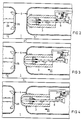
- Figures 1 to 12 relate to the first embodiment and each show a longitudinal section through the circuit breaker, with Figures 1 and 2 corresponding, but Figure 1 has a larger scale than the other figures.
- Figure 13 shows the second somewhat modified embodiment as a longitudinal section through the circuit breaker also on a larger scale corresponding to Figure 1.
- the same reference numbers are used in all figures for the same parts.
- the isolating switch 1 of a metal-encapsulated, with compressed gas, in particular SF6, insulated high-voltage switchgear lies in a tubular, metallic, grounded encapsulation 2.
- movable main switching pin 3 and the likewise tubular are surrounded by shielding field electrodes 5, the distance to the encapsulation 2 is not shown to scale.
- the isolating section 6 Between the end faces of the two field electrodes 5 there is the isolating section 6 indicated by arrows. It is bridged by the movable main switching pin 3 in the switched-on position of the isolating switch 1.
- the drive of the main switching pin 3 is not shown for better clarity. However, as is usual with disconnectors, it causes a relatively slow movement of the main switching pin 3. Therefore, in the interior of the tubular movable main switching pin 3, a centrally arranged auxiliary switching pin 7 is additionally provided, which remains in the interior of the main switching pin 3 in the rest position during the switch-on movement and during the switch-off movement is driven by a special spring 8 at a greater speed than that of the main switching pin 3.
- the spring 8 surrounds the auxiliary switching pin 7 and is designed as a compression spring. So that it can be clamped in a simple manner, the auxiliary switching pin 7, with its front end 9 facing the isolating section 6, passes through a clamping ring 10 located in the interior of the main switching pin 3, on which it is in the rest position, with the aid of a front stop 11, in which it is inside the main switch pin, comes to the system.
- a clamping ring 10 located in the interior of the main switching pin 3, on which it is in the rest position, with the aid of a front stop 11, in which it is inside the main switch pin, comes to the system.
- an adjusting screw 13 is provided, which widens conically.
- a mechanical control 14 for triggering the switch-off movement of the auxiliary switching pin 7 is arranged in the interior of the field electrode 5 surrounding the main switching pin 3.
- the lever arrangement of this mechanical control 14 consists of a two-armed angle lever 15, which is fixed in position in the fulcrum 16. This angle lever 15 is pressed in its rest position by the return spring 17 against the stationary stop 18. The ends of the two-armed angle lever 15 are deflected during the switching movement of the disconnector and are therefore provided with rollers, namely with the locking roller 19 which faces the auxiliary switching pin 7 and the switching roller 20 at the other end of the angle lever 15.
- the guide surface 21 for the switching roller 20 is connected via a bracket 22 to the main switching pin 3 and has two conically inclined, converging stop surfaces 23, 24, between which an area 25 extending parallel to the longitudinal axis of the main switching pin 3 extends.
- the inclination of the stop surface 24 is flatter than the radius of curvature of the lever arm of the angle lever 15 facing it.
- the switching roller 19, on the other hand, is deflected by the conical surface 26 of the set screw 13 and the end face 27 of the set screw 13 causes the self-locking jamming or blocking of the angle lever 15 against the attack 18.
- the counter contact for the auxiliary switching pin 7, which is designed as a shield electrode 28, is spring-loaded with a compression spring 29.
- the compression spring 29 When the compression spring 29 is in the rest position, the shield electrode 28 lies in the front opening 30 of the field electrode 5 of the mating contact 4.
- the surface of the shield electrode 28 is chosen so large that not only the end face 31 of the auxiliary switching pin 7 but also the end face 32 of the main switching pin 3 comes into contact with it.
- the disconnector 1 designed according to the invention functions as follows:
- FIG. 2 shows, like FIG. 1, the switch-off position of the disconnector in which the auxiliary switching pin 7 is located inside the movable main switching pin 3.
- the two-armed angle lever 15 of the mechanical control 14 is also in the rest position and is therefore pressed by the return spring 17 against the stop 18.
- the locking roller 19 and the switching roller 20 have no contact with other surfaces.
- FIG. 3 shows the start of the switch-on movement of the movable main switching pin 3, indicated by the arrow 33. This has already moved so far into the separating section 6 that the stop surface 24 of the guide surface 21 facing the main switching pin 3 has come into contact with the switching roller 20 of the angle lever 15 .
- the guide surface 21 deflects the angle lever 15 via the switching roller 20 until the switching roller 20 is initially in the region 25 of the guide surface 21 (FIG. 4) and then loses contact with the guide surface 21 after rolling on the stop surface 23, so that the angle lever 15 is pressed again by the return spring 17 against the stop 18 and thus assumes its rest position (Figure 5).
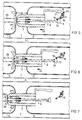
- the main switching pin 3 takes the auxiliary switching pin 7 with it when it is switched on.
- the locking roller 19 comes to rest on the conical surface 26 of the adjusting screw 13 before the main switching pin 3 has bridged the entire separation distance 6.
- the blocking roller 19 runs when the switch-on movement continues up on the conical surface 26 and thus in turn deflects the two-armed angle lever 15 from its rest position (FIG. 6), so that the adjusting screw 13 can pass the angle lever 15 without resistance.
- the main switching pin 3 comes to rest against the shield electrode 28, which forms the counter-contact for the auxiliary switching pin 7, and pushes it out of its rest position, the compression spring 29 being tensioned.
- the main switching pin 3 continues to switch on together with the auxiliary switching pin 7 until it has reached the switch-on position shown in FIG. 7, in which the main switching pin 3 is in contact with the mating contact 4 and with its end face 32 the shield electrode 28 in its end position inside the field electrode 5 is pressed in and the compression spring 29 has been tensioned.
- the end face 31 of the auxiliary switching pin 7 also abuts the shield electrode 28.
- the isolating switch 1 is therefore closed and the current is transmitted from the main switching pin 3 to the counter contact 4 and there is a potential connection between the auxiliary switching pin 7 and its counter contact formed by the shield electrode 28.
- the angle lever 15 of the mechanical control 14 is also in the rest position in the switched-on position.
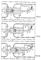
- Figure 8 shows the beginning of the switch-off movement of the main switching pin 3, indicated by the arrow 34.
- the compression spring 29 first relaxes, so that the shielding electrode 28 follows the main switching pin 3 somewhat and remains against its end face 32, whereby the end face 31 of the Auxiliary switching pin 7 presses in front of it.
- the end face 27 of the adjusting screw 13 comes into contact with the blocking roller 19 of the mechanical control 14 before the shield electrode 28 has reached the rest position, the latter automatically jams because the angle lever 15 is pressed against the stop 18.
- both the shield electrode 28 and the auxiliary switching pin 7 continue to move in the switch-off direction hindered.
- the main switching pin 3 has therefore already separated from the mating contact 4, while the potential connection between the auxiliary switching pin 7 and the shield electrode 28 is still maintained.
- the auxiliary switching pin 7 By relaxing the spring 8, the auxiliary switching pin 7 is drawn into the interior of the main switching pin 3 at high speed, which continues to move in the direction of switching off.
- the compression spring 29 is selected in its spring force so that it exerts an acceleration on the shield electrode 28 which is greater than the acceleration exerted by the spring 8 on the auxiliary switching pin 7, the auxiliary switching pin 7 initially remains in potential connection with the shielding electrodes 28 until it has reached its rest position.
- the auxiliary switching pin 7 accelerates already, so that at the moment of separation from the shield electrode 28 it already has a high speed, which is then increased still further. This improves the ability of the circuit breaker 1 to extinguish an arc, as occurs when switching magnetizing currents from transformers.
- the auxiliary switching pin 7 After the auxiliary switching pin 7 has reached its end position in the main switching pin 3, the two then move back together to the off position (FIGS. 1, 2).
- a small magnetizing current can be conducted via the spring 8 of the auxiliary switching pin 7 and the compression spring 29 of the shield electrode 28.
- it is necessary to insulate the spring 8 on one side which can be achieved by a bushing 36 made of insulating material arranged between the clamping ring 10 and the spring 8. Otherwise, this bushing 36 can be dispensed with.
- the sum of the lever arms of the two-armed angle lever 15 corresponds approximately to the distance 35 which the main switching pin 3 has when it is switched off from the counterelectrode 5 when the auxiliary switching pin is triggered.
- the end face 27 of the adjusting screw 13 must be located exactly below the intersection between the stop face 23 and the parallel region 25 of the guide face 21. If, on the other hand, the adjusting screw 13 is set such that in the switch-off position there is a distance 37, indicated by arrows in FIG. 1, between the end face 27 and the intersection 23/25, then this distance 37, which is positive (if it is in the switch-off direction) or negative (in the switch-on direction) can be taken into account accordingly.
- the adjusting screw 13 not only affects the bias of the spring 8th
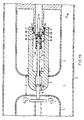
- FIG. 13 is a second embodiment of the circuit breaker 1 according to the invention, in which the mechanical control 14 has a somewhat modified shape.
- FIG. 13 shows the main switching pin 3 at the start of the switch-off movement 34 at a point in time at which the auxiliary switching pin 7 is still resting on the shield electrode 28 with its end face 31. This is not yet in its rest position, but is held in place by the auxiliary switching pin 7 when the compression spring 29 is under tension, because the auxiliary switching pin 7 prevents it from being switched off by the blocking via the mechanical control 14.
- the mechanical control 14 consists of two two-armed levers 38 arranged symmetrically to the longitudinal axis of the main switching pin 3, each of which carries a switching roller 20 and a locking roller 19 at the ends and is fixed in position in the pivot point 16.
- the return spring 17 tries to pull the two ends of the lever 38 carrying the locking roller 19 together. These rest in the rest position against a stop formed by a central extension 39 of the auxiliary switching pin 7.
- the auxiliary control pin is thus additionally centered by the mechanical control 14.
- the guide surfaces 21 for deflecting the switching rollers 20 are arranged directly on the main switching pin 3 in this isolating switch 1. They are conically inclined to the inner bore 40 of the main switching pin 3 and dimensioned so that at the desired time according to the position of the main switching pin 3 in the separating section 6 during the switch-off movement, the locking rollers 19 lift off the stop and the auxiliary switching pin 7 is released.
- a protective tube 41 is provided which surrounds the spring 8 of the auxiliary switching pin 7. In this way it is prevented that the locking rollers 19 come into contact with the gears of the spring 8.
- the length of the protective tube 41 is chosen so that the spring 8 is protected in every position of the auxiliary switching pin 7.
Landscapes
- Driving Mechanisms And Operating Circuits Of Arc-Extinguishing High-Tension Switches (AREA)
- Gas-Insulated Switchgears (AREA)
Claims (9)
- Sectionneur pour installations de coupure à haute tension à blindage métallique et à isolation par un gaz sous pression, comportant une section de séparation (6) située entre des électrodes de champ (5) et qui peut être shuntée par un manchon tubulaire mobile de coupure principale (3), dont le contact antagoniste fixe (4) est réalisé avec une forme creuse, et dans lequel le manchon mobile de coupure principale (3) comporte une broche de coupure auxiliaire (7) mobile axialement dans ce manchon et qui traverse, par son extrémité (9) tournée vers la section de séparation (6), une bague de serrage (10) à l'intérieur du manchon de coupure principale (3) et est entourée par un ressort (8), qui s'étend entre la bague de serrage (10) et une butée (13) située sur la broche de coupure auxiliaire (7), et selon lequel, lorsque le sectionneur (1) est dans la position ouverte, la broche de coupure auxiliaire (7) est située à l'intérieur du manchon mobile de coupure auxiliaire (3) et, lorsque le sectionneur (1) est dans la position fermée, la broche de coupure auxiliaire (7) vient s'appliquer contre un contact antagoniste (28) chargé par un ressort et situé dans le contact antagoniste creux (4) du manchon de coupure principale (3), et subsiste ainsi, au début du déplacement d'ouverture du manchon mobile de coupure principale (3) sous l'action du ressort (8), après une libération par une unité de commande mécanique (14) montée fixe à l'intérieur de l'une des électrodes de champ (5), la broche soit ramenée dans la position de repos avec une vitesse supérieure à la vitesse de déplacement du manchon mobile de coupure principale (3), caractérisé par le fait que l'unité de commande mécanique (14) comporte un dispositif à leviers monté pivotant qui se bloque automatiquement dans la position fermée et est disposé dans l'électrode de champ (5) associée au manchon de coupure principale (3) et qui ne gêne pas le mouvement de fermeture de la broche de coupure auxiliaire (7) et la maintient fermement au début du mouvement d'ouverture du manchon de coupure principale (3) jusqu'à ce que la broche soit déviée par une surface de guidage (21) reliée au manchon principale (3).
- Sectionneur suivant la revendication 1, caractérisé par le fait que le contact antagoniste de la broche de coupure auxiliaire (7) possède une électrode de blindage (28), qui est chargée par un ressort et, dans sa position de repos, est située dans une ouverture (30) de l'électrode de champ (5) et contre laquelle vient s'appliquer également le manchon de coupure principale (30), le manchon de coupure principale repoussant la broche à l'intérieur de l'électrode de champ (5), lorsque le sectionneur est dans la position fermée, que le ressort (29), qui agit sur l'électrode blindage (28) produit une accélération qui, jusqu'à ce que soit atteinte la position de repos de l'électrode de blindage (28) lors du mouvement d'ouverture, est supérieure à l'accélération de la broche de coupure auxiliaire (7).
- Sectionneur suivant la revendication 1 ou 2, caractérisé par le fait que le dispositif à leviers comporte des leviers (15) à deux bras.
- Sectionneur suivant la revendication 1 ou 2 ou 3, caractérisé par le fait que dans le dispositif à leviers, le bras de levier des leviers (15) correspond approximativement à la distance entre la surface frontale (32) du manchon de coupure principale (3) et l'électrode de champ (5) du contact antagoniste (4) pour une déviation maximale du dispositif à leviers (15) par la surface de guidage (21).
- Sectionneur suivant une ou plusieurs des revendications 1 à 4, caractérisé par le fait qu'un ressort de rappel (17) repousse le dispositif à leviers (15) dans la position de repos contre une butée (18).
- Sectionneur suivant la revendication 5, caractérisé par le fait que le dispositif à leviers comporte deux leviers (38) disposés symétriquement par rapport à l'axe longitudinal du manchon de coupure principale (3) et qui sont reliés par le ressort de rappel (17) et sont repoussés contre une butée médiane (32) de la broche de coupure auxiliaire (7).
- Sectionneur suivant l'une des revendications 1 à 6, caractérisé par le fait que la surface de guidage (21) est réalisée sous la forme d'une came qui possède une partie qui s'étend parallèlement à l'axe longitudinal du manchon mobile de coupure principale (3).
- Sectionneur suivant une ou plusieurs des revendications 1 à 7, caractérisé par le fait que les extrémités des leviers du dispositif à leviers, qui s'appliquent contre une butée (13, 39) ou contre une surface de guidage (21), sont pourvues chacune d'un galet (19, 20).
- Sectionneur suivant une ou plusieurs des revendications 1 à 8, caractérisé par le fait que la butée située à l'extrémité de la broche de coupure auxiliaire est formée par la surface frontale (27) d'une vis de réglage (13), qui s'élargit avec une forme conique, pour le ressort (8) qui entoure la broche de coupure auxiliaire (7).
Applications Claiming Priority (3)
| Application Number | Priority Date | Filing Date | Title |
|---|---|---|---|
| DE3938711A DE3938711A1 (de) | 1989-11-17 | 1989-11-17 | Trennschalter fuer metallgekapselte, druckgasisolierte hochspannungsschaltanlagen |
| DE3938711 | 1989-11-17 | ||
| PCT/DE1990/000722 WO1991007768A1 (fr) | 1989-11-17 | 1990-09-19 | Sectionneur pour appareillages haute tension sous blindage metallique avec isolation par gaz comprime |
Publications (2)
| Publication Number | Publication Date |
|---|---|
| EP0500550A1 EP0500550A1 (fr) | 1992-09-02 |
| EP0500550B1 true EP0500550B1 (fr) | 1994-06-15 |
Family
ID=6393982
Family Applications (1)
| Application Number | Title | Priority Date | Filing Date |
|---|---|---|---|
| EP90914126A Expired - Lifetime EP0500550B1 (fr) | 1989-11-17 | 1990-09-19 | Sectionneur pour appareillages haute tension sous blindage metallique avec isolation par gaz comprime |
Country Status (6)
| Country | Link |
|---|---|
| US (1) | US5237137A (fr) |
| EP (1) | EP0500550B1 (fr) |
| AT (1) | ATE107434T1 (fr) |
| CA (1) | CA2068866A1 (fr) |
| DE (2) | DE3938711A1 (fr) |
| WO (1) | WO1991007768A1 (fr) |
Families Citing this family (14)
| Publication number | Priority date | Publication date | Assignee | Title |
|---|---|---|---|---|
| DE9108589U1 (de) * | 1991-07-09 | 1991-09-05 | Siemens AG, 8000 München | Trennschalter mit einem Hauptschaltstift und einem Hilfskontaktstift |
| DE4204529A1 (de) * | 1992-02-15 | 1993-08-19 | Asea Brown Boveri | Trennschalter fuer eine metallgekapselte gasisolierte hochspannungsanlage |
| DE4211156A1 (de) * | 1992-03-31 | 1993-10-07 | Siemens Ag | Elektrischer Hochspannungs-Leistungsschalter |
| DE19533794A1 (de) * | 1995-09-13 | 1997-03-20 | Abb Patent Gmbh | Metallgekapselter, gasisolierter Hochspannungsschalter |
| WO2012003527A1 (fr) | 2010-07-07 | 2012-01-12 | Kaon Holdings Pty Ltd | Isolateur électrique |
| KR101771465B1 (ko) * | 2011-07-25 | 2017-09-06 | 엘에스산전 주식회사 | 가스절연 개폐장치 |
| FR2984590B1 (fr) * | 2011-12-14 | 2014-07-04 | Alstom Technology Ltd | Ensemble conducteur mobile pour sectionneur, comprenant un ressort permettant d'accelerer la separation des contacts d'arc |
| EP2728602B1 (fr) * | 2012-11-05 | 2015-01-21 | ABB Technology AG | Séparateur de charge haute tension électrique et procédé d'ouverture de celui-ci |
| US20140174895A1 (en) * | 2012-12-20 | 2014-06-26 | Abb Technology Ag | Contact arrangement for high voltage switchgear with contact arrangement |
| DE102013205945A1 (de) * | 2013-04-04 | 2014-10-09 | Siemens Aktiengesellschaft | Trennschalteinrichtung |
| JP6067182B1 (ja) * | 2015-11-16 | 2017-01-25 | 三菱電機株式会社 | 開閉器 |
| EP3226276B1 (fr) * | 2016-03-31 | 2021-03-10 | Siemens Energy Global GmbH & Co. KG | Sectionneur adapté aux moyennes et hautes tensions et méthode de déconnexion au moyen dudit sectionneur |
| WO2018036904A1 (fr) * | 2016-08-26 | 2018-03-01 | Abb Schweiz Ag | Interrupteur et procédé de séparation des contacts d'un interrupteur |
| WO2019064446A1 (fr) * | 2017-09-28 | 2019-04-04 | 三菱電機株式会社 | Dispositif de commutation |
Family Cites Families (4)
| Publication number | Priority date | Publication date | Assignee | Title |
|---|---|---|---|---|
| DE3122442A1 (de) * | 1981-06-02 | 1982-12-23 | Siemens AG, 1000 Berlin und 8000 München | Trennschalter fuer hochspannungsanlagen |
| FR2547107B1 (fr) * | 1983-06-06 | 1986-05-09 | Merlin Gerin | Sectionneur d'isolement blinde |
| DE8323522U1 (de) * | 1983-08-15 | 1987-11-05 | Siemens AG, 1000 Berlin und 8000 München | Trennschalter für metallgekapselte, druckgasisolierte Hochspannungsschaltanlagen |
| DE3832171A1 (de) * | 1988-07-01 | 1990-01-04 | Licentia Gmbh | Einrichtung zur raschen ein- und ausschaltung von kleinen stroemen fuer trennschalter von v.i.s. |
-
1989
- 1989-11-17 DE DE3938711A patent/DE3938711A1/de not_active Withdrawn
-
1990
- 1990-09-19 WO PCT/DE1990/000722 patent/WO1991007768A1/fr active IP Right Grant
- 1990-09-19 EP EP90914126A patent/EP0500550B1/fr not_active Expired - Lifetime
- 1990-09-19 CA CA002068866A patent/CA2068866A1/fr not_active Abandoned
- 1990-09-19 AT AT90914126T patent/ATE107434T1/de not_active IP Right Cessation
- 1990-09-19 US US07/857,936 patent/US5237137A/en not_active Expired - Fee Related
- 1990-09-19 DE DE59006161T patent/DE59006161D1/de not_active Expired - Fee Related
Also Published As
| Publication number | Publication date |
|---|---|
| EP0500550A1 (fr) | 1992-09-02 |
| DE59006161D1 (de) | 1994-07-21 |
| ATE107434T1 (de) | 1994-07-15 |
| CA2068866A1 (fr) | 1991-05-18 |
| WO1991007768A1 (fr) | 1991-05-30 |
| US5237137A (en) | 1993-08-17 |
| DE3938711A1 (de) | 1991-05-23 |
Similar Documents
| Publication | Publication Date | Title |
|---|---|---|
| DE69205069T2 (de) | Mittelspannungslastschalter mit reduzierter Steuerenergie. | |
| EP0809269B1 (fr) | Disjoncteur haute tension avec deux pièces de contact entraínées | |
| EP0500550B1 (fr) | Sectionneur pour appareillages haute tension sous blindage metallique avec isolation par gaz comprime | |
| DE2460628C3 (de) | Elektrisches Schaltgerät | |
| EP0070794A2 (fr) | Disjoncteur avec interrupteur à vide | |
| DE19631323C1 (de) | Druckgasschalter | |
| EP0763840B1 (fr) | Disjoncteur à haute tension dans un boítier métallique isolé par gaz | |
| DE3242014A1 (de) | Gasisolierter stromkreis-trenner bzw. -ausschalter | |
| DE69213082T2 (de) | Gasisolierter Trennschalter und Schaltvorrichtung | |
| DE3319010C2 (fr) | ||
| CH660645A5 (de) | Elektrischer trennschalter. | |
| EP0138743B1 (fr) | Sectionneur pour appareillage de commutation haute tension, logé dans une enceinte métallique à gaz comprimé | |
| DE3122442A1 (de) | Trennschalter fuer hochspannungsanlagen | |
| WO1991015025A1 (fr) | Disjoncteur pour coupure en charge a gaz comprime avec piston de compression commande | |
| DE3930548C2 (de) | Druckgasschalter | |
| EP0809268A2 (fr) | Disjoncteur haute tension dÔté d'une tuyère en matière isolante | |
| DE4234065C1 (de) | Schaltgerät | |
| EP1837889A2 (fr) | Ensemble interrupteur avec une résistance de démarrage | |
| EP0104599A2 (fr) | Sectionneur haute tension avec contacts préliminaires | |
| DE8119801U1 (de) | Kontaktsystem für Druckgas-Leistungsschalter | |
| DE3237146A1 (de) | Metallgekapseltes hochspannungsschaltgeraet | |
| DE2759265A1 (de) | Druckgasschalter | |
| DE19730583A1 (de) | Druckgasschalter | |
| DE2703550C2 (de) | Elektrischer Schalter | |
| DE1640236C3 (de) | Hochspannungs- Schalteinrichtung |
Legal Events
| Date | Code | Title | Description |
|---|---|---|---|
| PUAI | Public reference made under article 153(3) epc to a published international application that has entered the european phase |
Free format text: ORIGINAL CODE: 0009012 |
|
| 17P | Request for examination filed |
Effective date: 19920408 |
|
| AK | Designated contracting states |
Kind code of ref document: A1 Designated state(s): AT BE CH DE DK ES FR GB IT LI LU NL SE |
|
| 17Q | First examination report despatched |
Effective date: 19930913 |
|
| GRAA | (expected) grant |
Free format text: ORIGINAL CODE: 0009210 |
|
| AK | Designated contracting states |
Kind code of ref document: B1 Designated state(s): AT BE CH DE DK ES FR GB IT LI LU NL SE |
|
| PG25 | Lapsed in a contracting state [announced via postgrant information from national office to epo] |
Ref country code: NL Effective date: 19940615 Ref country code: ES Free format text: THE PATENT HAS BEEN ANNULLED BY A DECISION OF A NATIONAL AUTHORITY Effective date: 19940615 Ref country code: DK Effective date: 19940615 Ref country code: BE Effective date: 19940615 |
|
| REF | Corresponds to: |
Ref document number: 107434 Country of ref document: AT Date of ref document: 19940715 Kind code of ref document: T |
|
| REF | Corresponds to: |
Ref document number: 59006161 Country of ref document: DE Date of ref document: 19940721 |
|
| ITF | It: translation for a ep patent filed | ||
| PG25 | Lapsed in a contracting state [announced via postgrant information from national office to epo] |
Ref country code: SE Effective date: 19940915 |
|
| PG25 | Lapsed in a contracting state [announced via postgrant information from national office to epo] |
Ref country code: AT Effective date: 19940919 |
|
| PG25 | Lapsed in a contracting state [announced via postgrant information from national office to epo] |
Ref country code: LU Free format text: LAPSE BECAUSE OF NON-PAYMENT OF DUE FEES Effective date: 19940930 |
|
| GBT | Gb: translation of ep patent filed (gb section 77(6)(a)/1977) |
Effective date: 19940902 |
|
| ET | Fr: translation filed | ||
| NLV1 | Nl: lapsed or annulled due to failure to fulfill the requirements of art. 29p and 29m of the patents act | ||
| PLBE | No opposition filed within time limit |
Free format text: ORIGINAL CODE: 0009261 |
|
| STAA | Information on the status of an ep patent application or granted ep patent |
Free format text: STATUS: NO OPPOSITION FILED WITHIN TIME LIMIT |
|
| 26N | No opposition filed | ||
| PGFP | Annual fee paid to national office [announced via postgrant information from national office to epo] |
Ref country code: GB Payment date: 19960821 Year of fee payment: 7 |
|
| PGFP | Annual fee paid to national office [announced via postgrant information from national office to epo] |
Ref country code: FR Payment date: 19960926 Year of fee payment: 7 |
|
| PGFP | Annual fee paid to national office [announced via postgrant information from national office to epo] |
Ref country code: DE Payment date: 19961118 Year of fee payment: 7 |
|
| PGFP | Annual fee paid to national office [announced via postgrant information from national office to epo] |
Ref country code: CH Payment date: 19961216 Year of fee payment: 7 |
|
| PG25 | Lapsed in a contracting state [announced via postgrant information from national office to epo] |
Ref country code: GB Free format text: LAPSE BECAUSE OF NON-PAYMENT OF DUE FEES Effective date: 19970919 |
|
| PG25 | Lapsed in a contracting state [announced via postgrant information from national office to epo] |
Ref country code: LI Free format text: LAPSE BECAUSE OF NON-PAYMENT OF DUE FEES Effective date: 19970930 Ref country code: FR Free format text: THE PATENT HAS BEEN ANNULLED BY A DECISION OF A NATIONAL AUTHORITY Effective date: 19970930 Ref country code: CH Free format text: LAPSE BECAUSE OF NON-PAYMENT OF DUE FEES Effective date: 19970930 |
|
| GBPC | Gb: european patent ceased through non-payment of renewal fee |
Effective date: 19970919 |
|
| REG | Reference to a national code |
Ref country code: CH Ref legal event code: PL |
|
| PG25 | Lapsed in a contracting state [announced via postgrant information from national office to epo] |
Ref country code: DE Free format text: LAPSE BECAUSE OF NON-PAYMENT OF DUE FEES Effective date: 19980603 |
|
| REG | Reference to a national code |
Ref country code: FR Ref legal event code: ST |
|
| PG25 | Lapsed in a contracting state [announced via postgrant information from national office to epo] |
Ref country code: IT Free format text: LAPSE BECAUSE OF NON-PAYMENT OF DUE FEES;WARNING: LAPSES OF ITALIAN PATENTS WITH EFFECTIVE DATE BEFORE 2007 MAY HAVE OCCURRED AT ANY TIME BEFORE 2007. THE CORRECT EFFECTIVE DATE MAY BE DIFFERENT FROM THE ONE RECORDED. Effective date: 20050919 |