EP0499954A1 - Method and assembly for wrapping rolls, paper rolls in particular, in a wrapper sheet - Google Patents
Method and assembly for wrapping rolls, paper rolls in particular, in a wrapper sheet Download PDFInfo
- Publication number
- EP0499954A1 EP0499954A1 EP92102305A EP92102305A EP0499954A1 EP 0499954 A1 EP0499954 A1 EP 0499954A1 EP 92102305 A EP92102305 A EP 92102305A EP 92102305 A EP92102305 A EP 92102305A EP 0499954 A1 EP0499954 A1 EP 0499954A1
- Authority
- EP
- European Patent Office
- Prior art keywords
- wrapper
- roll
- melting
- assembly
- zones
- Prior art date
- Legal status (The legal status is an assumption and is not a legal conclusion. Google has not performed a legal analysis and makes no representation as to the accuracy of the status listed.)
- Granted
Links
Images

Classifications
-
- B—PERFORMING OPERATIONS; TRANSPORTING
- B65—CONVEYING; PACKING; STORING; HANDLING THIN OR FILAMENTARY MATERIAL
- B65B—MACHINES, APPARATUS OR DEVICES FOR, OR METHODS OF, PACKAGING ARTICLES OR MATERIALS; UNPACKING
- B65B11/00—Wrapping, e.g. partially or wholly enclosing, articles or quantities of material, in strips, sheets or blanks, of flexible material
- B65B11/04—Wrapping, e.g. partially or wholly enclosing, articles or quantities of material, in strips, sheets or blanks, of flexible material the articles being rotated
-
- B—PERFORMING OPERATIONS; TRANSPORTING
- B65—CONVEYING; PACKING; STORING; HANDLING THIN OR FILAMENTARY MATERIAL
- B65B—MACHINES, APPARATUS OR DEVICES FOR, OR METHODS OF, PACKAGING ARTICLES OR MATERIALS; UNPACKING
- B65B25/00—Packaging other articles presenting special problems
- B65B25/14—Packaging paper or like sheets, envelopes, or newspapers, in flat, folded, or rolled form
- B65B25/146—Packaging paper or like sheets, envelopes, or newspapers, in flat, folded, or rolled form packaging rolled-up articles
- B65B25/148—Jumbo paper rolls
Definitions
- the present invention relates to a method in accordance with the preamble of claim 1 for wrapping rolls, paper rolls in particular, in a wrapper sheet.
- the roll is wrapped in a wrapper material, whose surface is coated with a heat-meltable laminate layer, by rotating the paper roll on support rolls or an equivalent rotating apparatus and guiding the wrapper sheet about the roll so that the side coated with the laminate layer faces the roll.
- the wrapper is attached onto the roll by converting the laminate layer to a partially or fully fluid or semi-solid state, whereby it acts as a glue.
- the invention also concerns an assembly in accordance with claim 3 for wrapping a roll, a paper roll in particular, in a wrapper by rotating the roll.
- paper rolls are packaged in wrappers sealed with end headers.
- the wrapper sheet conventionally employed is comprised of several layers, frequently in a combination of kraft wrapper-plastic film laminate-kraft wrapper (e.g. Kraftliner 100 g/m2 + PE 40 g/m2 + Kraftliner 100 g/m2).
- the purpose of the packaging system is to protect the roll against humidity, physical blows and to provide the possibility of mechanical handling without damaging the roll itself. Further, two or more small rolls are often packed in a single package, whereby the packaging system must be sufficiently strong to keep the package together.
- Acceptable outcome of packaging is related to several factors. Efficient initial gluing is necessary for achieving a tight wrap and a smooth wrapper surface without wrinkles to keep the wrapper straight and tensioned during roll wrapping. For rolls that must be free from the initial adhesive stripe as defined by customer specification, wrap tension is attained by the use of a guide-about apparatus. The quality of such wrapping remains inferior, however.
- Successful folding of the wrapper sheet requires correct application of pressure by the crimping arms and proper moisture content (8...11 %) of the wrap. At a correct level of moisture content, the fold becomes sharp and the folded edge remains parallel with the roll end. The moisture content of the wrapper often drops further during storage, whereby the wrapper becomes tight and small wrinkles are smoothed away.
- the wrapper sheet is often sealed using a hot-melt or cold-setting glue.
- Gluing takes place by spraying glue stripes onto the wrap, whereby the wrapper is adhered to the roll over the width (3...5 mm) of the glue stripes.
- implementations based on hot-melt gluing that use a wrapping material having a layer of heat-meltable laminate on the wrap.
- the US patent publication 4,716,709 for example describes the method outlined in the introductory part of this text, in which method the start end and the finish end of the wrapper sheet are sealed to the roll by melting the polyethene film coat of the wrapping material.
- the plastic film laminate acts both as a moisture barrier and a glue layer. Melting in accordance with the US patent takes place with the help of a heater bar which is pressed against the paper layer of the wrap.
- a problem in the above described methods is posed by the small area of glue adherence that lowers the durability and moisture barrier characteristics of the wrap.
- the highest wear of the wrapper is concentrated to the angle of the wrapper at the corner of the roll end and roll circumference, where a small air pocket (earmark) unavoidably remains. This occurs during the folding of the wrapper at points where the wrapper sheet remains detached from the roll during the wrap-about and consequently does not fold sufficiently sharply parallel to the roll end.
- both hot-melt and cold glue applicator apparatuses require frequent servicing due to their complicated structure. Therefore, wrapping costs become a dominating factor in the total costs of roll packaging.
- the method according to the invention in which the wrapper sheet is hot-melt glued in accordance with the US patent 4,716,709 on the roll, is based on the concept of adhering the wrapper on the roll being wrapped also during roll wrapping.
- at least a portion of the plastic film laminate surface between the start end and the finish end of the wrapper sheet is melted in order to attach the plastic film laminate to the roll being wrapped also for this portion.
- the application area of melting energy is altered appropriately in the direction of the center axis of the roll during wrapping to attain a desired glue adherence pattern.
- the wrapping material has a multilayer composition in which the plastic film laminate is comprised of a polymer material possibly complemented with additives.
- Typical heat-meltable bonding polymers are, for example, polyolefins such as polypropene and particularly polyethene.
- the plastic film laminate or one or more of its layers also act as a moisture barrier.
- melting in the context of this patent application is used to mean the conversion of the coat into a partially or entirely fluid or semi-solid state in which it acts as a glue, that is, with an adhering property that makes it stick to the paper roll, wrapping material or similar surface to be glued.
- the melting process is advantageously carried out in accordance with the invention prior to the entrance of the wrapper into the pressing nip.
- the invention also permits the use of suitable waxes and similar materials as the heat-meltable coat material.
- the wrapping material is melted from the laminate side, that is, the melting energy is applied or transferred to the wrapping material from the laminate side.
- This is an advantageous approach, because if the introduction of the melting energy into the laminate to be activated should be attempted from the kraft sheet side, energy would effectively be absorbed in the kraft sheet, which would appreciably complicate the arrangement of effective energy introduction.
- the present invention aims at large adhering areas and sufficiently rapid throughput times of paper roll wrapping. Practical experiences from energy introduction via the kraft sheet side have proven this approach incapable of satisfying the criteria of throughput goals.
- the melting of the laminate layer can be implemented in a number of alternative ways.
- An advantageous method is by way of radiation heating using, e.g., infra-red radiation, but such methods as hot-air jets, flame manifolds, ultrasound transducers, lasers, microwave sources, heated steel bars, heated steel rolls and similar means can be used as well.
- the melting process is controllable by zones in a desired manner, whereby such a zonal control permits the formation of desired adhesive patterns and handling of different widths of wrapping materials (using typical zone widths of 10...500 mm).
- the means for wrapper sealing in the assembly according to the present invention comprise a melting unit divided into at least two melting zones which can be controlled partially or entirely independently from each other and which can be directed against the surface of the wrapper in order to produce the thermal effect necessary for at least a partial melting of the plastic film laminate.
- the melting zones are advantageously arranged adjacent in the direction of and aligned parallel to the center axis of the roll, and their number is at least 2, preferably approx. 5...50. A higher number of the melting zones permits greater definition in the formation of the melting pattern.
- the melting zones of the melting unit use infra-red emitters as the melting elements.
- Power control means of the melting zones permit the thermal effect imposed by the heating zones on the wrapping material to be adjusted in the direction of the center axis of the paper roll in order to achieve a desired melting pattern.
- Zonal control is based on the adjustment of the melting energy application area and/or output level and/or combination of these. Therefore, the control can be implemented by way of several different control elements and methods. Such possibilities are offered, for example, by power control of the zones, distance control of the zones and/or the wrapping material backing, partial or total gating of energy emitted from the zones as well as the deflection of energy emitted from the zones.
- the zones can also be physically shifted with respect to the paper roll being wrapped with the help of appropriate shifting means.
- the shifting can take place longitudinally along or transversely to the wrapper web, or alternatively, obliquely to the web.
- the zonal control is not, however, limited to the above described methods, but rather, all other prior-art and advancing zonal control methods are feasible within the scope of the present invention.
- Zonal control can be performed as a continuous process during roll wrapping and/or presetting the energy transferring assembly prior to the wrapping process.
- the desired adhesive pattern can be formed to consist of points, stripes, or alternatively, of a homogeneously sealed area.
- the method according to the present invention is advantageously carried out using the last one of these alternatives.
- the wrapper in which at least two turns of wrapper are wrapped about the paper roll, the wrapper is then sealed during the first turn of the wrapper only by its center part.
- the adhesive pattern is widened in steps or continuously until it reaches the edge of the wrapper.
- the wrapper is sealed during the second wrapping turn at least for a part of the turn over its entire width.
- the roll is further wrapped by a third turn that is advantageously sealed over its entire width.
- This wrapping scheme prevents the wrapper from adhering to the roll end, whereby it could damage the roll end in the case the inner header does not fully cover the roll head.
- the invention provides significant benefits, and a specific value of the scheme is gained from its capability of attaining the required temperature extremely rapidly and of offering an easy alignment of the heating effect emitted by the zonally controlled melting unit.
- Figure 1 shows a roll packaging line in a perspective view
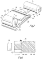
- Figure 2 shows correspondingly a wrapping station in a perspective view
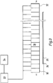
- Figure 3 shows diagrammatically the design of a melting unit employed in the invention
- Figure 4 shows the form of a preferred adhesive pattern.
- the rolls are transferred on a conveyor 1 toward the packaging line. Each roll awaits at the end of the conveyor until a pusher 2 is enabled to transfer the roll to a centering station 3 where the roll is identified, centered, weighed and measured for its dimensions. In addition, the system computes the necessary packaging parameters from the data measured by the centering station.
- the roll is transferred onto a stepping conveyor 4. Along this conveyor the rolls are transferred in steps first to a wrapping station 5 and further to an end header pressing station 6.
- the inner header placing arms 7 first press the inner header against the roll head. Header holding arms 15 are lowered and a header holder platen is pushed outward.
- the inner headers are sorted by their diameter on header dispensing shelves 8.
- the machine operator typically loads the header dispensing shelves 8 and wrapper dispensing stations 9 latest when the packaging line is halted.
- the program selects an optimal wrapper 12 for each roll from one of the wrapper dispensing stations 9.
- the crimping units move toward the roll until the header holder platens can keep the inner header in place.
- Crimping vanes 10 start to rotate and a crimping arm 11 is lowered onto the roll.
- the wrapper 12 is fed from a wrapper roll 24 via the nip between two pressing rolls 19 along a feed table 20 and under the roll 23 to be wrapped.
- the wrapper 12 employed in the exemplifying embodiment is comprised of two layers forming a composition of kraft wrapper 25 with plastic film laminate 26 (e.g. Kraftliner 250 g/m2 + polyethene 40 g/m2).
- the reference number 22 denotes a guide of the wrapper web.
- a melting unit 21 above the wrapper web 12 heats the plastic film laminate of the wrapper web 12 so as to adhere the wrapper to the roll 23.
- the travel of the wrapper web 12 is braked with the help of web tension control elements 14 in order to obtain a tightly wrapped package.
- the rotating crimping vanes 10 fold the wrapper edges overhanging the roll ends down parallel with the roll end.
- the packages contain typically two or three turns of wrapper.
- the melting assembly 21 employed in the invention is in the exemplifying embodiment arranged in front of support rolls 13 on which the roll is rotated.
- the method according to the invention is implemented most appropriately by forming the desired adhesive pattern with the help of the zonal control of the melting unit.
- the wrapper is sealed during the first roll wrapping turn only at the center of the wrapper, while the second wrapper turn, and when necessary also the third wrapper turn, is sealed over the entire wrapper width as illustrated in Fig. 4 (the hatched area designates melted wrapper laminate).
- the melting pattern is widened during the second turn up to the edges of the wrapper.
- the above described wrapping scheme prevents the wrapper from adhering to the roll end and thereby damaging the roll end in the case the inner header for some reason fails to fully cover the roll head.
- Fig. 3 illustrates the construction of a melting unit suitable for zonal control.
- the melting unit 31 is divided in the wrapper cross direction into blocks or zones V1 ... V n the number of which is n.
- Each zone V n of the melting unit contains a melting element 32, each of which is directly connected to input power supply and control units 33 and 34. These units make it possible to control the power level (0...100 %) applied onto the wrapper via each melting unit, thus affecting the melting profile produced by the entire melting unit.
- the melting energy is applied onto the activatable layer or layers 26 of the wrapping material 12 that in this manner are converted to the molten state, thus attaining the adhesive property.
- the paper rolls to be wrapped typically have a diameter of 500...1800 mm and width of 500...3000 mm.
- a crucial design factor is how rapidly the power output profile can be widened toward the edges when the smallest possible roll (minimum size roll) is followed by the largest possible roll (maximum size roll).
- Wrapping speed on the wrapping lines is 0.6 ... 1.5 m/s.
- the cycle time varies in the range of 20...60 s, most commonly in the range of 25...35 s.
- the power output is preferably designed for melting a wrapper web travelling at 1.5 m/s speed.
- the melting assembly is employed to apply a heating power of approx. 25...50 W per cm square onto the wrapper web.
- the wrapper consumption is 17 m wrapper web on a maximum size roll (using three wrapper turns). Time used for wrapping in this case is approx. 11 s plus the transfer and positioning times of the crimping elements.
- the set wrapping speed can be slightly reduced, because the above described gluing method facilitates an appreciably enlarged adherence area and thus a stiffer packaging. Consequently, also the number of wrapper turns can be reduced thus keeping the cycle time unchanged.
- the underside portion of the melting unit can be replaced by a separate reflector, which by the same token improves the focusing of the thermal energy onto the plastic film laminate of the wrapping material.
- the reflector can typically be constructed from a suitable sheet metal or ceramic material.
- the wrapper web 12 is severed either by stopping the travel of the web 12 and cutting the web, or alternatively, by hitting the web over the entire machine width with a blade, whereby the web is severed while travelling at full speed.
- the crimping arms 11 and header holding arms 15 are raised to their home positions after completion of wrapping, and the roll travels on the stepper conveyor 16 to the attachment of the outer headers.
- the pressing station performs the attachment of the outer headers to the ends of the paper roll.
- the headers are placed on the pressing platens 17 either manually or with the help of a manipulator. After this, the pressing platens 17 rotate onto the support rolls and reach against the roll ends simultaneously heating the PE laminate layer on the inside of the headers.
- the headers are sealed to the roll when their PE laminate layer is heated to approx. 200 °C with the help of the pressing platens.
- the entire pressing takes about 5...10 s.
- the packaging line also includes an apparatus for sticking labels to the roll surface.
- the labelling apparatus is placed according to system layout either at the wrapping station 5, the pressing station 6 or any station following the pressing station.
- Some packaging schemes also require a stripe marking apparatus, which is used for painting one or more colour stripes to the side of the package.
- the purpose of the stripes is to indicate, for example, that two rolls are wrapped in a single package.
- the present invention can have alternative embodiments different from the exemplifying embodiment described above.
- the zonal control can be implemented using other control means than input power control.
- the wrapper web can be laminated with some other kind of polyolefin or any other suitable plastic material or even wax.
Abstract
Description
- The present invention relates to a method in accordance with the preamble of
claim 1 for wrapping rolls, paper rolls in particular, in a wrapper sheet. - According to the present method, the roll is wrapped in a wrapper material, whose surface is coated with a heat-meltable laminate layer, by rotating the paper roll on support rolls or an equivalent rotating apparatus and guiding the wrapper sheet about the roll so that the side coated with the laminate layer faces the roll. The wrapper is attached onto the roll by converting the laminate layer to a partially or fully fluid or semi-solid state, whereby it acts as a glue.
- The invention also concerns an assembly in accordance with claim 3 for wrapping a roll, a paper roll in particular, in a wrapper by rotating the roll.
- In the paper industry, paper rolls are packaged in wrappers sealed with end headers. The wrapper sheet conventionally employed is comprised of several layers, frequently in a combination of kraft wrapper-plastic film laminate-kraft wrapper (e.g. Kraftliner 100 g/m² + PE 40 g/m² + Kraftliner 100 g/m²). The purpose of the packaging system is to protect the roll against humidity, physical blows and to provide the possibility of mechanical handling without damaging the roll itself. Further, two or more small rolls are often packed in a single package, whereby the packaging system must be sufficiently strong to keep the package together.
- Acceptable outcome of packaging is related to several factors. Efficient initial gluing is necessary for achieving a tight wrap and a smooth wrapper surface without wrinkles to keep the wrapper straight and tensioned during roll wrapping. For rolls that must be free from the initial adhesive stripe as defined by customer specification, wrap tension is attained by the use of a guide-about apparatus. The quality of such wrapping remains inferior, however. Successful folding of the wrapper sheet requires correct application of pressure by the crimping arms and proper moisture content (8...11 %) of the wrap. At a correct level of moisture content, the fold becomes sharp and the folded edge remains parallel with the roll end. The moisture content of the wrapper often drops further during storage, whereby the wrapper becomes tight and small wrinkles are smoothed away.
- In present methods, the wrapper sheet is often sealed using a hot-melt or cold-setting glue. Gluing takes place by spraying glue stripes onto the wrap, whereby the wrapper is adhered to the roll over the width (3...5 mm) of the glue stripes. Also known in the art are implementations based on hot-melt gluing that use a wrapping material having a layer of heat-meltable laminate on the wrap. The US patent publication 4,716,709 for example describes the method outlined in the introductory part of this text, in which method the start end and the finish end of the wrapper sheet are sealed to the roll by melting the polyethene film coat of the wrapping material. The plastic film laminate acts both as a moisture barrier and a glue layer. Melting in accordance with the US patent takes place with the help of a heater bar which is pressed against the paper layer of the wrap.
- A problem in the above described methods is posed by the small area of glue adherence that lowers the durability and moisture barrier characteristics of the wrap. When paper rolls are stacked above one another, the highest wear of the wrapper is concentrated to the angle of the wrapper at the corner of the roll end and roll circumference, where a small air pocket (earmark) unavoidably remains. This occurs during the folding of the wrapper at points where the wrapper sheet remains detached from the roll during the wrap-about and consequently does not fold sufficiently sharply parallel to the roll end. Furthermore, both hot-melt and cold glue applicator apparatuses require frequent servicing due to their complicated structure. Therefore, wrapping costs become a dominating factor in the total costs of roll packaging.
- It is an object of the present invention to overcome disadvantages hampering the prior-art designs and to achieve a novel method and a novel assembly for wrapping rolls, paper rolls in particular, in a wrap.
- The method according to the invention, in which the wrapper sheet is hot-melt glued in accordance with the US patent 4,716,709 on the roll, is based on the concept of adhering the wrapper on the roll being wrapped also during roll wrapping. Thus, at least a portion of the plastic film laminate surface between the start end and the finish end of the wrapper sheet is melted in order to attach the plastic film laminate to the roll being wrapped also for this portion. When necessary, the application area of melting energy is altered appropriately in the direction of the center axis of the roll during wrapping to attain a desired glue adherence pattern.
- More specifically, the method according to the invention is characterized by what is stated in the characterizing part of
claim 1. - Furthermore, the assembly according to the invention is characterized by what is stated in the characterizing part of claim 3.
- According to the invention, the wrapping material has a multilayer composition in which the plastic film laminate is comprised of a polymer material possibly complemented with additives. Typical heat-meltable bonding polymers are, for example, polyolefins such as polypropene and particularly polyethene. Besides its primary adhesive properties, the plastic film laminate or one or more of its layers also act as a moisture barrier.
- The term melting in the context of this patent application is used to mean the conversion of the coat into a partially or entirely fluid or semi-solid state in which it acts as a glue, that is, with an adhering property that makes it stick to the paper roll, wrapping material or similar surface to be glued. The melting process is advantageously carried out in accordance with the invention prior to the entrance of the wrapper into the pressing nip.
- The invention also permits the use of suitable waxes and similar materials as the heat-meltable coat material.
- The wrapping material is melted from the laminate side, that is, the melting energy is applied or transferred to the wrapping material from the laminate side. This is an advantageous approach, because if the introduction of the melting energy into the laminate to be activated should be attempted from the kraft sheet side, energy would effectively be absorbed in the kraft sheet, which would appreciably complicate the arrangement of effective energy introduction. The present invention aims at large adhering areas and sufficiently rapid throughput times of paper roll wrapping. Practical experiences from energy introduction via the kraft sheet side have proven this approach incapable of satisfying the criteria of throughput goals.
- The melting of the laminate layer can be implemented in a number of alternative ways. An advantageous method is by way of radiation heating using, e.g., infra-red radiation, but such methods as hot-air jets, flame manifolds, ultrasound transducers, lasers, microwave sources, heated steel bars, heated steel rolls and similar means can be used as well.
- An essential requirement according to the invention is that the melting process is controllable by zones in a desired manner, whereby such a zonal control permits the formation of desired adhesive patterns and handling of different widths of wrapping materials (using typical zone widths of 10...500 mm). For this purpose, the means for wrapper sealing in the assembly according to the present invention comprise a melting unit divided into at least two melting zones which can be controlled partially or entirely independently from each other and which can be directed against the surface of the wrapper in order to produce the thermal effect necessary for at least a partial melting of the plastic film laminate. The melting zones are advantageously arranged adjacent in the direction of and aligned parallel to the center axis of the roll, and their number is at least 2, preferably approx. 5...50. A higher number of the melting zones permits greater definition in the formation of the melting pattern.
- According to a preferred embodiment of the invention, the melting zones of the melting unit use infra-red emitters as the melting elements.
- Power control means of the melting zones permit the thermal effect imposed by the heating zones on the wrapping material to be adjusted in the direction of the center axis of the paper roll in order to achieve a desired melting pattern. Zonal control is based on the adjustment of the melting energy application area and/or output level and/or combination of these. Therefore, the control can be implemented by way of several different control elements and methods. Such possibilities are offered, for example, by power control of the zones, distance control of the zones and/or the wrapping material backing, partial or total gating of energy emitted from the zones as well as the deflection of energy emitted from the zones. The zones can also be physically shifted with respect to the paper roll being wrapped with the help of appropriate shifting means. The shifting can take place longitudinally along or transversely to the wrapper web, or alternatively, obliquely to the web. The zonal control is not, however, limited to the above described methods, but rather, all other prior-art and advancing zonal control methods are feasible within the scope of the present invention.
- Zonal control can be performed as a continuous process during roll wrapping and/or presetting the energy transferring assembly prior to the wrapping process.
- The desired adhesive pattern can be formed to consist of points, stripes, or alternatively, of a homogeneously sealed area. The method according to the present invention is advantageously carried out using the last one of these alternatives. In a preferred embodiment of the invention, in which at least two turns of wrapper are wrapped about the paper roll, the wrapper is then sealed during the first turn of the wrapper only by its center part. During the second wrapping turn the adhesive pattern is widened in steps or continuously until it reaches the edge of the wrapper. Thus, the wrapper is sealed during the second wrapping turn at least for a part of the turn over its entire width. When necessary, the roll is further wrapped by a third turn that is advantageously sealed over its entire width. This wrapping scheme prevents the wrapper from adhering to the roll end, whereby it could damage the roll end in the case the inner header does not fully cover the roll head.
- The invention provides significant benefits, and a specific value of the scheme is gained from its capability of attaining the required temperature extremely rapidly and of offering an easy alignment of the heating effect emitted by the zonally controlled melting unit.
- The invention is next examined in greater detail with the help of the attached drawings, in which
Figure 1 shows a roll packaging line in a perspective view, while Figure 2 shows correspondingly a wrapping station in a perspective view. Figure 3 shows diagrammatically the design of a melting unit employed in the invention and Figure 4 shows the form of a preferred adhesive pattern. - The rolls are transferred on a
conveyor 1 toward the packaging line. Each roll awaits at the end of the conveyor until apusher 2 is enabled to transfer the roll to a centering station 3 where the roll is identified, centered, weighed and measured for its dimensions. In addition, the system computes the necessary packaging parameters from the data measured by the centering station. - From the centering station 3 the roll is transferred onto a stepping
conveyor 4. Along this conveyor the rolls are transferred in steps first to a wrappingstation 5 and further to an endheader pressing station 6. On the wrappingstation 5 the inner header placing arms 7 first press the inner header against the roll head.Header holding arms 15 are lowered and a header holder platen is pushed outward. The inner headers are sorted by their diameter onheader dispensing shelves 8. The machine operator typically loads theheader dispensing shelves 8 and wrapper dispensing stations 9 latest when the packaging line is halted. On the basis of data received from the centering station 3, the program selects anoptimal wrapper 12 for each roll from one of the wrapper dispensing stations 9. - From the wrapping
station 5 the crimping units move toward the roll until the header holder platens can keep the inner header in place. Crimpingvanes 10 start to rotate and a crimpingarm 11 is lowered onto the roll. As is illustrated in Fig. 2, thewrapper 12 is fed from awrapper roll 24 via the nip between twopressing rolls 19 along a feed table 20 and under theroll 23 to be wrapped. Thewrapper 12 employed in the exemplifying embodiment is comprised of two layers forming a composition ofkraft wrapper 25 with plastic film laminate 26 (e.g. Kraftliner 250 g/m² + polyethene 40 g/m²). Thereference number 22 denotes a guide of the wrapper web. Amelting unit 21 above thewrapper web 12 heats the plastic film laminate of thewrapper web 12 so as to adhere the wrapper to theroll 23. During roll wrapping the travel of thewrapper web 12 is braked with the help of webtension control elements 14 in order to obtain a tightly wrapped package. When thewrapper web 12 has reached the top of theroll 23, the rotating crimpingvanes 10 fold the wrapper edges overhanging the roll ends down parallel with the roll end. The packages contain typically two or three turns of wrapper. - The
melting assembly 21 employed in the invention is in the exemplifying embodiment arranged in front of support rolls 13 on which the roll is rotated. - As noted above, the method according to the invention is implemented most appropriately by forming the desired adhesive pattern with the help of the zonal control of the melting unit. For example, the wrapper is sealed during the first roll wrapping turn only at the center of the wrapper, while the second wrapper turn, and when necessary also the third wrapper turn, is sealed over the entire wrapper width as illustrated in Fig. 4 (the hatched area designates melted wrapper laminate). The melting pattern is widened during the second turn up to the edges of the wrapper.
- The above described wrapping scheme prevents the wrapper from adhering to the roll end and thereby damaging the roll end in the case the inner header for some reason fails to fully cover the roll head.
- Fig. 3 illustrates the construction of a melting unit suitable for zonal control. The
melting unit 31 is divided in the wrapper cross direction into blocks or zones V₁ ... Vn the number of which is n. Each zone Vn of the melting unit contains amelting element 32, each of which is directly connected to input power supply andcontrol units - The melting energy is applied onto the activatable layer or layers 26 of the wrapping
material 12 that in this manner are converted to the molten state, thus attaining the adhesive property. - The paper rolls to be wrapped typically have a diameter of 500...1800 mm and width of 500...3000 mm. In the planning of the power output profile capabilities of the melting unit a crucial design factor is how rapidly the power output profile can be widened toward the edges when the smallest possible roll (minimum size roll) is followed by the largest possible roll (maximum size roll).
- Wrapping speed on the wrapping lines is 0.6 ... 1.5 m/s. The cycle time varies in the range of 20...60 s, most commonly in the range of 25...35 s. The power output is preferably designed for melting a wrapper web travelling at 1.5 m/s speed. The melting assembly is employed to apply a heating power of approx. 25...50 W per cm square onto the wrapper web. Then, the wrapper consumption is 17 m wrapper web on a maximum size roll (using three wrapper turns). Time used for wrapping in this case is approx. 11 s plus the transfer and positioning times of the crimping elements.
- When necessary the set wrapping speed can be slightly reduced, because the above described gluing method facilitates an appreciably enlarged adherence area and thus a stiffer packaging. Consequently, also the number of wrapper turns can be reduced thus keeping the cycle time unchanged.
- The underside portion of the melting unit can be replaced by a separate reflector, which by the same token improves the focusing of the thermal energy onto the plastic film laminate of the wrapping material. When a
melting unit 31 comprised of infra-red radiators is employed, the reflector can typically be constructed from a suitable sheet metal or ceramic material. - The
wrapper web 12 is severed either by stopping the travel of theweb 12 and cutting the web, or alternatively, by hitting the web over the entire machine width with a blade, whereby the web is severed while travelling at full speed. The crimpingarms 11 andheader holding arms 15 are raised to their home positions after completion of wrapping, and the roll travels on thestepper conveyor 16 to the attachment of the outer headers. - The pressing station performs the attachment of the outer headers to the ends of the paper roll. The headers are placed on the
pressing platens 17 either manually or with the help of a manipulator. After this, thepressing platens 17 rotate onto the support rolls and reach against the roll ends simultaneously heating the PE laminate layer on the inside of the headers. The headers are sealed to the roll when their PE laminate layer is heated to approx. 200 °C with the help of the pressing platens. The entire pressing takes about 5...10 s. - The packaging line also includes an apparatus for sticking labels to the roll surface. The labelling apparatus is placed according to system layout either at the wrapping
station 5, thepressing station 6 or any station following the pressing station. - Some packaging schemes also require a stripe marking apparatus, which is used for painting one or more colour stripes to the side of the package. The purpose of the stripes is to indicate, for example, that two rolls are wrapped in a single package.
- In addition to those described above, the present invention can have alternative embodiments different from the exemplifying embodiment described above. For example, as already mentioned, the zonal control can be implemented using other control means than input power control. Instead of polyethene, the wrapper web can be laminated with some other kind of polyolefin or any other suitable plastic material or even wax.
Claims (12)
- A method for wrapping rolls, paper rolls in particular, in a wrapper (12) of a material whose surface is coated with a laminate comprised of a heat-meltable layer (26), in which method- a paper roll (23) is rotated on support rolls (13) or similar rotating means,- the wrapper (12) is guided about the roll (23) so that the laminate layer (26) comes against the roll,- the wrapper (12) is adhered onto the roll by applying energy onto the plastic film laminate to attain at least a partial melting of said layer, whereby the wrapper (12) adheres to the roll (23), and- the roll (23) being rotated is wrapped into at least one turn of the wrapper (12),characterized in that- at least a part of the wrapper laminate layer (26) is melted from the laminate side to adhere the wrapper at least partially to the roll being wrapped, and- when necessary, the area and/or energy density of melting energy applied onto the wrapper material is varied in the direction of the center axis of the roll in order to achieve a desired pattern of adherence.
- A method as defined in claim 1, characterized in that such a wrapper material is used in which the laminate layer comprises at least one layer of heat-activatable (heat-meltable) material such as a wax or plastic film, in particular polyethene film.
- An assembly for wrapping a roll, a paper roll in particular, in a wrapper by rotating the roll, said assembly comprising- at least one wrapper material roll (24) containing wrapper material (12) whose surface is coated with a laminate layer (26) of heat-meltable material,- support rolls (13) or similar means for rotating a paper roll (23),- means (20) for guiding the wrapper material (12) from the wrapper material roll (24) about the roll (23) to be wrapped,- means for severing the wrapper material (12), and- means (21) for adhering the wrapper material (12),characterized in that- the means for adhering said wrapper material (12) comprise a melting unit (31), which is divided in at least two melting zones, and said melting zones (Vn) can be controlled partially or entirely independently from each other and can be directed against the surface of the wrapper material (12) in order to produce the thermal effect necessary for at least a partial melting of said laminate layer (26).
- An assembly as defined in claim 3, characterized in that the melting zones (Vn) are arranged adjacent in the direction of the center axis of the roll (23).
- An assembly as defined in claim 3 or 4, characterized in that the number of the melting zones (Vn) is at least 2, preferably approx. 5...50.
- An assembly as defined in any foregoing claim 3...5, characterized in that power control means (33, 34) of the melting zones (Vn) permit the thermal effect imposed by the heating zones on the wrapping material to be adjusted in the direction of the center axis of the paper roll in order to achieve a desired melting pattern.
- An assembly as defined in claim 6, characterized in that the power control means of the melting zones (Vn) are comprised of input power controllers (33, 34).
- An assembly as defined in claim 6, characterized in that control means of the melting zones are comprised of control means of mutual distance between said melting zones and said wrapper material.
- An assembly as defined in claim 6, characterized in that control means of the melting zones are comprised of control means of mutual distance between said melting zones and said roll to be wrapped.
- An assembly as defined in claim 6, characterized in that control means of the melting zones are comprised of shading and/or deflecting elements arranged between said melting zones and said wrapper material.
- An assembly as defined in any foregoing claim 3...10, characterized in that said melting zones (Vn) are arranged to heat said wrapper material (12) from the side of the laminate layer (26).
- An assembly as defined in any foregoing claim 3...11, characterized in that said melting zones (Vn) are comprised of infra-red emitters, liquefied-gas burning flame manifolds, hot-air jets, lasers, ultrasound transducers, microwave sources, heated steel bars or heated steel rolls.
Applications Claiming Priority (2)
| Application Number | Priority Date | Filing Date | Title |
|---|---|---|---|
| FI910665 | 1991-02-12 | ||
| FI910665A FI89149C (en) | 1991-02-12 | 1991-02-12 | Foerfarande och anordning Foer emballering av rullar, i synnerhet pappersrullar, med foerpackningsomslag |
Publications (2)
| Publication Number | Publication Date |
|---|---|
| EP0499954A1 true EP0499954A1 (en) | 1992-08-26 |
| EP0499954B1 EP0499954B1 (en) | 1996-05-01 |
Family
ID=8531897
Family Applications (1)
| Application Number | Title | Priority Date | Filing Date |
|---|---|---|---|
| EP92102305A Expired - Lifetime EP0499954B1 (en) | 1991-02-12 | 1992-02-12 | Method and assembly for wrapping rolls, paper rolls in particular, in a wrapper sheet |
Country Status (7)
| Country | Link |
|---|---|
| US (1) | US5265399A (en) |
| EP (1) | EP0499954B1 (en) |
| AT (1) | ATE137460T1 (en) |
| CA (1) | CA2061102C (en) |
| DE (1) | DE69210279T2 (en) |
| ES (1) | ES2091343T3 (en) |
| FI (1) | FI89149C (en) |
Cited By (18)
| Publication number | Priority date | Publication date | Assignee | Title |
|---|---|---|---|---|
| DE4314480C1 (en) * | 1993-05-03 | 1995-01-05 | Kleinewefers Gmbh | Process and apparatus for the packaging of a material-web roll |
| DE4340515A1 (en) * | 1993-11-29 | 1995-06-01 | Kleinewefers Gmbh | Method and device for packaging a roll of material web |
| FR2715371A1 (en) * | 1994-01-21 | 1995-07-28 | Sppr | Method of automatically wrapping foie gras under aluminium@ foil |
| WO1996026112A1 (en) * | 1995-02-21 | 1996-08-29 | Fas Converting Machinery Ab | Device and method in wrapping machine |
| EP0759396A1 (en) | 1995-08-17 | 1997-02-26 | Voith Sulzer Finishing GmbH | Device and method for packaging a roll of web material |
| WO1997008053A1 (en) * | 1995-08-29 | 1997-03-06 | Fas Converting Machinery Ab | Process and apparatus for synthetic packaging |
| DE19535746A1 (en) * | 1995-09-26 | 1997-04-03 | Voith Sulzer Finishing Gmbh | Method and device for packaging a roll of material web |
| EP1090842A1 (en) | 1999-10-08 | 2001-04-11 | Voith Sulzer Papiertechnik Patent GmbH | Device for packaging rolls |
| EP1277658A1 (en) * | 2001-07-18 | 2003-01-22 | Voith Paper Patent GmbH | Apparatus and method for packaging a roll of web material |
| EP1293433A1 (en) * | 2001-09-17 | 2003-03-19 | Pesmel OY | Method for holding a label or a protector to a side surface of a piece to be wrapped |
| EP1323634A1 (en) * | 2001-12-25 | 2003-07-02 | Fuji Photo Film Co., Ltd. | Method of and system for automatically packaging photosensitive film rolls |
| DE19961667B4 (en) * | 1999-12-21 | 2004-04-22 | Voith Paper Patent Gmbh | Packing device for attaching a front cover |
| WO2005092710A1 (en) * | 2004-03-26 | 2005-10-06 | Saimatec Engineering Oy | Head press |
| WO2006067272A1 (en) * | 2004-12-23 | 2006-06-29 | Metso Paper, Inc. | Method and arrangement for placing reel end shields |
| WO2007042625A1 (en) * | 2005-10-14 | 2007-04-19 | Metso Paper, Inc. | Method and apparatus for transporting rolls during packing |
| EP2157019A2 (en) * | 2008-08-05 | 2010-02-24 | Voith Patent GmbH | Packing assembly for packaging material sheet rolls and method for improving packaging quality |
| US7703259B2 (en) | 2004-04-14 | 2010-04-27 | Metso Paper Inc. | Apparatus for transporting rolls during packing |
| CN112265662A (en) * | 2020-10-22 | 2021-01-26 | 江阴快力特机械有限公司 | Plastic floor coiled material packaging assembly line |
Families Citing this family (11)
| Publication number | Priority date | Publication date | Assignee | Title |
|---|---|---|---|---|
| DE69514329T2 (en) * | 1995-05-24 | 2000-08-10 | Agfa Gevaert Nv | Process for light-tight packaging of a stack of photosensitive sheets |
| DE19535189C1 (en) * | 1995-09-22 | 1996-12-19 | Voith Sulzer Finishing Gmbh | Packaging of wound paper rolls |
| DE19652451C2 (en) * | 1996-12-17 | 2000-04-13 | Voith Sulzer Finishing Gmbh | Method and device for packaging a roll of material web |
| FI110600B (en) * | 1998-01-16 | 2003-02-28 | Metso Paper Inc | Method and apparatus for wrapping paper and cardboard rolls in a packaging wrap |
| FI103958B (en) * | 1998-04-01 | 1999-10-29 | Valmet Corp | Method and Arrangement for Inserting the End of a Conveyor Trail into a Draw Roll Nip in a Roll Wrapper |
| FI116719B (en) * | 2004-04-14 | 2006-02-15 | Metso Paper Inc | Procedure for centering rolls |
| FI20041252A (en) | 2004-09-28 | 2006-03-29 | Metso Paper Inc | Method and apparatus for packing rollers |
| US20060260755A1 (en) * | 2005-05-23 | 2006-11-23 | Crum Jesse D | System for producing pressure sensitive intermediate web assembly having regularly occurring discontinuous segments produced in a continuous fashion |
| US7404485B2 (en) * | 2006-05-24 | 2008-07-29 | David Uitenbroek | Paper roll wrap, wrapped paper roll, and method for wrapping a paper roll |
| SE535693C2 (en) * | 2006-12-07 | 2012-11-13 | Mondecon Ab | Procedure for packaging paper and cardboard rolls |
| US20140014711A1 (en) * | 2012-07-13 | 2014-01-16 | Atlantic Coated Papers Ltd. | Protective wrapper for rolls and method for wrapping a roll using the same |
Citations (5)
| Publication number | Priority date | Publication date | Assignee | Title |
|---|---|---|---|---|
| GB1052568A (en) * | 1900-01-01 | |||
| US3875723A (en) * | 1973-05-21 | 1975-04-08 | Conwed Corp | Wrapping apparatus for cylindrical shapes |
| WO1983001765A1 (en) * | 1981-11-16 | 1983-05-26 | Schneck, Hans | Method and apparatus for packaging paper rolls |
| US4716709A (en) * | 1986-10-06 | 1988-01-05 | Howard City Paper Company | Apparatus and method for roll wrapping with poly-coated paper |
| US4945707A (en) * | 1989-04-24 | 1990-08-07 | K. C. Technical Servies, Inc. | Machine and method for overwrapping cylindrical articles |
Family Cites Families (8)
| Publication number | Priority date | Publication date | Assignee | Title |
|---|---|---|---|---|
| US1573669A (en) * | 1924-02-19 | 1926-02-16 | Charles W H Bolingbroke | Package-sealing device |
| US2638725A (en) * | 1950-05-12 | 1953-05-19 | Stadler Hurter & Company | Paper roll wrapping machine |
| US3342014A (en) * | 1964-09-29 | 1967-09-19 | Beloit Eastern Corp | Roll wrapper |
| US3374598A (en) * | 1964-11-17 | 1968-03-26 | Corning Glass Works | Seal and the method and apparatus for making same |
| US3411269A (en) * | 1965-07-15 | 1968-11-19 | Beloit Eastern Corp | Crimper paddle |
| SE441819B (en) * | 1984-04-03 | 1985-11-11 | Stretch Emballering Ab | Packing process and packing material for carrying out the process |
| US4864802A (en) * | 1984-08-31 | 1989-09-12 | The Crowell Corporation | Packaging |
| US4693056A (en) * | 1985-10-04 | 1987-09-15 | The Crowell Corporation | Heat sealing and packaging |
-
1991
- 1991-02-12 FI FI910665A patent/FI89149C/en active
-
1992
- 1992-02-06 US US07/831,881 patent/US5265399A/en not_active Expired - Lifetime
- 1992-02-12 CA CA002061102A patent/CA2061102C/en not_active Expired - Lifetime
- 1992-02-12 ES ES92102305T patent/ES2091343T3/en not_active Expired - Lifetime
- 1992-02-12 AT AT92102305T patent/ATE137460T1/en not_active IP Right Cessation
- 1992-02-12 EP EP92102305A patent/EP0499954B1/en not_active Expired - Lifetime
- 1992-02-12 DE DE69210279T patent/DE69210279T2/en not_active Expired - Lifetime
Patent Citations (5)
| Publication number | Priority date | Publication date | Assignee | Title |
|---|---|---|---|---|
| GB1052568A (en) * | 1900-01-01 | |||
| US3875723A (en) * | 1973-05-21 | 1975-04-08 | Conwed Corp | Wrapping apparatus for cylindrical shapes |
| WO1983001765A1 (en) * | 1981-11-16 | 1983-05-26 | Schneck, Hans | Method and apparatus for packaging paper rolls |
| US4716709A (en) * | 1986-10-06 | 1988-01-05 | Howard City Paper Company | Apparatus and method for roll wrapping with poly-coated paper |
| US4945707A (en) * | 1989-04-24 | 1990-08-07 | K. C. Technical Servies, Inc. | Machine and method for overwrapping cylindrical articles |
Cited By (30)
| Publication number | Priority date | Publication date | Assignee | Title |
|---|---|---|---|---|
| US5477659A (en) * | 1993-05-03 | 1995-12-26 | Sulzer Papertec Krefeld Gmbh | Method and arrangement for the packaging of a material-web roll |
| DE4314480C1 (en) * | 1993-05-03 | 1995-01-05 | Kleinewefers Gmbh | Process and apparatus for the packaging of a material-web roll |
| DE4340515A1 (en) * | 1993-11-29 | 1995-06-01 | Kleinewefers Gmbh | Method and device for packaging a roll of material web |
| US5548942A (en) * | 1993-11-29 | 1996-08-27 | Sulzer Papertec Krefeld Gmbh | Method and apparatus for packaging a roll of material |
| FR2715371A1 (en) * | 1994-01-21 | 1995-07-28 | Sppr | Method of automatically wrapping foie gras under aluminium@ foil |
| US5927047A (en) * | 1995-02-21 | 1999-07-27 | Fas Converting Machinery Ab | Device and method in wrapping machine |
| WO1996026112A1 (en) * | 1995-02-21 | 1996-08-29 | Fas Converting Machinery Ab | Device and method in wrapping machine |
| EP0759396A1 (en) | 1995-08-17 | 1997-02-26 | Voith Sulzer Finishing GmbH | Device and method for packaging a roll of web material |
| US6029423A (en) * | 1995-08-29 | 2000-02-29 | Fas Converting Machinery Ab | Process and apparatus for synthetic packaging |
| WO1997008053A1 (en) * | 1995-08-29 | 1997-03-06 | Fas Converting Machinery Ab | Process and apparatus for synthetic packaging |
| DE19535746C2 (en) * | 1995-09-26 | 1998-05-28 | Voith Sulzer Finishing Gmbh | Method and device for packaging a roll of material web |
| US5768858A (en) * | 1995-09-26 | 1998-06-23 | Voith Sulzer Finishing Gmbh | Method and apparatus for packaging a roll of material |
| DE19535746A1 (en) * | 1995-09-26 | 1997-04-03 | Voith Sulzer Finishing Gmbh | Method and device for packaging a roll of material web |
| DE19549664C2 (en) * | 1995-09-26 | 2003-06-26 | Voith Paper Patent Gmbh | Device for packaging a roll of material web |
| EP1090842A1 (en) | 1999-10-08 | 2001-04-11 | Voith Sulzer Papiertechnik Patent GmbH | Device for packaging rolls |
| DE19961667B4 (en) * | 1999-12-21 | 2004-04-22 | Voith Paper Patent Gmbh | Packing device for attaching a front cover |
| EP1277658A1 (en) * | 2001-07-18 | 2003-01-22 | Voith Paper Patent GmbH | Apparatus and method for packaging a roll of web material |
| EP1293433A1 (en) * | 2001-09-17 | 2003-03-19 | Pesmel OY | Method for holding a label or a protector to a side surface of a piece to be wrapped |
| EP1323634A1 (en) * | 2001-12-25 | 2003-07-02 | Fuji Photo Film Co., Ltd. | Method of and system for automatically packaging photosensitive film rolls |
| US7032361B2 (en) | 2001-12-25 | 2006-04-25 | Fuji Photo Film Co., Ltd. | Method of and system for automatically packaging rolls |
| WO2005092710A1 (en) * | 2004-03-26 | 2005-10-06 | Saimatec Engineering Oy | Head press |
| US7703259B2 (en) | 2004-04-14 | 2010-04-27 | Metso Paper Inc. | Apparatus for transporting rolls during packing |
| US7559182B2 (en) | 2004-12-23 | 2009-07-14 | Metso Paper, Inc. | Method and arrangement for placing reel end shields |
| WO2006067272A1 (en) * | 2004-12-23 | 2006-06-29 | Metso Paper, Inc. | Method and arrangement for placing reel end shields |
| WO2007042625A1 (en) * | 2005-10-14 | 2007-04-19 | Metso Paper, Inc. | Method and apparatus for transporting rolls during packing |
| US7661243B2 (en) | 2005-10-14 | 2010-02-16 | Metso Paper, Inc. | Apparatus for transporting rolls during packing |
| CN101326103B (en) * | 2005-10-14 | 2012-05-16 | 美特索造纸公司 | Method and apparatus for transporting rolls during packing |
| EP2157019A2 (en) * | 2008-08-05 | 2010-02-24 | Voith Patent GmbH | Packing assembly for packaging material sheet rolls and method for improving packaging quality |
| EP2157019A3 (en) * | 2008-08-05 | 2012-08-22 | Voith Patent GmbH | Packing assembly for packaging material sheet rolls and method for improving packaging quality |
| CN112265662A (en) * | 2020-10-22 | 2021-01-26 | 江阴快力特机械有限公司 | Plastic floor coiled material packaging assembly line |
Also Published As
| Publication number | Publication date |
|---|---|
| FI910665A0 (en) | 1991-02-12 |
| ES2091343T3 (en) | 1996-11-01 |
| DE69210279T2 (en) | 1996-12-05 |
| DE69210279D1 (en) | 1996-06-05 |
| FI89149B (en) | 1993-05-14 |
| CA2061102A1 (en) | 1992-08-13 |
| FI89149C (en) | 1996-09-11 |
| ATE137460T1 (en) | 1996-05-15 |
| FI910665A (en) | 1992-08-13 |
| US5265399A (en) | 1993-11-30 |
| EP0499954B1 (en) | 1996-05-01 |
| CA2061102C (en) | 2001-04-24 |
Similar Documents
| Publication | Publication Date | Title |
|---|---|---|
| EP0499954B1 (en) | Method and assembly for wrapping rolls, paper rolls in particular, in a wrapper sheet | |
| CA1128485A (en) | Helically wound core and method of producing same | |
| US4704173A (en) | System for applying heat shrink film to containers and other articles and heat shrinking the same | |
| KR100233230B1 (en) | Method and apparatus for manufacturing cigarette packs | |
| US4844957A (en) | System for applying heat shrink film to containers and other articles and heat shrinking the same | |
| US5732533A (en) | Process and apparatus for producing packs with an outer wrapper consisting of paper or the like | |
| US5240529A (en) | System for applying heat shrink film to containers and other articles and heat shrinking the same | |
| EP0437353B1 (en) | Method and apparatus for heat sealing labels on containers | |
| US20130112343A1 (en) | Method of conforming a label to the contour of a container | |
| CA2318409C (en) | Method and apparatus for wrapping of paper and board rolls into a package wrapping | |
| CZ300214B6 (en) | Method for the regulation of the temperature of the heated air when pasting plastic films and apparatus for making the same | |
| CA1068209A (en) | Wrapping process and apparatus | |
| FI108857B (en) | Device for handling film and wrapping device | |
| US5271783A (en) | Method and apparatus for heat sealing labels on containers | |
| EP1053180B1 (en) | A method for treating plastic film and a device in a wrapping machine | |
| US4284448A (en) | Method and an arrangement for the manufacture of casings | |
| CA2182044C (en) | Device and method for wrapping a roll of continuous web material | |
| CA1313122C (en) | Method and apparatus for wrapping a roll, particularly a paper roll | |
| JPH0329788A (en) | Method to fit thermoplastic small piece to container | |
| AU638004B2 (en) | Improvements in or relating to film packaging | |
| GB2119308A (en) | Sealing lids to tray-like containers | |
| CA2013402A1 (en) | Method for packaging books | |
| CA1196848A (en) | Method and apparatus for high speed pouch and bag making | |
| CA1149794A (en) | Method and apparatus for using a helically wound core | |
| JP3174161B2 (en) | Surface treatment equipment for can body blanks |
Legal Events
| Date | Code | Title | Description |
|---|---|---|---|
| PUAI | Public reference made under article 153(3) epc to a published international application that has entered the european phase |
Free format text: ORIGINAL CODE: 0009012 |
|
| AK | Designated contracting states |
Kind code of ref document: A1 Designated state(s): AT CH DE ES FR GB IT LI SE |
|
| 17P | Request for examination filed |
Effective date: 19930129 |
|
| 17Q | First examination report despatched |
Effective date: 19940715 |
|
| GRAH | Despatch of communication of intention to grant a patent |
Free format text: ORIGINAL CODE: EPIDOS IGRA |
|
| GRAA | (expected) grant |
Free format text: ORIGINAL CODE: 0009210 |
|
| AK | Designated contracting states |
Kind code of ref document: B1 Designated state(s): AT CH DE ES FR GB IT LI SE |
|
| REF | Corresponds to: |
Ref document number: 137460 Country of ref document: AT Date of ref document: 19960515 Kind code of ref document: T |
|
| REF | Corresponds to: |
Ref document number: 69210279 Country of ref document: DE Date of ref document: 19960605 |
|
| ITF | It: translation for a ep patent filed |
Owner name: ISTANZA DI FUSIONE IN CORSO DI ESAME;DR. ING. A. R |
|
| REG | Reference to a national code |
Ref country code: CH Ref legal event code: PUE Owner name: VALMET PAPER MACHINERY INC. TRANSFER- VALMET CORPO Ref country code: CH Ref legal event code: NV Representative=s name: A. BRAUN, BRAUN, HERITIER, ESCHMANN AG PATENTANWAE |
|
| RAP2 | Party data changed (patent owner data changed or rights of a patent transferred) |
Owner name: VALMET CORPORATION |
|
| ET | Fr: translation filed | ||
| REG | Reference to a national code |
Ref country code: GB Ref legal event code: 732E |
|
| REG | Reference to a national code |
Ref country code: ES Ref legal event code: FG2A Ref document number: 2091343 Country of ref document: ES Kind code of ref document: T3 |
|
| PLBE | No opposition filed within time limit |
Free format text: ORIGINAL CODE: 0009261 |
|
| STAA | Information on the status of an ep patent application or granted ep patent |
Free format text: STATUS: NO OPPOSITION FILED WITHIN TIME LIMIT |
|
| REG | Reference to a national code |
Ref country code: ES Ref legal event code: PC2A |
|
| 26N | No opposition filed | ||
| REG | Reference to a national code |
Ref country code: GB Ref legal event code: IF02 |
|
| REG | Reference to a national code |
Ref country code: CH Ref legal event code: PFA Owner name: VALMET CORPORATION Free format text: VALMET CORPORATION#PANUNTIE 6#00620 HELSINKI (FI) -TRANSFER TO- VALMET CORPORATION#PANUNTIE 6#00620 HELSINKI (FI) |
|
| PGFP | Annual fee paid to national office [announced via postgrant information from national office to epo] |
Ref country code: ES Payment date: 20090219 Year of fee payment: 18 |
|
| PGFP | Annual fee paid to national office [announced via postgrant information from national office to epo] |
Ref country code: FR Payment date: 20090213 Year of fee payment: 18 |
|
| PGFP | Annual fee paid to national office [announced via postgrant information from national office to epo] |
Ref country code: GB Payment date: 20100218 Year of fee payment: 19 Ref country code: AT Payment date: 20100212 Year of fee payment: 19 |
|
| REG | Reference to a national code |
Ref country code: FR Ref legal event code: ST Effective date: 20101029 |
|
| PG25 | Lapsed in a contracting state [announced via postgrant information from national office to epo] |
Ref country code: FR Free format text: LAPSE BECAUSE OF NON-PAYMENT OF DUE FEES Effective date: 20100301 |
|
| PGFP | Annual fee paid to national office [announced via postgrant information from national office to epo] |
Ref country code: IT Payment date: 20110221 Year of fee payment: 20 Ref country code: DE Payment date: 20110218 Year of fee payment: 20 Ref country code: SE Payment date: 20110214 Year of fee payment: 20 Ref country code: CH Payment date: 20110222 Year of fee payment: 20 |
|
| GBPC | Gb: european patent ceased through non-payment of renewal fee |
Effective date: 20110212 |
|
| REG | Reference to a national code |
Ref country code: ES Ref legal event code: FD2A Effective date: 20111118 |
|
| PG25 | Lapsed in a contracting state [announced via postgrant information from national office to epo] |
Ref country code: AT Free format text: LAPSE BECAUSE OF NON-PAYMENT OF DUE FEES Effective date: 20110212 |
|
| PG25 | Lapsed in a contracting state [announced via postgrant information from national office to epo] |
Ref country code: ES Free format text: LAPSE BECAUSE OF NON-PAYMENT OF DUE FEES Effective date: 20100213 |
|
| REG | Reference to a national code |
Ref country code: DE Ref legal event code: R071 Ref document number: 69210279 Country of ref document: DE |
|
| REG | Reference to a national code |
Ref country code: DE Ref legal event code: R071 Ref document number: 69210279 Country of ref document: DE |
|
| REG | Reference to a national code |
Ref country code: CH Ref legal event code: PL |
|
| PG25 | Lapsed in a contracting state [announced via postgrant information from national office to epo] |
Ref country code: GB Free format text: LAPSE BECAUSE OF NON-PAYMENT OF DUE FEES Effective date: 20110212 |
|
| REG | Reference to a national code |
Ref country code: SE Ref legal event code: EUG |
|
| PG25 | Lapsed in a contracting state [announced via postgrant information from national office to epo] |
Ref country code: DE Free format text: LAPSE BECAUSE OF EXPIRATION OF PROTECTION Effective date: 20120213 |