EP0499808B1 - Vice with power amplifier - Google Patents
Vice with power amplifier Download PDFInfo
- Publication number
- EP0499808B1 EP0499808B1 EP92100951A EP92100951A EP0499808B1 EP 0499808 B1 EP0499808 B1 EP 0499808B1 EP 92100951 A EP92100951 A EP 92100951A EP 92100951 A EP92100951 A EP 92100951A EP 0499808 B1 EP0499808 B1 EP 0499808B1
- Authority
- EP
- European Patent Office
- Prior art keywords
- vice
- spindle
- crank
- lever
- vice according
- Prior art date
- Legal status (The legal status is an assumption and is not a legal conclusion. Google has not performed a legal analysis and makes no representation as to the accuracy of the status listed.)
- Expired - Lifetime
Links
Images
Classifications
-
- B—PERFORMING OPERATIONS; TRANSPORTING
- B25—HAND TOOLS; PORTABLE POWER-DRIVEN TOOLS; MANIPULATORS
- B25B—TOOLS OR BENCH DEVICES NOT OTHERWISE PROVIDED FOR, FOR FASTENING, CONNECTING, DISENGAGING OR HOLDING
- B25B1/00—Vices
- B25B1/06—Arrangements for positively actuating jaws
- B25B1/10—Arrangements for positively actuating jaws using screws
- B25B1/103—Arrangements for positively actuating jaws using screws with one screw perpendicular to the jaw faces, e.g. a differential or telescopic screw
-
- B—PERFORMING OPERATIONS; TRANSPORTING
- B25—HAND TOOLS; PORTABLE POWER-DRIVEN TOOLS; MANIPULATORS
- B25B—TOOLS OR BENCH DEVICES NOT OTHERWISE PROVIDED FOR, FOR FASTENING, CONNECTING, DISENGAGING OR HOLDING
- B25B1/00—Vices
- B25B1/06—Arrangements for positively actuating jaws
- B25B1/10—Arrangements for positively actuating jaws using screws
- B25B1/106—Arrangements for positively actuating jaws using screws with mechanical or hydraulic power amplifiers
Definitions
- the invention relates to a vice, in particular a machine vice for the central clamping of workpieces, with a vice body in which two slides are movable, each carrying a clamping jaw, with a common, two-part, spindle-driven work spindle with a thread on one spindle part which drives the one slide and an opposite thread on the other spindle part which drives the other slide, wherein both spindle parts are non-rotatably coupled with axial mobility, an abutment is provided for each spindle part in the vice body and with a device for strengthening the clamping forces acting on the workpiece.
- a machine vice of this design has become known, for example, from DE-B-12 20 800.
- a device for power amplification which essentially consists of a pressure chamber filled with hydraulic fluid, into which a primary piston is pressed. A much larger secondary piston transfers the clamping force.
- This force amplification device sits at the end of the drive spindle opposite the crank and acts on the associated clamping jaw.
- the one-sided arrangement of the power amplifiers has the disadvantage that a change in the central position occurs when the power is amplified.
- DE-A-39 25 718 describes a vice of a different design, in which between the two spindle parts and associated slide a device for power amplification is provided. In this way it can be achieved that when the spindle is actuated, an increased clamping force is exerted on the clamping jaws and thus on the workpiece, the force amplification also being arranged symmetrically, so that displacement of the workpiece from the central position is avoided.
- the invention is intended to further develop a vice of the type specified at the outset in such a way that a central clamping is also obtained under the effect of the force amplification, the aim being to keep the construction simple and clear.
- the invention is based on the vise of the type specified. According to the invention it is proposed that the two abutments are movably mounted and that each abutment is assigned a lever which acts on the abutment with a short lever arm and which is driven by the crank on a long lever arm.
- the invention uses a common reduction gear in the form of a lever gear, which acts via the abutment and which has the advantage of a simple design and low susceptibility to failure, to increase the clamping force.
- the desired ratio of the force can easily be obtained by a suitable combination of different levers.
- a symmetrical design is easily possible, so that the forces acting on the jaws are the same.
- the reduction gear can be driven by an additional drive, which is actuated when the end position is reached on the screw drive.
- the reduction gear or the lever linkage can be driven via the crank, the screw spindle drive being able to be switched off by a disengaging clutch.
- the invention particularly prefers a symmetrical arrangement of the levers for the two abutments, such that the long lever arms are directed towards each other.
- a common drive member can then engage at the ends of the long lever arms, whereby the two abutments are pretensioned and moved in the same way via the crank.
- the drive member sits in particular on a transmission lever which extends approximately parallel to the work spindle and at one end of which the lever joint is arranged and whose free end cooperates with the crank.
- lever linkage is actuated at right angles to the axis of the screw spindle, while the screw spindle parts themselves are rotated for the purpose of driving.
- an auxiliary shaft for the crank is provided, from which the work spindle can be driven via the disengaging clutch and an angular gear and from which the lever linkage can be driven via a screw thread.
- the abutments are supported by adjustable threaded bushings in the levers for setting up the adjustment.
- levers are designed as angle levers.
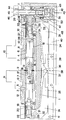
- the work spindle 2 is arranged, which is formed by the two spindle parts 3 and 4.
- the spindle part 3 has an external thread 5 and the spindle part 4 has an opposing external thread 6.
- the carriages 7 and 8 are guided in the vice body 1 in a manner known per se and each cooperate with spindle nuts with the external threads 5 and 6 of the spindle parts 3 and 4.
- the carriage 7 is shown in the advanced position, in which it reaches as far as the central plane 9, while the carriage 8 assumes the retracted position.
- the two slides 7 and 8 are generally arranged symmetrically with respect to the central plane 9, so that the jaws 10 and 11 on the slides 7 and 8 are also aligned symmetrically with the central plane 9. Since the slide has several grooves 12, it is possible to fix the jaws in different positions with respect to the slide. As a result, the distances between the jaws 10 and 11 can be adapted to different workpiece dimensions.
- the two spindle parts 3 and 4 of the screw spindle 2 are non-rotatably connected at the mutually facing ends by a polygonal bolt 13 which engages in corresponding recesses 14 and 15. However, the two screw spindles can move to a certain extent against each other in the axial direction.
- the gap is covered by the seal 16, which is held by the two sleeves 17.
- the seal 16 is formed in particular by two plate springs, which ensures a tight, play-free contact of the sleeves 17 at the ends of the threads 5 and 6.
- the sleeves 17 also serve to seal off the interior 18 from the threads 5 and 6 and to protect it from contamination.
- the outer ends of the screw spindle parts 3 and 4 are essentially of the same design.
- the screw spindle parts each have a recess 19 with a support ring 20.
- This ring 20 is supported on a spherical abutment 21 and this on the sleeve 22.
- This sleeve 22 is held in the short lever arm part 23 of the lever 24 in a threaded bush.
- the sleeve 22 can therefore for the purpose of adjustment be adjusted.
- the element 25 serves to fix the sleeve 22 in the short lever arm 23.
- the spindle part 4 receives in a square bore 26 the square bolt 27, via which the work spindle 2 is driven.
- This square bolt penetrates the screw sleeve 22, the abutment 21 and also the ring 20 on the side of the lever 31.
- a bevel gear 28 is placed on the outer end of the square bolt 27 and is mounted in the bearing 29 of the vice body 1 or angular drive housing 52.
- the screw sleeve 22 at the right end of the device shown is mounted in the short lever arm 30 of the lever 31.
- the two levers 24 and 31 are pivotable about the bearing bolts 32 and 33 and the long lever arms 34 and 35 are directed towards each other. They therefore run approximately parallel to the work spindle 2.
- the common drive member 38 which for example has the shape of a bolt and is mounted on the tabs 39 of the transmission lever 40, presses on the surfaces 36 and 37 of the long lever arms 34 and 35.
- the transmission lever 40 has the lever joint 41.
- a spherical support 43 is provided, on which the actuating force acts.
- the surfaces 36 and 37 can be arranged obliquely, as the drawing shows. However, these surfaces can also be flat, ie aligned parallel to the screw spindle axis, and can rest next to one another, for example in a fork-like manner on the drive member 38.
- the sleeve 44 is also rotatably mounted, which accommodates the rotatable auxiliary shaft 45.
- a crank 46 can engage at the upper end of this auxiliary shaft or the auxiliary shaft 45 can be rotated by a tool.
- the auxiliary shaft 45 which penetrates the sleeve 44, has a part with a screw thread 47 which engages in an internal thread of the element 48.
- This element 48 is also mounted in the angular drive housing 52.
- the storage is designated 49.
- the element 48 has a bevel gear 50 at the upper end, which cooperates with the bevel gear 28.
- the disengaging clutch 51 is arranged in a recess at the lower end of the element 48. This consists essentially of a ball, which is pressed into a recess of the element 48 by a spring, not shown.
- the lower end of the auxiliary shaft 45 interacts with the spherical support 43.
Description
Die Erfindung betrifft einen Schraubstock, insbesondere Maschinenschraubstock zum zentrischen Spannen von Werkstücken, mit einem Schraubstockkörper, in dem zwei Schlitten beweglich sind, die je einen Spannbacken tragen, mit einer gemeinsamen, zweigeteilten, mittels einer Kurbel antreibbaren Arbeitsspindel, mit einem Gewinde auf dem einen Spindelteil, das den einen Schlitten antreibt und einem gegenläufigen Gewinde auf dem anderen Spindelteil, das den anderen Schlitten antreibt, wobei beide Spindelteile gegeneinander unverdrehbar mit axialer Beweglichkeit gekuppelt sind, für jeden Spindelteil im Schraubstockkörper ein Widerlager vorgesehen ist und mit einer Einrichtung zur Kraftverstärkung der auf das Werkstück wirkenden Spannkräfte.The invention relates to a vice, in particular a machine vice for the central clamping of workpieces, with a vice body in which two slides are movable, each carrying a clamping jaw, with a common, two-part, spindle-driven work spindle with a thread on one spindle part which drives the one slide and an opposite thread on the other spindle part which drives the other slide, wherein both spindle parts are non-rotatably coupled with axial mobility, an abutment is provided for each spindle part in the vice body and with a device for strengthening the clamping forces acting on the workpiece.
Ein Maschinenschraubstock dieser Bauweise ist beispielsweise bekannt geworden durch die DE-B-12 20 800.A machine vice of this design has become known, for example, from DE-B-12 20 800.
Die Verwendung von zwei beweglichen Spannbacken, die beim Spannvorgang gegeneinander bewegbar sind, läßt ein zentrisches Spannen zu, das heißt, das Werkstück wird beim Spannvorgang in einer zentrischen Lage gehalten und nicht, wie bei Schraubstöcken mit einer Festbacke an einer beweglichen Backe gegen die Festbacke gepreßt und dadurch aus der Mittellage verschoben.The use of two movable clamping jaws, which can be moved against each other during the clamping process, allows a central clamping, i.e. the workpiece is held in a central position during the clamping process and not, as with vices with a fixed jaw on a movable jaw, pressed against the fixed jaw and thereby shifted from the middle position.
Bei dem bekannten Schraubstock ist eine Einrichtung zur Kraftverstärkung vorgesehen, die im wesentlichen aus einem mit Hydraulikflüssigkeit gefüllten Druckraum besteht, in die ein Primärkolben hineingedrückt wird. Ein wesentlich größerer Sekundärkolben leitet die Spannkraft weiter. Diese Kraftverstärkungseinrichtung sitzt an dem der Kurbel gegenüberliegenden Ende der Antriebsspindel und wirkt auf die zugehörige Spannbacke ein.In the known vice, a device for power amplification is provided, which essentially consists of a pressure chamber filled with hydraulic fluid, into which a primary piston is pressed. A much larger secondary piston transfers the clamping force. This force amplification device sits at the end of the drive spindle opposite the crank and acts on the associated clamping jaw.
Die einseitige Anordnung der Kraftverstärker hat den Nachteil, daß bei der Kraftverstärkung doch eine Veränderung der zentrischen Lage eintritt.The one-sided arrangement of the power amplifiers has the disadvantage that a change in the central position occurs when the power is amplified.
In der DE-A- 39 25 718 ist ein Schraubstock anderer Bauweise beschrieben, bei der zwischen den beiden Spindelteilen und den zugehörigen Schlitten je eine Einrichtung zur Kraftverstärkung vorgesehen ist. Auf diese Weise läßt sich erreichen, daß bei Betätigung der Spindel eine verstärkte Spannkraft auf die Spannbacken und damit auf das Werkstück ausgeübt wird, wobei auch die Kraftverstärkung symmetrisch angeordnet ist, so daß eine Verschiebung des Werkstückes aus der Mittellage vermieden wird.DE-A-39 25 718 describes a vice of a different design, in which between the two spindle parts and associated slide a device for power amplification is provided. In this way it can be achieved that when the spindle is actuated, an increased clamping force is exerted on the clamping jaws and thus on the workpiece, the force amplification also being arranged symmetrically, so that displacement of the workpiece from the central position is avoided.
Durch die Erfindung soll ein Schraubstock der eingangs angegebenen Gattung dahingehend weiter entwickelt werden, daß ein zentrisches Spannen auch unter der Wirkung der Kraftverstärkung erhalten wird, wobei angestrebt wird, die Bauweise einfach und übersichtlich zu halten.The invention is intended to further develop a vice of the type specified at the outset in such a way that a central clamping is also obtained under the effect of the force amplification, the aim being to keep the construction simple and clear.
Zur Lösung dieser Aufgabe geht die Erfindung aus von dem Schraubstock der eingangs angegebenen Gattung. Erfindungsgemäß wird vorgeschlagen, daß die beiden Widerlager beweglich gelagert sind und daß jedem Widerlager ein Hebel zugeordnet ist, der mit kurzem Hebelarm auf das Widerlager einwirkt und der an langem Hebelarm von der Kurbel angetrieben ist.To achieve this object, the invention is based on the vise of the type specified. According to the invention it is proposed that the two abutments are movably mounted and that each abutment is assigned a lever which acts on the abutment with a short lever arm and which is driven by the crank on a long lever arm.
Die Erfindung benützt zwar zur Erhöhung der Spannkraft ein gemeinsames Untersetzungsgetriebe in Form eines Hebelgetriebes, das über die Widerlager wirkt und das den Vorteil einer einfachen Bauweise und geringer Störungsanfälligkeit besitzt. Durch eine geeignete Kombination verschiedener Hebel läßt sich leicht die gewünschte Übersetzung der Kraft erhalten. Insbesondere ist leicht eine symmetrische Bauweise möglich, so daß auch die Kräfte, die auf die Backen wirken, gleich sind.Although the invention uses a common reduction gear in the form of a lever gear, which acts via the abutment and which has the advantage of a simple design and low susceptibility to failure, to increase the clamping force. The desired ratio of the force can easily be obtained by a suitable combination of different levers. In particular, a symmetrical design is easily possible, so that the forces acting on the jaws are the same.
Bei der Beanspruchung eines Hebelgestänges kommt es in aller Regel zu einer Verformung, insbesondere dann, wenn das Hebelgestänge auf Biegung beansprucht wird. Eine solche elastische Verformung ist aber für die angestrebte Wirkung keinesfalls nachteilig. Durch die elastisch nachgiebige Verformung wird ein Federeffekt erzielt, der sicherstellt, daß die Spannkraft am Werkstück auch dann noch im wesentlichen aufrechterhalten bleibt, wenn durch Verformung des Werkstückes oder anderer Bauteile ein Abfall der Spannkräfte eintreten würde. Bei Kraftverstärkern herkömmlicher Bauweise sind für diesen Zweck im allgemeinen zusätzliche Federelemente, z.B. Tellerfedern vorgesehen.When a lever linkage is stressed, deformation generally occurs, particularly when the lever linkage is stressed on bending. Such an elastic deformation is in no way disadvantageous for the desired effect. Due to the resilient deformation, a spring effect is achieved which ensures that the clamping force on the workpiece is essentially maintained even if the workpiece or other components were deformed to cause a drop in the clamping forces. In force boosters of conventional design, additional spring elements, for example cup springs, are generally provided for this purpose.
Das Untersetzungsgetriebe kann bei der Erfindung durch einen zusätzlichen Antrieb angetrieben sein, der dann betätigt wird, wenn am Schraubspindelantrieb die Endstellung erreicht ist. Besser ist es jedoch, wenn das Untersetzungsgetriebe bzw. das Hebelgestänge über die Kurbel antreibbar ist, wobei der Schraubspindelantrieb durch eine Ausrastkupplung abschaltbar ist.In the invention, the reduction gear can be driven by an additional drive, which is actuated when the end position is reached on the screw drive. However, it is better if the reduction gear or the lever linkage can be driven via the crank, the screw spindle drive being able to be switched off by a disengaging clutch.
Die Erfindung bevorzugt insbesondere eine symmetrische Anordnung der Hebel für die beiden Widerlager, derart, daß die langen Hebelarme gegeneinander gerichtet sind.The invention particularly prefers a symmetrical arrangement of the levers for the two abutments, such that the long lever arms are directed towards each other.
Bei dieser Bauweise kann dann an den Enden der langen Hebelarme ein gemeinsames Antriebsglied angreifen, wodurch erreicht wird, daß die beiden Widerlager gleichartig über die Kurbel vorgespannt und bewegt werden.In this construction, a common drive member can then engage at the ends of the long lever arms, whereby the two abutments are pretensioned and moved in the same way via the crank.
Das Antriebsglied sitzt insbesondere an einem Übertragungshebel, der sich etwa parallel zur Arbeitsspindel erstreckt und an dessen einem Ende das Hebelgelenk angeordnet ist und dessen freies Ende mit der Kurbel zusammenwirkt.The drive member sits in particular on a transmission lever which extends approximately parallel to the work spindle and at one end of which the lever joint is arranged and whose free end cooperates with the crank.
Im allgemeinen erweist es sich als günstig, wenn zur Betätigung des Hebelgestänges dieses rechtwinklig zur Achse der Schraubspindel angetrieben wird, während die Schraubspindelteile selbst zum Zwecke des Antriebs gedreht werden. Um dieses zu erreichen, empfiehlt es sich, ein Zahnradgetriebe vorzusehen, für die Weiterleitung der Antriebskraftkurbel auf die Schraubspindelteile. Bei einer bevorzugten Bauweise hierzu ist eine Hilfswelle für die Kurbel vorgesehen, von der die Arbeitsspindel über die Ausrastkupplung und ein Winkelgetriebe und von der das Hebelgestänge über ein Schraubengewinde antreibbar ist.In general, it proves to be advantageous if the lever linkage is actuated at right angles to the axis of the screw spindle, while the screw spindle parts themselves are rotated for the purpose of driving. In order to achieve this, it is advisable to provide a gear transmission for the transmission of the drive power crank to the screw spindle parts. In a preferred construction, an auxiliary shaft for the crank is provided, from which the work spindle can be driven via the disengaging clutch and an angular gear and from which the lever linkage can be driven via a screw thread.
Zur Errichtung der Justierung sind die Widerlager von einstellbaren Gewindebüchsen in den Hebeln getragen.The abutments are supported by adjustable threaded bushings in the levers for setting up the adjustment.
Es ist günstig, wenn die Hebel als Winkelhebel ausgebildet sind.It is advantageous if the levers are designed as angle levers.
In der Zeichnung ist ein Ausführungsbeispiel der Erfindung schematisch in einem Längsschnitt dargestellt.In the drawing, an embodiment of the invention is shown schematically in a longitudinal section.
In dem Schraubstockkörper 1 ist die Arbeitsspindel 2 angeordnet, die von den beiden Spindelteilen 3 und 4 gebildet wird. Der Spindelteil 3 besitzt ein Außengewinde 5 und der Spindelteil 4 ein gegenläufiges Außengewinde 6. Die Schlitten 7 und 8 sind in an sich bekannter Weise im Schraubstockkörper 1 geführt und wirken je mit Spindelmuttern mit den Außengewinden 5 und 6 der Spindelteile 3 und 4 zusammen.In the
In der Zeichnung ist der Schlitten 7 in der vorgeschobenen Stellung gezeigt, in der er bis an die Mittelebene 9 heranreicht, während der Schlitten 8 die zurückgezogene Stellung einnimmt. Bei praktischem Betrieb sind die beiden Schlitten 7 und 8 jedoch im allgemeinen symmetrisch zur Mittelebene 9 angeordnet, so daß die Backen 10 und 11 auf die Schlitten 7 und 8 ebenfalls symmetrisch zur Mittelebene 9 ausgerichtet sind. Da der Schlitten mehrere Nuten 12 besitzt, ist es möglich, die Backen in verschiedenen Stellungen bezüglich der Schlitten zu befestigen. Dadurch lassen sich die Abstände der Backen 10 und 11 an unterschiedliche Werkstückabmessungen anpassen.In the drawing, the carriage 7 is shown in the advanced position, in which it reaches as far as the central plane 9, while the
Die beiden Spindelteile 3 und 4 der Schraubspindel 2 sind an den einander zugewandten Enden durch einen Mehrkantbolzen 13, der in entsprechende Ausnehmungen 14 und 15 eingreift, unverdrehbar miteinander verbunden. Die beiden Schraubspindeln können sich jedoch in Achsrichtung ein gewisses Maß gegeneinander bewegen. Der Spalt wird durch die Dichtung 16 abgedeckt, die von den beiden Hülsen 17 gehalten wird. Die Dichtung 16 wird insbesondere von zwei Tellerfedern gebildet, die ein dichtes, spielfreies Anliegen der Hülsen 17 an den Enden der Gewinde 5 und 6 sicherstellt. Die Hülsen 17 dienen auch dazu, jeweils den Innenraum 18 vor den Gewinden 5 bzw. 6 abzuschließen und vor Verunreinigung zu schützen.The two
Die äußeren Enden der Schraubspindelteile 3 und 4 sind im wesentlichen gleichartig ausgebildet. Die Schraubspindelteile besitzen je eine Ausnehmung 19 mit einem Auflagerring 20. Dieser Ring 20 stützt sich auf ein ballig ausgebildetes Widerlager 21 und dieses auf der Hülse 22 ab. Diese Hülse 22 ist im kurzen Hebelarmteil 23 des Hebels 24 in einer Gewindebüchse gehalten. Die Hülse 22 kann daher zum Zwecke der Justierung verstellt werden. Das Element 25 dient der Fixierung der Hülse 22 im kurzen Hebelarm 23.The outer ends of the
Der Spindelteil 4 nimmt in einer Vierkantbohrung 26 den vierkantigen Bolzen 27 auf, über den die Arbeitsspindel 2 angetrieben wird. Dieser Vierkantbolzen durchdringt die Schraubhülse 22, das Widerlager 21 und auch den Ring 20 auf der Seite des Hebels 31. Auf das äußere Ende des Vierkantbolzens 27 ist ein Kegelzahnrad 28 aufgesetzt, das im Lager 29 des Schraubstockkörpers 1 bzw. Winkeltriebgehäuses 52 gelagert ist.The
Es ist klar, daß bei Drehung des Kegelzahnrads 28 der Vierkantbolzen 27 den Spindelteil 4 mitnimmt. Der Mehrkantbolzen 13 dreht dann den Schraubspindelteil 3.It is clear that when the
Auch die Schraubhülse 22 am rechten Ende der gezeigten Vorrichtung ist im kurzen Hebelarm 30 des Hebels 31 gelagert. Die beiden Hebel 24 und 31 sind um die Lagerbolzen 32 und 33 verschwenkbar und die langen Hebelarme 34 und 35 sind gegeneinander gerichtet. Sie verlaufen daher annähernd parallel zur Arbeitsspindel 2.The
Auf die Flächen 36 und 37 der langen Hebelarme 34 und 35 drückt das gemeinsame Antriebsglied 38, das beispielsweise die Form eines Bolzens besitzt und an den Laschen 39 des Übertragungshebels 40 gelagert ist. Der Übertragungshebel 40 besitzt das Hebelgelenk 41. Am freien Ende 42 ist ein balliges Auflager 43 vorgesehen, an dem die Betätigungskraft angreift. Die Flächen 36 und 37 können schräg angeordnet sein, wie dies die Zeichnung zeigt. Diese Flächen können aber auch eben, d.h. parallel zur Schraubspindelachse ausgerichtet sein und nebeneinander, z.B. gabelartig am Antriebsglied 38 anliegen.The
Im Winkeltriebgehäuse 52 ist ferner drehbar die Hülse 44 gelagert, die in sich die drehbare Hilfswelle 45 aufnimmt. Am oberen Ende dieser Hilfswelle kann eine Kurbel 46 angreifen bzw. läßt sich die Hilfswelle 45 durch ein Werkzeug drehen.In the
Die Hilfswelle 45, die die Hülse 44 durchdringt, besitzt einen Teil mit einem Schraubengewinde 47, der in ein Innengewinde des Elements 48 eingreift. Dieses Element 48 ist ebenfalls im Winkeltriebgehäuse 52 gelagert. Die Lagerung ist mit 49 bezeichnet. Das Element 48 besitzt am oberen Ende eine Kegelverzahnung 50, die mit dem Kegelzahnrad 28 zusammenwirkt.The
In einer Ausnehmung am unteren Ende des Elements 48 ist die Ausrastkupplung 51 angeordnet. Diese besteht im wesentlichen aus einer Kugel, die durch eine nicht näher dargestellte Feder in eine Ausnehmung des Elements 48 hineingedrückt wird.The disengaging
Das untere Ende der Hilfswelle 45 wirkt mit dem balligen Auflager 43 zusammen.The lower end of the
Wenn in der zurückgezogenen Stellung der Schlitten 7 und 8 die Hilfswelle 45 in geeigneter Richtung gedreht wird, bewegen sich die Schlitten 7 und 8 mit den Backen 10 und 11 gegeneinander. Diese Bewegung kommt dadurch zustande, daß die Hilfswelle 45 über die Ausrastkupplung 51 das Element 48 mitnimmt und über das Winkelgetriebe aus den Teilen 50 und 28 der Mehrkantbolzen 27 die Arbeitsspindel 2 antreibt. Haben die Backen 10 und 11 das nicht näher dargestellte Werkstück ergriffen, werden bei weiterer Drehung der Hilfswelle 45 die langen Hebelarme 34 und 35 gleichartig gegen das Antriebsglied 38 gedrückt. In diesem vorgespannten Zustand wird die Ausrastkupplung 51 den weiteren Vorschub beenden, und die Hilfswelle 45 wird mit ihrem Gewinde 47 bei weiterer Drehbewegung nach unten geschraubt. Dadurch wird das ballige Auflager 43 nach unten gedrückt und über das Hebelgestänge aus den Teilen 40, 24,31,32 und 33 werden die Widerlager 21 gegeneinander gedrückt, wodurch die erhöhte Spannkraft zustande kommt.When the
Claims (9)
- Vice, in particular a machine vice for clamping work pieces centrically, comprising a vice body (1) in which two slides (7,8) each carrying a clamping jaw (10,11) are movable, one common two-piece work spindle (3, 4) operable by means of a crank (46), a thread (5) on one spindle part (3) operating one slide (11) and a thread running in the opposite direction (6) on the other spindle part (4) operating the other slide (8), with both spindle parts being coupled such that they are locked against mutual rotation and axially movable, with each spindle part being provided with a thrust block (21) in the vice body and having a device for amplifying the clamping forces acting upon the work piece, characterized in that the two thrust blocks (21) are movably supported and that each thrust block (21) has been assigned one lever (24,31), the short lever arm (23,30) acting on the thrust block and the long lever arm (34,35) being operated on by the crank (46).
- Vice according to claim 1, characterized in that the reduction gearing (47,40,38) is operable via the crank (46), with the screw spindle drive mechanism (27) capable of being disconnected by means of a disengaging coupling (51).
- Vice according to one or more of the preceding claims, characterized in a symmetrical arrangement of the levers (24,31) for the two thrust blocks (21) in such a way that the long lever arms (34,35) are arranged opposite one another.
- Vice according to one or more of the preceding claims, characterized in that a common operating member (38) acts upon the long lever arms (34,35) at their ends.
- Vice according to one or more of the preceding claims, characterized by a transmission lever (40) extending approximately parallel to the work spindle (2) and at one end of which is arranged the lever joint (41) and the free end of which acts together with the crank (46).
- Vice according to one or more of the preceding claims, characterized by gearing (50,28) for transmitting the driving force of the crank (46) to the screw spindle parts (3,4) and the reduction gearing (47,40,38) respectively.
- Vice according to one or more of the preceding claims, characterized by an auxiliary shaft (45) for the crank (46), by which the work spindle (2) is operable via the disengaging coupling (51) and bevel gears (50,28), and by which the lever linkage (40,24,34) is operable via a screw thread (47).
- Vice according to one or more of the preceding claims, characterized in that the thrust blocks (21) are supported by adjustable threaded sleeves (22) provided in the levers (24,31).
- Vice according to one or more of the preceding claims, characterized in that the levers (24,31) are designed as angle levers.
Applications Claiming Priority (2)
| Application Number | Priority Date | Filing Date | Title |
|---|---|---|---|
| DE4105425A DE4105425A1 (en) | 1991-02-21 | 1991-02-21 | VICE, IN PARTICULAR MACHINE VICE FOR CENTRICALLY CLAMPING |
| DE4105425 | 1991-02-21 |
Publications (3)
| Publication Number | Publication Date |
|---|---|
| EP0499808A2 EP0499808A2 (en) | 1992-08-26 |
| EP0499808A3 EP0499808A3 (en) | 1992-11-25 |
| EP0499808B1 true EP0499808B1 (en) | 1994-06-22 |
Family
ID=6425568
Family Applications (1)
| Application Number | Title | Priority Date | Filing Date |
|---|---|---|---|
| EP92100951A Expired - Lifetime EP0499808B1 (en) | 1991-02-21 | 1992-01-22 | Vice with power amplifier |
Country Status (3)
| Country | Link |
|---|---|
| EP (1) | EP0499808B1 (en) |
| JP (1) | JPH04310374A (en) |
| DE (2) | DE4105425A1 (en) |
Families Citing this family (1)
| Publication number | Priority date | Publication date | Assignee | Title |
|---|---|---|---|---|
| DE102015119177A1 (en) * | 2015-11-06 | 2017-05-11 | Lang Technik Gmbh | Clamping device and method for clamping a workpiece |
Family Cites Families (6)
| Publication number | Priority date | Publication date | Assignee | Title |
|---|---|---|---|---|
| FR1054956A (en) * | 1951-02-28 | 1954-02-15 | vice | |
| GB775111A (en) * | 1954-06-23 | 1957-05-22 | Douglas Fraser & Sons Ltd | Self-centering mechanism for locating components of nominally circular cross-section |
| DE1141600B (en) * | 1956-11-16 | 1962-12-20 | Forkardt Paul Kg | Compressed air vice |
| DE1220800B (en) * | 1960-09-10 | 1966-07-07 | Hilma G M B H Maschf | Vice, especially machine vice |
| DE1982395U (en) * | 1967-10-30 | 1968-03-28 | Haff G M B H Geb | COMPRESSED AIR VICE. |
| DE3925718A1 (en) * | 1989-08-03 | 1991-02-07 | Saurer Allma Gmbh | Machine vice - has two carriages with jaw attachment moving on common two part threaded spindle |
-
1991
- 1991-02-21 DE DE4105425A patent/DE4105425A1/en not_active Withdrawn
-
1992
- 1992-01-22 DE DE59200246T patent/DE59200246D1/en not_active Expired - Fee Related
- 1992-01-22 EP EP92100951A patent/EP0499808B1/en not_active Expired - Lifetime
- 1992-02-19 JP JP4031643A patent/JPH04310374A/en active Pending
Also Published As
| Publication number | Publication date |
|---|---|
| DE4105425A1 (en) | 1992-08-27 |
| DE59200246D1 (en) | 1994-07-28 |
| EP0499808A3 (en) | 1992-11-25 |
| JPH04310374A (en) | 1992-11-02 |
| EP0499808A2 (en) | 1992-08-26 |
Similar Documents
| Publication | Publication Date | Title |
|---|---|---|
| EP0480299B1 (en) | Multiple clamping device for clamping at least two workpieces | |
| DE10026829C2 (en) | Device for clamping a workpiece with an uneven surface | |
| DE2257384C3 (en) | Chucks for lathes and the like machine tools | |
| DE4112547C2 (en) | ||
| DE3603618C1 (en) | Clamping device for use on machine tools | |
| DE3610671A1 (en) | Drill chuck | |
| EP0499808B1 (en) | Vice with power amplifier | |
| DE3619145C1 (en) | Chuck with two opposing jaws | |
| DE660950C (en) | Mandrel for machine tools | |
| EP0525501B1 (en) | Clamp drive, especially for machine vices | |
| DE1810722C3 (en) | Chuck | |
| EP0340602B1 (en) | Drive for a machine vice | |
| DE623815C (en) | ||
| DE2626557C3 (en) | Clamping device, in particular machine vice | |
| DE3509922C1 (en) | Clamping device for fastening a work holder or the like to a spindle | |
| DE4025745C2 (en) | ||
| DE1922682B2 (en) | Chuck for lathes and the like | |
| EP0049878B1 (en) | Mechanical clamping device for rotary jaw chucks or collets | |
| DE889856C (en) | Chuck for swivel jaws or the like. | |
| DE823385C (en) | Chuck, especially for clamping weak-walled workpieces | |
| DE1800271C3 (en) | Chucks door lathes | |
| DE2262383C3 (en) | Hollow spindle for clamping devices, in particular machine vices with mechanical drive and mechanical or hydraulic pressure intensifiers | |
| DE807156C (en) | Tapping device | |
| DE1090540B (en) | Stick for grinding, especially long waves | |
| DE1031171B (en) | Quill arranged resiliently in the workpiece spindle and axially sliding |
Legal Events
| Date | Code | Title | Description |
|---|---|---|---|
| PUAI | Public reference made under article 153(3) epc to a published international application that has entered the european phase |
Free format text: ORIGINAL CODE: 0009012 |
|
| AK | Designated contracting states |
Kind code of ref document: A2 Designated state(s): CH DE FR IT LI |
|
| PUAL | Search report despatched |
Free format text: ORIGINAL CODE: 0009013 |
|
| AK | Designated contracting states |
Kind code of ref document: A3 Designated state(s): CH DE FR IT LI |
|
| 17P | Request for examination filed |
Effective date: 19921209 |
|
| 17Q | First examination report despatched |
Effective date: 19931122 |
|
| GRAA | (expected) grant |
Free format text: ORIGINAL CODE: 0009210 |
|
| AK | Designated contracting states |
Kind code of ref document: B1 Designated state(s): CH DE FR IT LI |
|
| ET | Fr: translation filed | ||
| REF | Corresponds to: |
Ref document number: 59200246 Country of ref document: DE Date of ref document: 19940728 |
|
| ITF | It: translation for a ep patent filed |
Owner name: BUGNION S.P.A. |
|
| PLBE | No opposition filed within time limit |
Free format text: ORIGINAL CODE: 0009261 |
|
| STAA | Information on the status of an ep patent application or granted ep patent |
Free format text: STATUS: NO OPPOSITION FILED WITHIN TIME LIMIT |
|
| 26N | No opposition filed | ||
| PGFP | Annual fee paid to national office [announced via postgrant information from national office to epo] |
Ref country code: FR Payment date: 20010118 Year of fee payment: 10 |
|
| PGFP | Annual fee paid to national office [announced via postgrant information from national office to epo] |
Ref country code: DE Payment date: 20010323 Year of fee payment: 10 |
|
| PGFP | Annual fee paid to national office [announced via postgrant information from national office to epo] |
Ref country code: CH Payment date: 20010427 Year of fee payment: 10 |
|
| PG25 | Lapsed in a contracting state [announced via postgrant information from national office to epo] |
Ref country code: LI Free format text: LAPSE BECAUSE OF NON-PAYMENT OF DUE FEES Effective date: 20020131 Ref country code: CH Free format text: LAPSE BECAUSE OF NON-PAYMENT OF DUE FEES Effective date: 20020131 |
|
| PG25 | Lapsed in a contracting state [announced via postgrant information from national office to epo] |
Ref country code: DE Free format text: LAPSE BECAUSE OF NON-PAYMENT OF DUE FEES Effective date: 20020801 |
|
| REG | Reference to a national code |
Ref country code: CH Ref legal event code: PL |
|
| PG25 | Lapsed in a contracting state [announced via postgrant information from national office to epo] |
Ref country code: FR Free format text: LAPSE BECAUSE OF NON-PAYMENT OF DUE FEES Effective date: 20020930 |
|
| REG | Reference to a national code |
Ref country code: FR Ref legal event code: ST |
|
| PG25 | Lapsed in a contracting state [announced via postgrant information from national office to epo] |
Ref country code: IT Free format text: LAPSE BECAUSE OF NON-PAYMENT OF DUE FEES;WARNING: LAPSES OF ITALIAN PATENTS WITH EFFECTIVE DATE BEFORE 2007 MAY HAVE OCCURRED AT ANY TIME BEFORE 2007. THE CORRECT EFFECTIVE DATE MAY BE DIFFERENT FROM THE ONE RECORDED. Effective date: 20050122 |