EP0499532B1 - Verbesserungen und Vorrichtungen zur Befestigung von Zierleisten an Fahrzeugkarosserien sowie ihr Verfahren zur Durchführung und Herstellung - Google Patents
Verbesserungen und Vorrichtungen zur Befestigung von Zierleisten an Fahrzeugkarosserien sowie ihr Verfahren zur Durchführung und Herstellung Download PDFInfo
- Publication number
- EP0499532B1 EP0499532B1 EP19920400364 EP92400364A EP0499532B1 EP 0499532 B1 EP0499532 B1 EP 0499532B1 EP 19920400364 EP19920400364 EP 19920400364 EP 92400364 A EP92400364 A EP 92400364A EP 0499532 B1 EP0499532 B1 EP 0499532B1
- Authority
- EP
- European Patent Office
- Prior art keywords
- stud
- clips
- hole
- pin
- head
- Prior art date
- Legal status (The legal status is an assumption and is not a legal conclusion. Google has not performed a legal analysis and makes no representation as to the accuracy of the status listed.)
- Expired - Lifetime
Links
Images

Classifications
-
- F—MECHANICAL ENGINEERING; LIGHTING; HEATING; WEAPONS; BLASTING
- F16—ENGINEERING ELEMENTS AND UNITS; GENERAL MEASURES FOR PRODUCING AND MAINTAINING EFFECTIVE FUNCTIONING OF MACHINES OR INSTALLATIONS; THERMAL INSULATION IN GENERAL
- F16B—DEVICES FOR FASTENING OR SECURING CONSTRUCTIONAL ELEMENTS OR MACHINE PARTS TOGETHER, e.g. NAILS, BOLTS, CIRCLIPS, CLAMPS, CLIPS OR WEDGES; JOINTS OR JOINTING
- F16B5/00—Joining sheets or plates, e.g. panels, to one another or to strips or bars parallel to them
- F16B5/06—Joining sheets or plates, e.g. panels, to one another or to strips or bars parallel to them by means of clamps or clips
- F16B5/0607—Joining sheets or plates, e.g. panels, to one another or to strips or bars parallel to them by means of clamps or clips joining sheets or plates to each other
- F16B5/0621—Joining sheets or plates, e.g. panels, to one another or to strips or bars parallel to them by means of clamps or clips joining sheets or plates to each other in parallel relationship
- F16B5/065—Joining sheets or plates, e.g. panels, to one another or to strips or bars parallel to them by means of clamps or clips joining sheets or plates to each other in parallel relationship the plates being one on top of the other and distanced from each other, e.g. by using protrusions to keep contact and distance
-
- B—PERFORMING OPERATIONS; TRANSPORTING
- B29—WORKING OF PLASTICS; WORKING OF SUBSTANCES IN A PLASTIC STATE IN GENERAL
- B29C—SHAPING OR JOINING OF PLASTICS; SHAPING OF MATERIAL IN A PLASTIC STATE, NOT OTHERWISE PROVIDED FOR; AFTER-TREATMENT OF THE SHAPED PRODUCTS, e.g. REPAIRING
- B29C45/00—Injection moulding, i.e. forcing the required volume of moulding material through a nozzle into a closed mould; Apparatus therefor
- B29C45/0053—Injection moulding, i.e. forcing the required volume of moulding material through a nozzle into a closed mould; Apparatus therefor combined with a final operation, e.g. shaping
- B29C45/006—Joining parts moulded in separate cavities
-
- F—MECHANICAL ENGINEERING; LIGHTING; HEATING; WEAPONS; BLASTING
- F16—ENGINEERING ELEMENTS AND UNITS; GENERAL MEASURES FOR PRODUCING AND MAINTAINING EFFECTIVE FUNCTIONING OF MACHINES OR INSTALLATIONS; THERMAL INSULATION IN GENERAL
- F16B—DEVICES FOR FASTENING OR SECURING CONSTRUCTIONAL ELEMENTS OR MACHINE PARTS TOGETHER, e.g. NAILS, BOLTS, CIRCLIPS, CLAMPS, CLIPS OR WEDGES; JOINTS OR JOINTING
- F16B21/00—Means for preventing relative axial movement of a pin, spigot, shaft or the like and a member surrounding it; Stud-and-socket releasable fastenings
- F16B21/06—Releasable fastening devices with snap-action
- F16B21/08—Releasable fastening devices with snap-action in which the stud, pin, or spigot has a resilient part
- F16B21/082—Releasable fastening devices with snap-action in which the stud, pin, or spigot has a resilient part the stud, pin or spigot having two resilient parts on its opposite ends in order to connect two elements
-
- F—MECHANICAL ENGINEERING; LIGHTING; HEATING; WEAPONS; BLASTING
- F16—ENGINEERING ELEMENTS AND UNITS; GENERAL MEASURES FOR PRODUCING AND MAINTAINING EFFECTIVE FUNCTIONING OF MACHINES OR INSTALLATIONS; THERMAL INSULATION IN GENERAL
- F16B—DEVICES FOR FASTENING OR SECURING CONSTRUCTIONAL ELEMENTS OR MACHINE PARTS TOGETHER, e.g. NAILS, BOLTS, CIRCLIPS, CLAMPS, CLIPS OR WEDGES; JOINTS OR JOINTING
- F16B5/00—Joining sheets or plates, e.g. panels, to one another or to strips or bars parallel to them
- F16B5/12—Fastening strips or bars to sheets or plates, e.g. rubber strips, decorative strips for motor vehicles, by means of clips
- F16B5/123—Auxiliary fasteners specially designed for this purpose
-
- B—PERFORMING OPERATIONS; TRANSPORTING
- B29—WORKING OF PLASTICS; WORKING OF SUBSTANCES IN A PLASTIC STATE IN GENERAL
- B29C—SHAPING OR JOINING OF PLASTICS; SHAPING OF MATERIAL IN A PLASTIC STATE, NOT OTHERWISE PROVIDED FOR; AFTER-TREATMENT OF THE SHAPED PRODUCTS, e.g. REPAIRING
- B29C45/00—Injection moulding, i.e. forcing the required volume of moulding material through a nozzle into a closed mould; Apparatus therefor
- B29C45/0053—Injection moulding, i.e. forcing the required volume of moulding material through a nozzle into a closed mould; Apparatus therefor combined with a final operation, e.g. shaping
- B29C45/006—Joining parts moulded in separate cavities
- B29C2045/0065—Joining parts moulded in separate cavities the parts being interconnected before assembling by a breaking or shearing point
Definitions
- the invention relates to devices intended to fix on bodywork or vehicle bodies elongated parts such as trim strips or protective strips while being covered by these parts - which will be designated hereinafter, but in a way of course not limiting, by the word "hubcaps" - so as to be invisible from the outside of the body after fixing.
- the invention aims, above all, to remedy at least one of these drawbacks and preferably all.
- the fastening devices according to the invention are essentially characterized in that the foot of the pin has two elastic tabs symmetrical to one another with respect to an axial plane of the pin and extending radially from the end of this foot while being folded obliquely towards the central portion of the body of the pawn, the overall radial dimension of these legs being equal to the width of the hole for their most folded position and between this width and the length of the hole for their elastically relaxed position.
- This pin has respectively at its two axial ends two pairs of elastic tabs oriented axially in opposite directions and adapted to cooperate respectively with the edges of two coaxial holes not circulars hollowed out respectively in a part to be fixed and its support.
- the invention also relates to the methods of using fastening devices of the above kind, methods which are essentially characterized by the following steps: after having punched in the box a series of aligned non-circular holes, mounted on the hubcap to fix perforated plates as defined above, in each of which is mounted the head of a fixing pin as defined above, the spacings of the axes of the different pins being identical to those of the axes of the punched holes, the hubcap thus equipped is placed opposite the body so that the axes of the pins coincide with those of the holes and the hubcap is applied against the body, which automatically introduces the feet of the pins in the punched holes , the elastic relaxation of the first legs after their passage through said holes ensuring the locking of the assembly.
- the invention includes, apart from the main provisions, certain other provisions which are preferably used at the same time and which will be more explicitly discussed below.
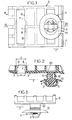
- Figures 1, 2 and 3, of this drawing show on an enlarged scale, respectively at the end, in cross section along II-II, Figure 1, and in side view according to arrow III of Figure 1, a device for binding established according to the invention as it appears at the outlet of its manufacturing mold.
- Figure 4 shows the same device in a cross section comparable to that of Figure 2, after axial insertion of the pin in the wafer.
- Figure 5 shows, again on an enlarged scale, a punched hole suitable for receiving the foot of the above pin.
- Figure 6 shows on a slightly reduced scale, in cross section, the assembly of a pin mounted on the sheet, and the facing plate mounted on a hubcap to be fixed on said sheet.
- Figures 7 and 8 show the above pawn on a larger scale than that of the first figures, respectively in axial section and in cross section according to VIII-VIII Figure 7.
- the shape in question corresponds to a circle C of diameter B extended radially by two ears R, the largest dimension of which is equal to A.
- the foot 5 of the pawn comprises two elastic legs 9 - said "first legs” below - which extend radially in a transverse direction T from the end of this foot and which are folded obliquely at about 45 ° on the axis X of the pin, towards the central portion of the body 14 of this pin.
- These legs 9 are elastically flexible around their fold lines located near the end of the foot.
- the direction T is perpendicular both to the axis of the pin and to the longitudinal direction L of the hub cap when the pin is mounted on a plate 3 itself mounted on this hub cap.
- the outline of the legs 9, projected onto a plane perpendicular to the axis of the pin, is such that these legs can pass through the ears R of each hole 7 without deformation when the direction T is oriented parallel to the length A of this hole, but not the circle C when this direction T is oriented parallel to the width B of said hole.
- the legs 9 are designed in such a way that, in the latter case, their axial introduction into the hole 7 from the outside of the body 2, has the effect, due to the simple sliding of the legs against the close edges of the hole corresponding to its width B, to retract said legs sufficiently by folding towards the axis X of the pin so that their axial crossing of said hole is possible, the radial elastic relaxation of the legs after the crossing in question ensuring the axial locking of the assembly.
- the tabs 9 elastically relax, while then taking support axially against the edge of the hole 7, which ensures the locking of the assembly.
- the assembly method which has just been indicated is particularly interesting in that it avoids the need to mount the pins in the holes 7 of the body before the presentation of the hubcap furnished with its plates opposite this checkout.
- the assembly is carried out in a single operation instead of two, which leads to a considerable saving of time.
- each pin 4 on the body 2 is easily removable.
- Said head 6 comprises two elastic tabs 10 - said "second legs" below - which extend radially in the transverse direction T, from the end of said head, and are folded obliquely on the axis X of the pin , towards the central portion of the body 14 of this pin, the angle of inclination of said legs on said axis here being a little less than 45 ° and for example of the order of 20 to 30 °.
- the mutual spacing e of these two flanges 11 is slightly less than the overall dimension E of the legs 10 in their normal state in the direction T (see FIGS. 1 and 7).
- These second tabs 10 are arranged in such a way that their axial introduction into the housing 8 has the effect, by virtue of their simple sliding against the flanges 11, of retracting them sufficiently by folding towards the axis of the pin to make possible their passage between these edges, the subsequent radial elastic relaxation of these lugs 10 then ensuring the axial locking of the mounting of the pin in the wafer.
- the housing 8 hollowed out in the plate 3 is bordered, in the longitudinal direction L of the hub cap when the plate is mounted thereon, by at least one recess 12 (FIG. 1) suitable for receiving the head 6 of the pin 4 by simple relative movement between plate and pin in said direction L, said head being able to be extracted by simple axial translation of said recess 12.
- the recess 12 is delimited in part by two axial longitudinal plane faces F whose mutual spacing is equal to the mutual spacing e of the two inside edges 11.
- the housing 8 is wider than the recess 12 in the direction T.
- the pin 4 comprises in its central zone a collar 13 in the form of a cup whose concavity is oriented towards the foot 5: the assembly is drawn in such a way that the edge of this cup 13 comes to rest against the body 2 just when the tabs 9 elastically relax at the end of their crossing of the corresponding hole 7.
- the sheet constituting the body is elastically clamped between the legs 9 and the cup 13, and the pin 4 is therefore securely fixed, without play, on this sheet.
- the central part of the body 14 of the pin which is located at the edges of the holes 7 at the end of assembly, is advantageously understood to have wings or legs extending transversely outwards at from said body, clean wings to come angularly into abutment against particular sections of said edges and to be able to be retracted by bending for one of the two possible directions of angular displacement of the pin relative to the sheet.
- the two wings 15 and 16 are surrounded, both axially and angularly, by any desirable clearances such as 17,18,19, allowing their bending around their roots.
- the very particular construction of the pin 4, comprising four elastically flexible tabs 9 and 10 all extending radially in the same direction T facilitates the obtaining of this pin by molding.
- the plate can comprise several parallel sets of housings 8 associated with at least one adjacent recess 12: preferably two such assemblies are provided for each plate, each cooperating with a pin 4, the two corresponding pins being then obtained molding simultaneously with said wafer 3.
- the material constituting the pins 4 and plates 3 is preferably a synthetic material such as an acetal resin.
- this shape is advantageous in that it makes it possible to compensate to a certain extent for the errors in the center distances between the punched holes 7, since it is possible to ensure a relative refocusing between each pin and each hole by sliding inclined surfaces of said pin against the edge of such a hole, when mounting the hubcap 3 on the body 2.
- This device has many advantages over those previously known, in particular as regards the simplicity of the implementation, and, in the preferred embodiments, the simplicity of manufacture.
Landscapes
- Engineering & Computer Science (AREA)
- General Engineering & Computer Science (AREA)
- Mechanical Engineering (AREA)
- Manufacturing & Machinery (AREA)
- Insertion Pins And Rivets (AREA)
- Connection Of Plates (AREA)
- Snaps, Bayonet Connections, Set Pins, And Snap Rings (AREA)
Claims (7)
- Vorrichtung an einer Fahrzeugkarosserie zum Befestigen einer Zierleiste mit, einerseits, einem Zapfen (4), von dem der Fuß (5) bestimmt ist, mit einem nicht kreisförmigen Loch zusammenzuarbeiten, das in die Karosserie gestanzt ist, wobei das Loch eine doppelte Symmetrie bezüglich jeweils zwei untereinander senkrechten Achsen mit einer großen Abmessung oder "Länge" (A) und einer kleinen Abmessung oder "Breite" (B) aufweist, und, andererseits, einem gelochten Plättchen, das auf der Zierleiste montiert ist und geeignet ist, auf entfernbare Weise den Kopf (6) des Zapfens aufzunehmen, dadurch gekennzeichnet, daß der Fuß (5) des Zapfens (4) zwei elastische Lappen (9) aufweist, die zueinander bezüglich einer axialen Ebene des Zapfens symmetrisch sind und sich vom Ende dieses Fußes aus radial erstrecken, wobei sie schräg bezüglich des zentralen Abschnittes des Körpers (14) des Zapfens zurückgefaltet sind, wobei die äußerlich all dieser Lappen (9) gemessene radiale Abmessung in ihrer am weitesten zurückgefalteten Position gleich der Breite (B) des Loches ist und in ihrer elastisch entspannten Position zwischen dieser Breite und der Länge (A) des Loches enthalten ist.
- Vorrichtung zum Befestigen gemäß Anspruch 1, dadurch gekennzeichnet, daß die Enden der elastischen Lappen (9) mit Rasten (91) versehen sind, von denen die vertieften Teile geeignet sind, durch Verklemmung mit den Rändern der Löcher am Ende der Montage zusammenzuwirken.
- Vorrichtung zum Befestigen gemäß irgendeinem der Ansprüche 1 und 2, dadurch gekennzeichnet, daß der Kopf (6) des Zapfens (4) zwei zweite elastische Lappen (10) aufweist, die zueinander symmetrisch bezüglich einer axialen Ebene des Zapfens sind und sich radial entlang derselben Richtung wie die ersten Lappen (9) vom Ende dieses Kopfes aus erstrecken, wobei sie schräg zum zentralen Teil des Körpers (14) des Zapfens geneigt sind, und daß jedes Plättchen (3) eine Unterbringung (8) aufweist, die geeignet ist, die Gesamtheit dieser beiden zweiten Lappen (10) aufzunehmen, wobei die Unterbringung zwei einspringende Ränder (11) aufweist, von denen der gegenseitige Abstand e kleiner als die gesamte äußerlich gemessene Querabmessung E der Gesamtheit der beiden zweiten Laschen (10) in ihrem Normalzustand ist, wobei diese zwei zweiten Laschen auf eine Weise angeordnet sind, daß ihr axiales Einführen in die obige Unterbringung (8) aufgrund ihres einfachen Gleitens über die Ränder zur Folge hat, daß sie ausreichend durch Biegen zur Achse des Zapfens eingezogen werden, um ihren Durchgang zwischen den Rändern möglich zu machen, wobei das folgende radiale elastische Entspannen dieser Lappen die axiale Verriegelung des Zusammenbaus sicherstellt.
- Vorrichtung zum Befestigen gemäß Anspruch 3, dadurch gekennzeichnet, daß die Unterbringung (8) des Plättchens (3) von zumindest einer Aussparung (12) eingefaßt ist, die geeignet ist, den Kopf (6) des Zapfens (4) durch einfaches relatives Verschieben zwischen dem Plättchen und dem Zapfen aufzunehmen, wobei die Aussparung genügend breit ist, damit der Kopf dann daraus durch einfache axiale Verschiebung herausgezogen werden kann.
- Vorrichtung zum Befestigen gemäß Anspruch 4, dadurch gekennzeichnet, daß die Aussparung (12) teilweise von zwei ebenen Seiten (F) begrenzt ist, von denen der gegenseitige Abstand gleich dem gegenseitigen Abstand e der beiden einspringenden Ränder (11) ist.
- Vorrichtung zum Befestigen gemäß irgendeinem der vorstehenden Ansprüche, dadurch gekennzeichnet, daß der Teil des Zapfens (4), der bestimmt ist, sich axial auf dem Niveau des Randes des Loches, welches diesen aufnimmt, zu befinden, einen ersten Flügel (15) aufweist, der geeignet ist, winklig in einem ersten Sinn durch Verklemmung zwischen einem Abschnitt (M) des Randes zur Anlage zu kommen und einen zweiten Flügel (16), der geeignet ist, seitlich in umgekehrter Winkelrichtung der vorstehenden gegen einen anderen Abschnitt (N) des Randes zur Anlage zu kommen, auf eine Weise, um eine genaue winklige Anordnung des Zapfens bezüglich des Loches zu ermöglichen, wobei die beiden fraglichen Flügel automatisch durch Falten zur Achse des Zapfens einziehbar sind, wenn man den Zapfen winklig in dem Loch im zweiten oben definierten Sinn verlagert.
- Verfahren zum Anwenden einer Vorrichtung zum Befestigen gemäß irgendeinem der vorstehenden Ansprüche, gekennzeichnet durch die Folge der folgenden Schritte: nachdem man in die Karosserie (2) eine Folge von ausgerichteten, nicht kreisrunden Löchern (7) gestanzt hat, montiert man auf der zu befestigenden Zierleiste (1) gelochte Plättchen (3), wie sie oben definiert worden sind, wobei in jeder von diesen der Kopf eines Zapfens zum Befestigen (4) montiert ist, wie er oben definiert worden ist, wobei die Abstände der Achsen der verschiedenen Zapfen identisch mit denjenigen der Achsen der gestanzten Löcher sind, man ordnet die so ausgerüstetete Zierleiste bezüglich der Karosserie so an, daß sich die Achsen der Zapfen mit denjenigen der Löcher decken und man bringt die Zierleiste an der Karosserie an, wodurch automatisch die Füße (5) der Zapfen in den gestanzten Löchern eingeführt werden, wobei das elastische Entspannen der ersten Lappen (9) nach ihrem Durchgang durch die Löcher die Verriegelung des Zusammenbaus sicherstellt.
Applications Claiming Priority (2)
| Application Number | Priority Date | Filing Date | Title |
|---|---|---|---|
| FR9101671A FR2672644B1 (fr) | 1991-02-13 | 1991-02-13 | Perfectionnements aux dispositifs pour fixer les enjoliveurs sur les carrosseries ainsi qu'a leurs procedes de mise en óoeuvre et de fabrication. |
| FR9101671 | 1991-02-13 |
Publications (2)
| Publication Number | Publication Date |
|---|---|
| EP0499532A1 EP0499532A1 (de) | 1992-08-19 |
| EP0499532B1 true EP0499532B1 (de) | 1997-07-23 |
Family
ID=9409663
Family Applications (1)
| Application Number | Title | Priority Date | Filing Date |
|---|---|---|---|
| EP19920400364 Expired - Lifetime EP0499532B1 (de) | 1991-02-13 | 1992-02-11 | Verbesserungen und Vorrichtungen zur Befestigung von Zierleisten an Fahrzeugkarosserien sowie ihr Verfahren zur Durchführung und Herstellung |
Country Status (4)
| Country | Link |
|---|---|
| EP (1) | EP0499532B1 (de) |
| DE (1) | DE69220977T2 (de) |
| ES (1) | ES2103905T3 (de) |
| FR (1) | FR2672644B1 (de) |
Families Citing this family (9)
| Publication number | Priority date | Publication date | Assignee | Title |
|---|---|---|---|---|
| FR2702720B1 (fr) * | 1993-03-19 | 1995-06-09 | Valeo Vision | Element pour le pre-montage d'une piece telle qu'un bandeau de style sur une partie de carrosserie d'un vehicule automobile, et piece l'incorporant. |
| US5758987A (en) * | 1995-09-18 | 1998-06-02 | Southco, Inc. | Snap-in fastener for flush-mounted panels |
| FR2752260B1 (fr) * | 1996-08-07 | 1998-09-11 | Ymos France | Serrure pour porte de vehicule automobile |
| DE10341981B4 (de) * | 2003-09-08 | 2005-08-04 | Decoma (Germany) Gmbh | Einrichtung zur Bereitstellung einer lösbaren Befestigung eines ersten Bauteils an einem zweiten Bauteil |
| FR2874351B1 (fr) * | 2004-08-20 | 2008-06-27 | Pascal Gons | Procede de moulage et assemblage de pieces et tete pour distributeur de produit notamment issue dudit procede |
| WO2010109499A1 (en) * | 2009-03-24 | 2010-09-30 | Uniteam Italia S.R.L. | Moulding method for the moulding of a component provided with snap-fit elements and component thereof |
| BR112014006468B1 (pt) | 2011-09-30 | 2020-09-15 | Illinois Tool Works Inc | Sistema e método para fabricação de um prendedor de duas partes |
| KR101820295B1 (ko) * | 2016-03-14 | 2018-01-19 | 현대자동차주식회사 | 차량용 클립 및 이를 적용한 대상체 고정 장치 |
| EP3527431A1 (de) * | 2018-02-19 | 2019-08-21 | DURA Automotive Holdings U.K., Ltd. | Dichtungsanordnung zur vorfixierung und vorausrichtung einer säulenblende an einer türstruktur eines kraftfahrzeugs und montagesystem mit einer dichtungsanordnung und einer säulenblende |
Family Cites Families (4)
| Publication number | Priority date | Publication date | Assignee | Title |
|---|---|---|---|---|
| US3775927A (en) * | 1972-05-26 | 1973-12-04 | Warren Fastener Corp | Self-retaining fastener |
| FR2296549A1 (fr) * | 1975-01-02 | 1976-07-30 | Peugeot & Renault | Element enjoliveur avec fixation integree |
| FR2428165A1 (fr) * | 1978-06-06 | 1980-01-04 | Rapid Sa | Attache pour l'assemblage d'au moins deux panneaux ou analogues |
| JPS5934732Y2 (ja) * | 1980-11-05 | 1984-09-26 | 株式会社ニフコ | 部品取付構造 |
-
1991
- 1991-02-13 FR FR9101671A patent/FR2672644B1/fr not_active Expired - Lifetime
-
1992
- 1992-02-11 EP EP19920400364 patent/EP0499532B1/de not_active Expired - Lifetime
- 1992-02-11 DE DE1992620977 patent/DE69220977T2/de not_active Expired - Fee Related
- 1992-02-11 ES ES92400364T patent/ES2103905T3/es not_active Expired - Lifetime
Also Published As
| Publication number | Publication date |
|---|---|
| DE69220977T2 (de) | 1998-03-05 |
| FR2672644A1 (fr) | 1992-08-14 |
| DE69220977D1 (de) | 1997-09-04 |
| ES2103905T3 (es) | 1997-10-01 |
| EP0499532A1 (de) | 1992-08-19 |
| FR2672644B1 (fr) | 1993-08-27 |
Similar Documents
| Publication | Publication Date | Title |
|---|---|---|
| CA1335498C (fr) | Dispositif d'assemblage pour elements demontables ou modulaires | |
| EP0081436B1 (de) | Verdichter- oder Turbinenrotor, dessen Rad die mit einem Fuss des Hammerkopftyps versehenen Schaufeln trägt, und Montageverfahren eines solchen Rotors | |
| FR2724428A1 (fr) | Organe de fixation par flexion | |
| EP0083289B1 (de) | Rotorrad eines Turbostrahltriebwerkes mit einer Vorrichtung zum axialen und radialen Befesten der Rotorschaufeln am Rotorrad | |
| FR2790046A1 (fr) | Dispositif de fixation de deux panneaux ou analogues forme de deux pieces cooperantes | |
| FR2742220A1 (fr) | Appareil pour deplier et fixer les ailettes d'un engin | |
| FR2651205A1 (fr) | Dispositif de verrouillage pour des generateurs solaires deployables. | |
| FR2898164A1 (fr) | Attache munie d'un pied d'encliquetage a enfoncer au travers du trou d'un panneau | |
| FR2741122A1 (fr) | Element de fixation | |
| EP0499532A1 (de) | Verbesserungen und Vorrichtungen zur Befestigung von Zierleisten an Fahrzeugkarosserien sowie ihr Verfahren zur Durchführung und Herstellung | |
| EP1072502B1 (de) | Abscherbare Gleitbefestigung für ein Kunststoffteil auf einem Tragelement | |
| FR2604475A1 (fr) | Paumelle a blocage axial de la broche pour porte ou fenetre | |
| FR2633021A1 (fr) | Dispositif de fixation d'une piece sur un panneau | |
| WO2018046813A1 (fr) | Platine support avec filtrage de vibrations d'un ventilateur, échangeur de chaleur, condenseur sur un élément structurel du corps d'un appareil ou véhicule a moteur et procédé de fabrication | |
| EP1515002B1 (de) | Verdrehsicherung für Turbinenstatorschaufeln in der Gehäusetrennebene | |
| EP3658790A1 (de) | Mutterkäfigsystem mit einem mutterkäfig und einem träger, auf dem der käfig montiert werden soll | |
| FR3122458A1 (fr) | Dispositif de fixation réversible par emboitement coaxial à encliquetage de deux éléments | |
| FR2572008A1 (fr) | Perfectionnements aux assemblages a mi-bois | |
| FR2733285A1 (fr) | Dispositif de fixation mecanique rigide destine a une rotule, ensemble le comprenant et procedes de montage et demontage | |
| EP0208582A1 (de) | Aufwickelspindel, insbesondere für einen Sicherheitsgurt | |
| WO2022079360A1 (fr) | Ensemble d'attache pour une aube de turbomachine | |
| FR2933243A1 (fr) | Dispositif d'obturation pour prise de courant. | |
| FR2549696A1 (fr) | Piege a insectes pret a monter | |
| FR2772819A1 (fr) | Semelle de reglage d'une gache de serrure de vehicule automobile | |
| FR2498272A1 (fr) | Collier de raccordement pour dispositif de fixation a baionnette |
Legal Events
| Date | Code | Title | Description |
|---|---|---|---|
| PUAI | Public reference made under article 153(3) epc to a published international application that has entered the european phase |
Free format text: ORIGINAL CODE: 0009012 |
|
| AK | Designated contracting states |
Kind code of ref document: A1 Designated state(s): DE ES GB IT |
|
| 17P | Request for examination filed |
Effective date: 19930204 |
|
| 17Q | First examination report despatched |
Effective date: 19940208 |
|
| GRAG | Despatch of communication of intention to grant |
Free format text: ORIGINAL CODE: EPIDOS AGRA |
|
| GRAH | Despatch of communication of intention to grant a patent |
Free format text: ORIGINAL CODE: EPIDOS IGRA |
|
| GRAH | Despatch of communication of intention to grant a patent |
Free format text: ORIGINAL CODE: EPIDOS IGRA |
|
| GRAA | (expected) grant |
Free format text: ORIGINAL CODE: 0009210 |
|
| AK | Designated contracting states |
Kind code of ref document: B1 Designated state(s): DE ES GB IT |
|
| GBT | Gb: translation of ep patent filed (gb section 77(6)(a)/1977) |
Effective date: 19970723 |
|
| REF | Corresponds to: |
Ref document number: 69220977 Country of ref document: DE Date of ref document: 19970904 |
|
| REG | Reference to a national code |
Ref country code: ES Ref legal event code: FG2A Ref document number: 2103905 Country of ref document: ES Kind code of ref document: T3 |
|
| ITF | It: translation for a ep patent filed | ||
| PGFP | Annual fee paid to national office [announced via postgrant information from national office to epo] |
Ref country code: ES Payment date: 19980209 Year of fee payment: 7 |
|
| PLBE | No opposition filed within time limit |
Free format text: ORIGINAL CODE: 0009261 |
|
| STAA | Information on the status of an ep patent application or granted ep patent |
Free format text: STATUS: NO OPPOSITION FILED WITHIN TIME LIMIT |
|
| 26N | No opposition filed | ||
| PG25 | Lapsed in a contracting state [announced via postgrant information from national office to epo] |
Ref country code: ES Free format text: LAPSE BECAUSE OF NON-PAYMENT OF DUE FEES Effective date: 19990212 |
|
| REG | Reference to a national code |
Ref country code: ES Ref legal event code: FD2A Effective date: 20010503 |
|
| REG | Reference to a national code |
Ref country code: GB Ref legal event code: IF02 |
|
| PG25 | Lapsed in a contracting state [announced via postgrant information from national office to epo] |
Ref country code: IT Free format text: LAPSE BECAUSE OF NON-PAYMENT OF DUE FEES Effective date: 20050211 |
|
| PGFP | Annual fee paid to national office [announced via postgrant information from national office to epo] |
Ref country code: DE Payment date: 20080331 Year of fee payment: 17 |
|
| PG25 | Lapsed in a contracting state [announced via postgrant information from national office to epo] |
Ref country code: DE Free format text: LAPSE BECAUSE OF NON-PAYMENT OF DUE FEES Effective date: 20090901 |
|
| PGFP | Annual fee paid to national office [announced via postgrant information from national office to epo] |
Ref country code: GB Payment date: 20100224 Year of fee payment: 19 |
|
| GBPC | Gb: european patent ceased through non-payment of renewal fee |
Effective date: 20110211 |
|
| PG25 | Lapsed in a contracting state [announced via postgrant information from national office to epo] |
Ref country code: GB Free format text: LAPSE BECAUSE OF NON-PAYMENT OF DUE FEES Effective date: 20110211 |