EP0499458A2 - Blatthandhabungsgerät - Google Patents
Blatthandhabungsgerät Download PDFInfo
- Publication number
- EP0499458A2 EP0499458A2 EP92301163A EP92301163A EP0499458A2 EP 0499458 A2 EP0499458 A2 EP 0499458A2 EP 92301163 A EP92301163 A EP 92301163A EP 92301163 A EP92301163 A EP 92301163A EP 0499458 A2 EP0499458 A2 EP 0499458A2
- Authority
- EP
- European Patent Office
- Prior art keywords
- stack
- pulley
- belt
- belt means
- belts
- Prior art date
- Legal status (The legal status is an assumption and is not a legal conclusion. Google has not performed a legal analysis and makes no representation as to the accuracy of the status listed.)
- Granted
Links
Images


Classifications
-
- B—PERFORMING OPERATIONS; TRANSPORTING
- B65—CONVEYING; PACKING; STORING; HANDLING THIN OR FILAMENTARY MATERIAL
- B65H—HANDLING THIN OR FILAMENTARY MATERIAL, e.g. SHEETS, WEBS, CABLES
- B65H29/00—Delivering or advancing articles from machines; Advancing articles to or into piles
- B65H29/12—Delivering or advancing articles from machines; Advancing articles to or into piles by means of the nip between two, or between two sets of, moving tapes or bands or rollers
-
- B—PERFORMING OPERATIONS; TRANSPORTING
- B65—CONVEYING; PACKING; STORING; HANDLING THIN OR FILAMENTARY MATERIAL
- B65H—HANDLING THIN OR FILAMENTARY MATERIAL, e.g. SHEETS, WEBS, CABLES
- B65H31/00—Pile receivers
- B65H31/30—Arrangements for removing completed piles
- B65H31/3027—Arrangements for removing completed piles by the nip between moving belts or rollers
-
- G—PHYSICS
- G07—CHECKING-DEVICES
- G07D—HANDLING OF COINS OR VALUABLE PAPERS, e.g. TESTING, SORTING BY DENOMINATIONS, COUNTING, DISPENSING, CHANGING OR DEPOSITING
- G07D11/00—Devices accepting coins; Devices accepting, dispensing, sorting or counting valuable papers
- G07D11/10—Mechanical details
- G07D11/14—Inlet or outlet ports
-
- B—PERFORMING OPERATIONS; TRANSPORTING
- B65—CONVEYING; PACKING; STORING; HANDLING THIN OR FILAMENTARY MATERIAL
- B65H—HANDLING THIN OR FILAMENTARY MATERIAL, e.g. SHEETS, WEBS, CABLES
- B65H2404/00—Parts for transporting or guiding the handled material
- B65H2404/20—Belts
- B65H2404/26—Particular arrangement of belt, or belts
- B65H2404/261—Arrangement of belts, or belt(s) / roller(s) facing each other for forming a transport nip
-
- B—PERFORMING OPERATIONS; TRANSPORTING
- B65—CONVEYING; PACKING; STORING; HANDLING THIN OR FILAMENTARY MATERIAL
- B65H—HANDLING THIN OR FILAMENTARY MATERIAL, e.g. SHEETS, WEBS, CABLES
- B65H2408/00—Specific machines
- B65H2408/10—Specific machines for handling sheet(s)
- B65H2408/13—Wall or kiosk dispenser, i.e. for positively handling or holding material until withdrawal by user
Definitions
- This invention relates to a sheet handling apparatus.
- the invention has application, for example, to a currency note stacking and presenting mechanism included in a cash dispenser unit of an automated teller machine (ATM).
- ATM automated teller machine
- a user inserts a customer identifying card into the machine and then enters certain data (such as codes, quantity of currency required, type of transaction, etc.) upon one or more keyboards included in a user console of the machine.
- the machine will then process the transaction, update the user's account to reflect the current transaction, dispense cash, when requested, from one or more currency cassettes mounted in the machine, and return the card to the user as part of a routine operation.
- a cash dispenser unit of an ATM typically includes at least one note picking mechanism for extracting notes one by one from an associated currency cassette, and a stacking and presenting mechanism for accumulating the extracted notes into a stack and then feeding the stack of notes to a delivery port or exit slot in the ATM from where the stack may be removed by a user of the ATM.
- the stack feeding means of a known stacking and presenting mechanism includes first and second endless belt means which are mounted in a supporting framework whereby part of the first belt means is in cooperative relationship with respect to part of the second belt means for the purpose of feeding the stack to the exit location, those portions of the first and second belt means adjacent the exit location respectively passing around cooperatively associated first and second pulley means.
- the axis of rotation of a first one of the pulley means is fixed relative to the supporting framework but, in order to enable stacks of different thicknesses to be accommodated between the first and second belt means, the axis of the second pulley means is movable.
- the second pulley means are mounted on pivotably mounted support means, spring means being attached to the support means for the purpose of urging the second pulley means towards the first pulley means.
- a disadvantage of the above mentioned known stacking and presenting mechanism is that the spring means tend to weaken, and possibly fail, after prolonged use, thereby detracting from the reliability of the mechanism.
- Another disadvantage of the known mechanism is that the gripping force applied by the belt means to the stack at the exit location tends to increase as the thickness of the stack increases, thereby detracting from the uniformity of the operational characteristics of the mechanism.
- a sheet handling apparatus including stacking means for accumulating sheets into a stack, and feeding means for feeding said stack to an exit location, said feeding means including first and second endless belt means which are mounted in a supporting framework whereby part of said first belt means is in cooperative relationship with respect to part of said second belt means for the purpose of feeding said stack to said exit location, those portions of said first and second belt means adjacent said exit location respectively passing around cooperatively associated first and second pulley means, said first pulley means having a first, fixed axis of rotation and said second pulley means having a second, movable axis of rotation with respect to said supporting framework, characterized in that said second pulley means are carried by support means rockably mounted about a third, fixed axis of rotation, said part of said second belt means being in cooperative engagement with third pulley means carried by said support means, and said third axis being located at an intermediate position with respect to said second and third pulley means, and said first and second belt means are resiliently stretchable and tensioned whereby
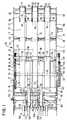
- the stacking and presenting mechanism 10 shown therein includes a supporting framework 11 having side walls 12 and 14.
- Two composite pulleys 16 and 18 are respectively rotatably mounted on two parallel shafts 20 and 22 which extend between the side walls 12 and 14, the axes of the shafts 20 and 22 lying in the same horizontal plane.
- the composite pulley 16 includes a first set of three operably related pulleys 26 spaced apart along the shaft 20, and two further operably related pulleys 28 which are interposed with respect to the pulleys 26 as seen in Fig. 1.
- the composite pulley 18 includes three operably related pulleys 30 which are similar to, and are correspondingly located with respect to, the pulleys 26, and two further pulleys 32 which are similar to, and are corresponding located with respect to, the pulleys 28.
- the composite pulleys 16 and 18 are of wide diameter, having a diameter of 6.4 centimetres.
- Two meshing gear wheels 34 and 36 (Fig. 1) are respectively secured to the composite pulleys 16 and 18, the gear wheel 34 being coupled via a gear system 38 to a reversible electric stepping motor 40 which serves to drive the composite pulleys 16 and 18.
- Three further shafts 42, 44 and 46 extend between the side walls 12 and 14 in an upper portion of the framework 11.
- Three sets of pulleys 48, 50 and 52 are respectively rotatably mounted on the shafts 42, 44 and 46, each of these sets comprising three pulleys which are correspondingly located with respect to the pulleys 26 and 30.
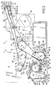
- the set of pulleys 52 is located adjacent an exit port 54 (Fig. 2) of the stacking and presenting mechanism 10, and the set of pulleys 50 is located at an intermediate position with respect to the sets of pulleys 52 and 48, as shown in Fig. 2.
- three pairs of arms 56 are independently rotatably mounted on a shaft 58 which extends between the side walls 12 and 14 in a position lower than the shaft 46.
- One pair of corresponding ends of each pair of arms 56 carry a respective shaft 60 extending between the arms 56, and the other ends of each pair of arms 56 carry a respective shaft 62 also extending between the arms 56.
- Three pulleys 64 are respectively mounted on the shafts 60, and three pulleys 66 are respectively mounted on the shafts 62, the pulleys 64 and the pulleys 66 being correspondingly located with respect to the pulleys 26, 30, 48, 50 and 52.
- a further shaft 68 extends between the side walls 12 and 14 and is positioned beneath the shaft 44, three further pulleys 70 being rotatably mounted on the shaft 68.
- the pulleys 70 are correspondingly located with respect to the pulleys 26, 30, 48, 50, 52, 64 and 66.
- Three resiliently stretchable endless belts 72 pass around the pulleys 30, 50 and 52, under the pulleys 48, over the pulleys 64 and partly around the peripheries of the pulleys 26 as seen in Fig. 2, each belt 72 being cooperatively associated with a set of correspondingly located pulleys 30, 50, 52, 48, 64 and 26.
- Three further resiliently stretchable endless belts 74 pass around the pulleys 26, 64 and 62, under the pulleys 50 and over the pulleys 70, again as seen in Fig. 2, each belt 74 being cooperatively associated with a set of correspondingly located pulleys 26, 64, 62, 50 and 70.
- the lower parts of the belts 72 extending between the pulleys 26 and 52 are respectively in cooperative engagement with the upper parts of the belts 74 extending between the pulleys 26 and 66.
- the said parts of the belts 72 are held in resilient engagement with the cooperating parts of the belts 74 by virtue of these parts of the belts 72 and 74 being deflected downwardly by the pulleys 50 and upwardly by the pulleys 64, and by virtue of the belts 72 and 74 being in a slightly tensioned condition.
- a stack of currency notes 76 comprising a variable number of notes can be fed to the exit port 54 of the mechanism 10 by virtue of being gripped between the cooperating parts of the belts 72 and 74.
- Located beneath the composite pulleys 16 and 18 are two shafts 78 and 80 (Fig. 2) which extend between the side walls 12 and 14.
- Two pairs of pulleys 82 and 84 (Fig. 2) are respectively rotatably mounted on the shafts 78 and 80, the pulleys of each pair being correspondingly located with respect to the pulleys 28 (Fig. 1) of the composite pulley 16.
- the pulleys 82 are of wide diameter, having a diameter of 6.4 centimetres.
- Two resiliently stretchable endless belts 86 pass around the pulleys 28 and 82 and partly around the peripheries of the pulleys 84, each belt 86 being cooperatively associated with a set of correspondingly located pulleys 28, 82 and 84.
- the stack 76 rests against the belts 86 with the lower long edges of the notes in the stack 76 being supported by arms 87 (hereinafter referred to as stripper arms 87).
- two further pairs of pulleys 88 and 90 are respectively rotatably mounted on two shafts 92 and 94 extending between the side walls 12 and 14, and another pair of pulleys 96 are secured on a drive shaft 98 extending between, and rotatably mounted with respect to, the side walls 12 and 14.
- the drive shaft 98 is driven by the electric motor 40 (Fig. 1) via a gear system (not shown).
- Two resiliently stretchable endless belts 100 pass around the pulleys 88, 90 and 96, and partially around the peripheries of the pulleys 82, each belt 100 being cooperatively associated with a set of correspondingly located pulleys 82, 88, 90 and 96.
- the upper parts of the belts 100 extending between the pulleys 88 and 96 are respectively in cooperative engagement with those parts of the belts 86 in contact with the pulleys 82.
- the said parts of the belts 100 are held in resilient engagement with the cooperating parts of the belts 86 by virtue of the belts 100 passing partly around the peripheries of the pulleys 82 with the belts 100 being in a slightly tensioned condition.
- a stack of rejected currency notes comprising a variable number of notes
- a rejected note container 102 hereinafter referred to as the purge bin 102
- the rejected notes being deposited in the purge bin 102 via an opening 104 in one side thereof.
- the leading edge of the stack of rejected notes is gripped by cooperating sets of foam rubber feed rolls 106 which, together with guide means 107, serve to feed the stack into the purge bin 102.
- the feed rolls 106 are driven by the motor 40, and the resilient nature of the rolls 106 enables them to feed a stack of notes of variable thickness.
- the passage of a stack of rejected currency notes into the purge bin 102 is sensed by optical sensing means 108.
- a pair of clamp arms 110, 112 are rotatably mounted on the shaft 22.
- the ends of the clamp arms 110, 112 remote from the shaft 22 carry a shaft 114 which extends between the arms 110, 112.
- a pair of pulleys 116 are rotatably mounted on the shaft 114, the pulleys 116 being correspondingly located with respect to the pulleys 32 (Fig. 1) of the composite pulley 18.
- Two upwardly extending support arms 118 are secured on the shaft 114, and two pairs of pivotal arms 120 are respectively pivotably mounted on the two support arms 118, each pair of pivotal arms 120 being pivotably mounted on a stud 122 secured to the upper end of the respective support arm 118.
- each pair of pivotal arms 120 remote from the respective support arm 118 carry a stud 124 on which is mounted a respective pulley 126, the two pulleys 126 being correspondingly located with respect to the pulleys 116 and 32.
- Two further resiliently stretchable endless belts 128 pass around the pulleys 126, 116, and 32, each belt 128 being cooperatively associated with a set of correspondingly located pulleys 126, 116 and 32.
- the belts 128 are in a slightly tensioned condition, and the lower parts of the belts 128 extending between the pulleys 126 and the pulleys 32 are deflected downwardly by the pulleys 116.
- the pivotal arms 120 are normally resiliently held by the tension of the belts 128 in the position shown in Fig. 2, with left hand edges (with reference to Fig. 2) of two notches 130 respectively formed in the lower edges of the pivotal arms 120 bearing against the shaft 114.
- the pivotal arms 120 may be pivoted to some extent relative to the clamp arms 110 in a clockwise direction (with reference to Fig. 2) about the axis of the studs 122, such clockwise pivotable movement being limited by engagement of the right hand edges of the notches 130 with the shaft 114.
- a stud 132 (Fig. 1) is secured to the outer surface of the side wall 14, and a cam 134 (not shown in Fig. 2) is rotatably mounted on the stud 132.
- Two cam tracks (not shown), in the form of arcuate recesses, are formed in the inner surface of the cam 134 facing the side wall 14.
- the cam 134 is driven by a reversible electric stepping motor 136 via a gear system 138, the gear system 138 engaging with a gear wheel 140 forming an integral part of the cam 134.
- a stud 142 secured to the outer face of the clamp arm 110 engages in one of the cam tracks formed in the cam 134.
- the clamp assembly 144 comprising the belts 128, the clamp and pivotal arms 110, 112; 120, and the pulleys 116, 126 is in the position shown in Fig. 2.
- pivotal movement of the assembly 144 in an anticlockwise direction (with reference to Fig. 2) about the axis of the shaft 22 is brought about by virtue of the engagement of the stud 142 in the relevant cam track in the cam 134.
- This pivotal movement continues until the belts 128 come into cooperative relationship with the belts 86 with the stack of notes 76 gripped between the belts 128 and 86, shortly after which the rotational movement of the cam 134 is stopped in a manner to be described later.
- the cooperating parts of the belts 128 and 86 extend between a location adjacent the peripheries of the pulleys 82 and a location at which the belts 128 and 86 are in cooperative relationship with respect to the peripheries of the pulleys 32. It should be understood that when the belts 128 are in cooperative relationship with the belts 86, the pulleys 116 deflect the belts 86 slightly so that the stack of currency notes 76 resting against the belts 86 is gripped resiliently between the belts 128 and 86 by virtue of the tension in the belts 86 as well as by virtue of the tension in the belts 128.
- the stack 76 can be fed by the belts 128 and 86 to the nip A of the belts 72 and 74 from where the stack 76 is fed by the belts 72 and 74 to the exit port 54, the approach of the stack 76 to the exit port 54 being sensed first by optical sensing means 146 (Fig. 2) positioned between the pulleys 50 and the pulleys 64 and then by further optical sensing means 148 (Fig. 2) positioned adjacent the exit port 54.
- the stack of notes 76 gripped between the belts 128 and 86 can be fed by the belts 128 and 86 to the nip B of the belts 86 and 100 from where the stack is fed by the belts 86 and 100 and the feed rolls 106 into the purge bin 102, the stripper arms 87 having first been pivoted out of the way into the position 87′ shown in chain outline in Fig. 2.
- the assembly 144 is pivoted in a clockwise direction back to its home position shown in Fig. 2.
- the return of the assembly 144 to its home position is sensed by optical sensing means 150 (Fig. 1) which is cooperatively located with respect to the clamp arm 112.
- the movement of the stripper arms 87 to the position 87′ is sensed by further optical sensing means 152 (Fig. 2).
- Another optical sensing means 154 is positioned in cooperative relationship with respect to a timing wheel 156 secured to the composite pulley 16, the sensing means 154 generating in operation a series of timing pulses in response to rotation of the composite pulleys 16 and 18.
- All of the belts 72, 74, 86, 100 and 128 are of a resiliently stretchable elastomeric material such as polyurethane or silicone rubber.
- the stacking and presenting mechanism 10 includes a conventional stacking wheel 158 which is arranged to rotate continuously in operation in a clockwise direction with reference to Fig. 2.
- the stacking wheel 158 comprises a plurality of stacking plates 160 spaced apart in parallel relationship along a stacking wheel shaft 162, each stacking plate 160 incorporating a series of curved tines 164.
- the shaft 162 extends between, and is rotatably mounted with respect to, the side walls 12 and 14, and the shaft 162 is driven via transmission means (not shown) by an electric motor 166.
- the stacking wheel 158 cooperates with the stripper arms 87 which are spaced apart along the shaft 92 and are secured thereto, the shaft 92 being rotatably mounted with respect to the side walls 12 and 14.
- Each stripper arm 87 is positioned between an adjacent pair of stacking plates 160. During a stacking operation, the stripper arms 87 are positioned as shown in solid outline in Fig. 2 with each stripper arm 87 extending into the space between adjacent stacking plates 160. In such operation, currency notes are fed one by one to the stacking wheel 158 by a transport mechanism 168. Each note enters between adjacent tines 164 of the stacking plates 160 and is carried partly around the axis of the stacking wheel 158, the note being stripped from the wheel 158 by the stripper arms 87 and being stacked against the belts 86 with a long edge of the note being supported by the stripper arms 87. Pivotal movement of the stripper arms 87 between their home position shown in solid outline in Fig.
- this link mechanism incorporating, a stud which engages in a second arcuate slot (not shown) formed in the face of the cam 134 facing the side wall 14.
- the transport mechanism 168 serves to feed currency notes from a selected pick module 170 (Fig. 5) to the stacking wheel 158.
- the mechanism 168 includes two sets of cooperating endless belts 172 and 174.
- the belts 172 are driven by a set of pulleys 176 mounted on a drive shaft 178, and the belts 174 are driven by a set of pulleys 180 mounted on a drive shaft 182, the shafts 178 and 182 being driven via transmission means (not shown) by the motor 166.
- each currency note fed to the transport mechanism 168 is gripped between the belts 172 and 174 and is fed by the belts 172 and 174 to the stacking wheel 158 where the note is deposited between adjacent tines 164 of the stacking plates 160.
- a multiple note detect means 184 is positioned part way along the cooperating parts of the belts 172 and 174 for the purpose of detecting the passage of superposed notes between the belts 172 and 174.
- the note stacking and presenting mechanism 10 forms part of a cash dispenser unit 186 of an in-lobby ATM.
- the mechanism 10 and the pick modules 170 are housed in a safe 188.
- Each of the pick modules 170 is arranged to pick currency notes one by one from an associated currency cassette 190, and is arranged to feed each note picked from the associated cassette 190 along a common feed path 192 to the transport mechanism 168 of the mechanism 10.
- Notes picked from one or more of the cassettes 190 are stacked by the mechanism 10 as previously described, and are then presented to a user of the ATM via the delivery port 54 formed in a user console 194 of the ATM.
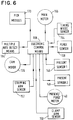
- the cash dispenser unit 186 includes electronic control means 198 (Fig. 6) which controls the operation of the motors 40, 136 and 166 and the pick modules 170, and to which are applied outputs of the sensor means 108, 146, 148, 150, 152 and 154 and the multiple note detect mechanism 184. It should be understood that the main drive motor 166 operates the stacking wheel 158, the drive shafts 178 and 182, and the pick modules 170.
- the main drive motor 166 is activated by the control means 198 so as to operate the transport mechanism 168 and cause the stacking wheel 158 to commence rotation.
- Currency notes are then picked one by one from a selected one or selected ones of the cassettes 190 in response to the application of signals to the relevant pick module or modules 170 by the control means 198.
- the picked notes are fed by the transport mechanism 168 to the stacking wheel 158 which stacks the notes in known manner against the stationary belts 86 so as to form the stack 76.
- the control means 198 deactivates the motor 166 and sends a signal to the motor 136 to activate the motor 136 so as to rotate the cam 134 from its home position.
- This rotation of the cam 144 brings about a pivotal movement of the clamp assembly 144 in an anticlockwise direction with reference to Fig. 2 so as to cause the stack of notes 76 to be clamped between the belts 128 and the belts 86; at the same time, the stripper arms 87 are moved to the position 87′ shown in chain outline in Fig. 2 in which the arms 87 are no longer in engagement with, or in a path of movement of, the stack of notes 76.
- the control means 198 deactivates the motor 136, so as to stop the cam 134, in response to the sensor means 152 sensing the stripping arms 87 reaching the position 87′.
- control means 198 sends a signal to the motor 40 so as to activate the motor 40 in such a sense as to cause the belts 128 and 86 to feed the stack of notes 76 to the nip A of the belts 72 and 74 from where the stack 76 is fed by the belts 72 and 74 to the exit port 54 of the ATM.
- the sensor means 146 senses first the leading edge of the stack 76 and then the trailing edge of the stack 76. A predetermined time after the trailing edge of the stack of notes is sensed by the sensor means 146, as determined by the application of timing pulses to the electronic control means 198 by the timing wheel sensor 154, the control means 198 deactivates the motor 40 so as to stop the stack 76 in a delivery position in which part of the stack projects through the exit port 54 and part of the stack 76 is held between the belts 72 and 74 as shown in Fig. 4.
- control means 198 causes the operation of the motor 40 to be reversed so as to cause the stack 76 to be withdrawn back into the dispenser unit 186 and deposited in the purge bin 102.
- the stack of notes can be readily removed from the user console 194 by the user of the ATM.
- the sensor means 148 senses whether or not a stack of notes is positioned at the exit port 54. If the presented stack 76 is not removed from the console 194 by the user of the ATM within a predetermined period of time, then, as with the case of a spread out stack, the electronic control means 198 causes the stack 76 to be withdrawn into the dispenser unit 186 and deposited in the purge bin 102.
- the control means 198 activates the motor 136 in the reverse sense so as to bring about a reverse rotation of the cam 134 and thereby cause the stripper arms 87 and the clamp assembly 144 to be returned to their home positions shown in solid outline in Fig. 2. It will be appreciated that this movement of the stripper arms 87 and clamp assembly 144 is brought about by virtue of the engagement of the stud 142, and the stud of the link mechanism (not shown) associated with the stripper arms 87, in the cam tracks (not shown) of the cam 134. Activation of the motor 136 in the reverse sense is terminated when the sensor means 150 senses the return of the clamp arm 112 to its home, non-clamping position.
- the rockably mounted pulleys 64 and 66 associated with the resiliently stretchable belts 72 and 74 provide a simple yet highly reliable and effective means for feeding and gripping a stack of notes of variable thickness at the exit port 54.
- the tensioned and stretchable nature of the belts 72 and 74 enables a stack of notes of variable thickness to be firmly gripped between the belts 72 and 74 for the whole of the feeding distance between the nip A and the exit port 54.
- a stack of notes up to 6 millimetres in thickness (approximately 40 notes or more, depending on the condition of the notes) can be fed between the belts 72 and 74.
- the pulleys 26 have a diameter which is substantially greater than that of the pulleys 52 and 66 (6 .4 centimetres as compared with 2.1 centimetres).
- the stack of notes 76 will be fed to the purge bin 102.
- the motor 136 is temporarily activated as previously described so as to move the stripper arms 87 to the position 87′ and the clamp assembly 144 to the clamping position in which the stack of notes 76 is clamped between the belts 128 and 86.
- control means 198 activates the motor 40 in such a sense as to cause the belts 128 and 86 to drive the stack of notes 72 to the nip B of the belts 86 and 100, from where the stack is fed by the belts 86 and 100 and the rolls 106 into the purge bin 102.
- the sensor means 108 senses the leading edge of the stack.
- the electronic control means 198 deactivates the motor 40 and temporarily activates the motor 136 in the reverse sense for the purpose of returning the stripper arms 87 and the clamping assembly 144 to their home positions.
- a further advantage of the stacking and presenting mechanism 10 described above is that, by virtue of the fact that a plurality of pairs of arms 56 are independently rotatably mounted on the shaft 58 and are respectively associated with a plurality of endless belts 74, the stack 76 is firmly gripped at the exit slot 54 between the belts 72 and 74, even though the thickness of the stack 76 may vary across its width (i.e. across the dimension of the stack 76 parallel to the axis of the shaft 58) due to slight variations in thickness across the width of individual notes.
Landscapes
- Engineering & Computer Science (AREA)
- Mechanical Engineering (AREA)
- Physics & Mathematics (AREA)
- General Physics & Mathematics (AREA)
- Delivering By Means Of Belts And Rollers (AREA)
- Pile Receivers (AREA)
Applications Claiming Priority (2)
| Application Number | Priority Date | Filing Date | Title |
|---|---|---|---|
| GB9103104 | 1991-02-14 | ||
| GB919103104A GB9103104D0 (en) | 1991-02-14 | 1991-02-14 | Sheet handling apparatus |
Publications (3)
| Publication Number | Publication Date |
|---|---|
| EP0499458A2 true EP0499458A2 (de) | 1992-08-19 |
| EP0499458A3 EP0499458A3 (en) | 1993-03-03 |
| EP0499458B1 EP0499458B1 (de) | 1995-07-12 |
Family
ID=10690003
Family Applications (1)
| Application Number | Title | Priority Date | Filing Date |
|---|---|---|---|
| EP92301163A Expired - Lifetime EP0499458B1 (de) | 1991-02-14 | 1992-02-12 | Blatthandhabungsgerät |
Country Status (4)
| Country | Link |
|---|---|
| US (1) | US5267826A (de) |
| EP (1) | EP0499458B1 (de) |
| DE (1) | DE69203359T2 (de) |
| GB (1) | GB9103104D0 (de) |
Cited By (5)
| Publication number | Priority date | Publication date | Assignee | Title |
|---|---|---|---|---|
| EP0535543A3 (en) * | 1991-09-30 | 1994-06-01 | Hitachi Ltd | Paper sheet conveying device and automatic cash handling apparatus |
| EP1548661A3 (de) * | 2003-12-27 | 2006-02-08 | LG N-Sys. Inc. | Medienausgabeeinheit |
| WO2006048217A3 (en) * | 2004-11-02 | 2006-07-13 | Siemens Ag | Mail processing system and method of loading articles with reduced speed |
| DE102008030878A1 (de) * | 2008-06-30 | 2009-12-31 | Giesecke & Devrient Gmbh | Vorrichtung und Verfahren für die Annahme oder Ausgabe von Banknoten |
| WO2010010126A3 (de) * | 2008-07-22 | 2010-08-05 | Siemens Aktiengesellschaft | Übergabevorrichtung für postsendungen |
Families Citing this family (17)
| Publication number | Priority date | Publication date | Assignee | Title |
|---|---|---|---|---|
| US5458051A (en) * | 1993-11-29 | 1995-10-17 | G. S. Blodgett Corporation | Belt cooking apparatus |
| US5803227A (en) * | 1995-06-06 | 1998-09-08 | International Game Technology | Bill stacker |
| GB9521615D0 (en) * | 1995-10-21 | 1996-01-03 | At & T Global Inf Solution | Stack transport device |
| GB9623046D0 (en) * | 1996-11-06 | 1997-01-08 | Ncr Int Inc | Escrow storage device |
| DE19648173B4 (de) * | 1996-11-21 | 2005-04-28 | Kolbus Gmbh & Co Kg | Vorrichtung zum Fördern von Produkten wie Druckbogenstapel |
| US6371368B1 (en) * | 1998-11-23 | 2002-04-16 | Diebold, Incorporated | Automated transaction machine |
| RU2149817C1 (ru) * | 1999-04-07 | 2000-05-27 | Открытое акционерное общество "Чебоксарский приборостроительный завод "ЭЛАРА" | Устройство для выдачи листов |
| GB2369230B (en) * | 2000-11-01 | 2005-01-19 | Lg Electronics Inc | A clutch system and a control method of media dispenser |
| RU2191737C2 (ru) * | 2000-12-22 | 2002-10-27 | Открытое акционерное общество "Чебоксарский приборостроительный завод "ЭЛАРА" | Устройство для выдачи листов |
| US7140607B2 (en) * | 2002-10-18 | 2006-11-28 | Diebold Self-Service Systems Division Of Diebold, Incorporated | Cash dispensing automated banking machine with note unstacking and validation |
| KR100608078B1 (ko) * | 2004-07-16 | 2006-08-08 | 엘지엔시스(주) | 매체자동지급기 |
| KR101016245B1 (ko) * | 2005-04-27 | 2011-05-18 | 노틸러스효성 주식회사 | 금융자동화기기의 출금장치 |
| JP4582787B2 (ja) * | 2005-06-17 | 2010-11-17 | 株式会社ユニバーサルエンターテインメント | 紙幣処理装置 |
| EP2249319A1 (de) * | 2005-07-27 | 2010-11-10 | MEI, Inc. | Banknotenhandhabungsvorrichtung |
| US7641193B2 (en) * | 2006-10-31 | 2010-01-05 | Hewlett-Packard Development Company, L.P. | Sheet bending |
| US8366107B2 (en) * | 2010-08-26 | 2013-02-05 | Ncr Corporation | Media presenter |
| US10872506B2 (en) * | 2018-12-19 | 2020-12-22 | Hyosung TNS Inc. | Automated teller machine |
Family Cites Families (13)
| Publication number | Priority date | Publication date | Assignee | Title |
|---|---|---|---|---|
| US2531253A (en) * | 1947-01-10 | 1950-11-21 | Jr Norman F Carden | Attachment for presses |
| DE1238401B (de) * | 1963-01-16 | 1967-04-06 | Ralfs Kg Org | Vorrichtung zum UEberleiten von Schriftgut in Bandfoerderanlagen |
| US3942785A (en) * | 1974-11-25 | 1976-03-09 | Xerox Corporation | Self-actuating sheet inverter reverser |
| JPS528900A (en) * | 1975-07-10 | 1977-01-24 | Tokyo Electric Co Ltd | Note transfer system |
| US4320854A (en) * | 1978-07-26 | 1982-03-23 | Tokyo Shibaura Denki Kabushiki Kaisha | Automatic cash issue machine |
| JPS6050696B2 (ja) * | 1980-09-04 | 1985-11-09 | ロ−レルバンクマシン株式会社 | 紙葉類集積装置 |
| NL8503203A (nl) * | 1985-11-21 | 1987-06-16 | Oce Nederland Bv | Inrichting voor het transporteren van een bundel vellen. |
| GB2197279B (en) * | 1986-11-06 | 1990-01-17 | Ncr Co | Sheet feeding apparatus |
| GB2209518B (en) * | 1987-09-10 | 1991-09-04 | Ncr Co | Sheet handling apparatus. |
| GB8819768D0 (en) * | 1988-08-19 | 1988-09-21 | Ncr Co | Sheet handling apparatus |
| DE3881690T2 (de) * | 1988-09-07 | 1993-12-23 | Ibm | Verfahren zur Steuerung zweier verbundener Transportmittel und eine auf diese Art gesteuerte Maschine, insbesondere ein persönlicher Bankautomat. |
| GB8825756D0 (en) * | 1988-11-03 | 1988-12-07 | Ncr Co | Sheet handling apparatus |
| GB8915126D0 (en) * | 1989-06-30 | 1989-08-23 | Ncr Co | Apparatus for stacking articles in a container |
-
1991
- 1991-02-14 GB GB919103104A patent/GB9103104D0/en active Pending
- 1991-12-23 US US07/812,599 patent/US5267826A/en not_active Expired - Lifetime
-
1992
- 1992-02-12 DE DE69203359T patent/DE69203359T2/de not_active Expired - Fee Related
- 1992-02-12 EP EP92301163A patent/EP0499458B1/de not_active Expired - Lifetime
Cited By (8)
| Publication number | Priority date | Publication date | Assignee | Title |
|---|---|---|---|---|
| EP0535543A3 (en) * | 1991-09-30 | 1994-06-01 | Hitachi Ltd | Paper sheet conveying device and automatic cash handling apparatus |
| EP1548661A3 (de) * | 2003-12-27 | 2006-02-08 | LG N-Sys. Inc. | Medienausgabeeinheit |
| US7464928B2 (en) | 2003-12-27 | 2008-12-16 | Lg N-Sys Inc. | Media discharging unit for media dispenser |
| WO2006048217A3 (en) * | 2004-11-02 | 2006-07-13 | Siemens Ag | Mail processing system and method of loading articles with reduced speed |
| US8082060B2 (en) | 2004-11-02 | 2011-12-20 | Siemens Aktiengesellschaft | Mail processing system and method of loading articles with reduced speed |
| DE102008030878A1 (de) * | 2008-06-30 | 2009-12-31 | Giesecke & Devrient Gmbh | Vorrichtung und Verfahren für die Annahme oder Ausgabe von Banknoten |
| US8167135B2 (en) | 2008-06-30 | 2012-05-01 | Giesecke & Devrient Gmbh | Apparatus and method for accepting or dispensing bank notes |
| WO2010010126A3 (de) * | 2008-07-22 | 2010-08-05 | Siemens Aktiengesellschaft | Übergabevorrichtung für postsendungen |
Also Published As
| Publication number | Publication date |
|---|---|
| EP0499458A3 (en) | 1993-03-03 |
| DE69203359T2 (de) | 1996-04-11 |
| EP0499458B1 (de) | 1995-07-12 |
| GB9103104D0 (en) | 1991-04-03 |
| DE69203359D1 (de) | 1995-08-17 |
| US5267826A (en) | 1993-12-07 |
Similar Documents
| Publication | Publication Date | Title |
|---|---|---|
| EP0499458B1 (de) | Blatthandhabungsgerät | |
| US5335484A (en) | Sheet handling apparatus | |
| EP0616963B1 (de) | Apparat zum Handhaben von Bögen | |
| US4822018A (en) | Sheet handling apparatus | |
| US4955964A (en) | Sheet handling apparatus | |
| US4971310A (en) | Paper sheet takeout apparatus | |
| US5597996A (en) | Cash dispensing apparatus (ATM) and method for separating rejected bank notes | |
| EP0367519B1 (de) | Appaparat zum Handhaben von Blättern | |
| US4739982A (en) | Sheet separating apparatus | |
| EP0471578B1 (de) | Blatthandhabungsvorrichtung | |
| EP0510798B1 (de) | Vorrichtung zum Behandeln von Blättern | |
| EP0256859A2 (de) | Dokumentenspender | |
| EP0517404B1 (de) | Vorrichtung zum Behandeln von Blättern | |
| JP2001240294A (ja) | 紙葉類集積装置および紙葉類収納庫および紙葉類取扱装置 | |
| US6135440A (en) | Sheet feeding apparatus | |
| KR100339739B1 (ko) | 현금자동지급기의미인도또는잔류지폐회수장치 | |
| JP5329259B2 (ja) | 紙葉類取扱装置 | |
| JP2756538B2 (ja) | シート処理装置 | |
| JPH0450637B2 (de) | ||
| JP2759194B2 (ja) | シート取扱装置 | |
| JP5208802B2 (ja) | 紙葉類取扱装置 | |
| JP3502179B2 (ja) | 紙幣払出装置における札揃え装置 | |
| JPH09278214A (ja) | 紙葉類払出し機 | |
| JPH06180779A (ja) | 用紙処理装置 | |
| JPH0438652B2 (de) |
Legal Events
| Date | Code | Title | Description |
|---|---|---|---|
| PUAI | Public reference made under article 153(3) epc to a published international application that has entered the european phase |
Free format text: ORIGINAL CODE: 0009012 |
|
| AK | Designated contracting states |
Kind code of ref document: A2 Designated state(s): DE FR GB |
|
| PUAL | Search report despatched |
Free format text: ORIGINAL CODE: 0009013 |
|
| AK | Designated contracting states |
Kind code of ref document: A3 Designated state(s): DE FR GB |
|
| 17P | Request for examination filed |
Effective date: 19930828 |
|
| RAP1 | Party data changed (applicant data changed or rights of an application transferred) |
Owner name: AT&T GLOBAL INFORMATION SOLUTIONS INTERNATIONAL IN |
|
| 17Q | First examination report despatched |
Effective date: 19941209 |
|
| GRAA | (expected) grant |
Free format text: ORIGINAL CODE: 0009210 |
|
| AK | Designated contracting states |
Kind code of ref document: B1 Designated state(s): DE FR GB |
|
| REF | Corresponds to: |
Ref document number: 69203359 Country of ref document: DE Date of ref document: 19950817 |
|
| ET | Fr: translation filed | ||
| PLBE | No opposition filed within time limit |
Free format text: ORIGINAL CODE: 0009261 |
|
| 26N | No opposition filed | ||
| REG | Reference to a national code |
Ref country code: FR Ref legal event code: CD |
|
| REG | Reference to a national code |
Ref country code: GB Ref legal event code: IF02 |
|
| PGFP | Annual fee paid to national office [announced via postgrant information from national office to epo] |
Ref country code: GB Payment date: 20021218 Year of fee payment: 12 |
|
| PGFP | Annual fee paid to national office [announced via postgrant information from national office to epo] |
Ref country code: FR Payment date: 20030129 Year of fee payment: 12 |
|
| REG | Reference to a national code |
Ref country code: GB Ref legal event code: 746 Effective date: 20030114 |
|
| PGFP | Annual fee paid to national office [announced via postgrant information from national office to epo] |
Ref country code: DE Payment date: 20030310 Year of fee payment: 12 |
|
| REG | Reference to a national code |
Ref country code: FR Ref legal event code: D6 |
|
| PG25 | Lapsed in a contracting state [announced via postgrant information from national office to epo] |
Ref country code: GB Free format text: LAPSE BECAUSE OF NON-PAYMENT OF DUE FEES Effective date: 20040212 |
|
| PG25 | Lapsed in a contracting state [announced via postgrant information from national office to epo] |
Ref country code: DE Free format text: LAPSE BECAUSE OF NON-PAYMENT OF DUE FEES Effective date: 20040901 |
|
| GBPC | Gb: european patent ceased through non-payment of renewal fee |
Effective date: 20040212 |
|
| PG25 | Lapsed in a contracting state [announced via postgrant information from national office to epo] |
Ref country code: FR Free format text: LAPSE BECAUSE OF NON-PAYMENT OF DUE FEES Effective date: 20041029 |
|
| REG | Reference to a national code |
Ref country code: FR Ref legal event code: ST |