EP0496982B1 - Poussoir en métal léger muni d'une armature anti-usure à matrice austénitique - Google Patents
Poussoir en métal léger muni d'une armature anti-usure à matrice austénitique Download PDFInfo
- Publication number
- EP0496982B1 EP0496982B1 EP91120741A EP91120741A EP0496982B1 EP 0496982 B1 EP0496982 B1 EP 0496982B1 EP 91120741 A EP91120741 A EP 91120741A EP 91120741 A EP91120741 A EP 91120741A EP 0496982 B1 EP0496982 B1 EP 0496982B1
- Authority
- EP
- European Patent Office
- Prior art keywords
- light metal
- tappet
- steel plate
- hardened
- steel
- Prior art date
- Legal status (The legal status is an assumption and is not a legal conclusion. Google has not performed a legal analysis and makes no representation as to the accuracy of the status listed.)
- Expired - Lifetime
Links
- 229910000831 Steel Inorganic materials 0.000 title claims description 41
- 239000010959 steel Substances 0.000 title claims description 41
- 229910052751 metal Inorganic materials 0.000 title claims description 24
- 239000002184 metal Substances 0.000 title claims description 24
- 239000011159 matrix material Substances 0.000 title claims description 6
- 239000000463 material Substances 0.000 claims description 8
- 238000000034 method Methods 0.000 claims description 8
- 238000002485 combustion reaction Methods 0.000 claims description 7
- 238000005121 nitriding Methods 0.000 claims description 7
- 229910000760 Hardened steel Inorganic materials 0.000 claims description 6
- OKTJSMMVPCPJKN-UHFFFAOYSA-N Carbon Chemical compound [C] OKTJSMMVPCPJKN-UHFFFAOYSA-N 0.000 claims description 4
- 229910052799 carbon Inorganic materials 0.000 claims description 4
- 229910000789 Aluminium-silicon alloy Inorganic materials 0.000 claims description 3
- 229910052782 aluminium Inorganic materials 0.000 claims description 3
- XAGFODPZIPBFFR-UHFFFAOYSA-N aluminium Chemical compound [Al] XAGFODPZIPBFFR-UHFFFAOYSA-N 0.000 claims description 3
- 229910045601 alloy Inorganic materials 0.000 claims description 2
- 239000000956 alloy Substances 0.000 claims description 2
- 239000000919 ceramic Substances 0.000 claims description 2
- 238000010438 heat treatment Methods 0.000 claims description 2
- 238000004519 manufacturing process Methods 0.000 claims description 2
- 229920003023 plastic Polymers 0.000 claims description 2
- 239000004033 plastic Substances 0.000 claims description 2
- 238000005480 shot peening Methods 0.000 claims description 2
- 239000006185 dispersion Substances 0.000 claims 3
- 229910000838 Al alloy Inorganic materials 0.000 claims 1
- 239000004411 aluminium Substances 0.000 claims 1
- 150000003839 salts Chemical class 0.000 claims 1
- 238000009434 installation Methods 0.000 description 3
- 238000001556 precipitation Methods 0.000 description 3
- IJGRMHOSHXDMSA-UHFFFAOYSA-N Atomic nitrogen Chemical compound N#N IJGRMHOSHXDMSA-UHFFFAOYSA-N 0.000 description 2
- 229910001092 metal group alloy Inorganic materials 0.000 description 2
- 238000005482 strain hardening Methods 0.000 description 2
- 229910000851 Alloy steel Inorganic materials 0.000 description 1
- 238000009792 diffusion process Methods 0.000 description 1
- 239000000835 fiber Substances 0.000 description 1
- 239000007789 gas Substances 0.000 description 1
- 238000005461 lubrication Methods 0.000 description 1
- 239000007769 metal material Substances 0.000 description 1
- 229910052757 nitrogen Inorganic materials 0.000 description 1
- 239000002244 precipitate Substances 0.000 description 1
- 230000003014 reinforcing effect Effects 0.000 description 1
- 238000007711 solidification Methods 0.000 description 1
- 230000008023 solidification Effects 0.000 description 1
- 239000007858 starting material Substances 0.000 description 1
- 230000000930 thermomechanical effect Effects 0.000 description 1
- 229920001187 thermosetting polymer Polymers 0.000 description 1
Images
Classifications
-
- F—MECHANICAL ENGINEERING; LIGHTING; HEATING; WEAPONS; BLASTING
- F01—MACHINES OR ENGINES IN GENERAL; ENGINE PLANTS IN GENERAL; STEAM ENGINES
- F01L—CYCLICALLY OPERATING VALVES FOR MACHINES OR ENGINES
- F01L1/00—Valve-gear or valve arrangements, e.g. lift-valve gear
- F01L1/12—Transmitting gear between valve drive and valve
- F01L1/14—Tappets; Push rods
- F01L1/16—Silencing impact; Reducing wear
-
- F—MECHANICAL ENGINEERING; LIGHTING; HEATING; WEAPONS; BLASTING
- F01—MACHINES OR ENGINES IN GENERAL; ENGINE PLANTS IN GENERAL; STEAM ENGINES
- F01L—CYCLICALLY OPERATING VALVES FOR MACHINES OR ENGINES
- F01L1/00—Valve-gear or valve arrangements, e.g. lift-valve gear
- F01L1/20—Adjusting or compensating clearance
- F01L1/22—Adjusting or compensating clearance automatically, e.g. mechanically
- F01L1/24—Adjusting or compensating clearance automatically, e.g. mechanically by fluid means, e.g. hydraulically
- F01L1/245—Hydraulic tappets
- F01L1/25—Hydraulic tappets between cam and valve stem
-
- F—MECHANICAL ENGINEERING; LIGHTING; HEATING; WEAPONS; BLASTING
- F01—MACHINES OR ENGINES IN GENERAL; ENGINE PLANTS IN GENERAL; STEAM ENGINES
- F01L—CYCLICALLY OPERATING VALVES FOR MACHINES OR ENGINES
- F01L2301/00—Using particular materials
-
- Y—GENERAL TAGGING OF NEW TECHNOLOGICAL DEVELOPMENTS; GENERAL TAGGING OF CROSS-SECTIONAL TECHNOLOGIES SPANNING OVER SEVERAL SECTIONS OF THE IPC; TECHNICAL SUBJECTS COVERED BY FORMER USPC CROSS-REFERENCE ART COLLECTIONS [XRACs] AND DIGESTS
- Y10—TECHNICAL SUBJECTS COVERED BY FORMER USPC
- Y10T—TECHNICAL SUBJECTS COVERED BY FORMER US CLASSIFICATION
- Y10T29/00—Metal working
- Y10T29/49—Method of mechanical manufacture
- Y10T29/49229—Prime mover or fluid pump making
- Y10T29/49298—Poppet or I.C. engine valve or valve seat making
- Y10T29/49304—Valve tappet making
Definitions
- the invention initially relates to a light metal tappet, in particular for the valve control of an internal combustion engine, with a tappet base body and a steel plate anchored on the contact surface for the control cams of the valve control, which has a hardened surface.
- Such light metal tappets as described, for example, in EP 0 030 780 B1, are exposed to relatively large temperature fluctuations from -30 ° C. during a cold start to approximately 130 ° C. during operation of an internal combustion engine.
- the problem here is the possibly different thermal expansion of the materials used.
- the steel plate anchored as a wear-resistant insert in a light metal plunger has good wear properties, it tends to detach when subjected to a corresponding thermal load. The thermal load capacity is therefore limited.
- Another technical disadvantage is that the installation space in the form of a relatively wide edge as a functional surface or as a cam contact surface, which is contacted by the control cam of a valve control, is lost.
- the object of the present invention is to provide a light metal tappet with an anchored steel plate, the surface of which has high ductility with high wear resistance and hardness.
- the steel plate consists of an austenitic, carbon-precipitation hardened base material, which has the same coefficient of expansion as aluminum, with a nitrided surface, a further Solidification is given by the fact that the surface of the steel plate is additionally work hardened.
- the work hardening of the surface of the steel plate is carried out by shot peening.
- the steel plate is welded to a plunger base body with a thin-walled cup shirt, the cup shirt consisting of an alloyed aluminum material, in particular AlSi 18 CuMgNi, and having a wall thickness of approximately 0.6 to 2.5 mm.
- the thermal expansion coefficients of the tappet base body and the steel plate are almost the same, and that the tappet base body consists of ceramic, plastic, thermoset or fiber reinforced light metal material.
- the steel plate is provided with holding teeth on its underside facing the plunger base body.
- the invention further relates to a method for producing a light metal tappet, in particular for the valve control of an internal combustion engine, with a tappet base body and a steel plate anchored on the contact surface for the cams of the valve control, which has a hardened surface, which is part of the object of the invention
- a light metal plunger can be manufactured with an anchored steel plate.
- a steel plate having an austenitic matrix is carburized and precipitation hardened and the surface facing the control cam is then nitrided, it being advantageous for the surface to be nitrided during the heat treatment or for the surface to be additionally work hardened, nitriding can be carried out in a gas stream, in a nitriding bath or in a plasma process.
- a high-alloy, austenitic and martensite-free steel is used, which can additionally be hardened with carbon precipitation, bath nitrided or cold worked.
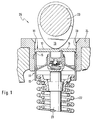
- valve control 25 of a combustion engine essentially consists of a control cam 19 which acts against the surface 16 of a tappet 10.
- the control cam 19 in turn is arranged on a camshaft 23 in a rotationally fixed manner.
- the plunger 10 is not one in a sliding guide 20
- Cylinder head 24 shown in detail can be moved up and down and acts on the side facing away from the control cam 19 against the valve stem 21 of a valve, not shown.
- a valve spring 22 is assigned to the valve stem 21 and ensures the resetting of the tappet 10.
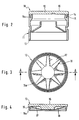
- the plunger 10 shown in detail in FIG. 2 consists of a light metal alloy, for example AlSi 18 CuMgNi, and has a plunger body 11 in which a steel plate 12 is anchored or welded.
- the plunger or cup body 11 has a plunger housing or cup shirt 13 pointing away from the steel plate 12, which is provided with an annular groove 14 toward the steel plate 12. In this annular groove 14, the steel plate 12 can be pressed, cast or pressed with holding teeth 15 having brackets 15a.
- the steel plate 12 consists of an austenitic matrix which is hardened like a carbon precipitate. On its surface 16 facing away from the tappet body 11, the steel plate 12 is nitrided, i. H. enriched with nitrogen. The surface 16 thereby receives a wear layer which is firmly connected to the matrix by diffusion. To further increase the wear resistance, the surface 16 can be work hardened.
- the steel plate 12 is provided on its inside 17 with stiffening elements 18 directed outward in the form of spokes.
- a steel plate 12 consists of a high-alloy steel, for example X5CrNi18-9. This steel has almost the same coefficient of thermal expansion as the above-mentioned light metal alloy of the plunger 10. Due to the austenitic matrix, the steel plate 12 has a high ductility and is particularly wear-resistant due to the nitriding and work hardening of the surface 16 on the contact surface of the control cam 19 and is suitable for installation in a cylinder head 24, not shown, with a valve control 25 of an internal combustion engine.
Landscapes
- Engineering & Computer Science (AREA)
- Mechanical Engineering (AREA)
- General Engineering & Computer Science (AREA)
- Valve-Gear Or Valve Arrangements (AREA)
- Valve Device For Special Equipments (AREA)
- Heat Treatment Of Articles (AREA)
Claims (18)
- Poussoir en métal léger, en particulier pour la commande de soupapes d'un moteur à combustion interne, comprenant un corps de base de poussoir ainsi qu'une plaque en acier à surface durcie qui est ancrée sur la face de contact pour les cames de commande de soupapes, caractérisé en ce que la plaque en acier (12) est constituée par une matière de base austénitique durcie par précipitation de carbures, qui a le même coefficient de dilatation que l'aluminium et qui comprend une surface nitrurée (16).
- Poussoir en métal léger selon la revendication 1, caractérisé en ce que la surface (16) de la plaque en acier (12) est en outre écrouie.
- Poussoir en métal léger selon la revendication 2, caractérisé en ce que la surface (16) de la plaque en acier (12) est écrouie par grenaillage.
- Poussoir en métal léger selon la revendication 1, caractérisé en ce que la plaque en acier (12) est soudée au corps de base (11) du poussoir comprenant une chemise (13) en forme de cuvette à paroi mince.
- Poussoir en métal léger selon les revendications 1 à 4, caractérisé en ce que la chemise (13) en forme de cuvette est réalisée en un alliage d'aluminium, notamment AISi 18 CuMgNi, et présente une épaisseur de paroi comprise à peu près entre 0,6 et 2,5 mm.
- Poussoir en métal léger selon les revendications 1 à 4, caractérisé en ce que la plaque en acier (12) est réalisée en un acier austénitique fortement allié et exempt de martensite, notamment X5CrNi18 9.
- Poussoir en métal léger selon les revendications 1 à 6, caractérisé en ce que les coefficients de la dilatation thermique du corps de base (11) du poussoir et de la plaque en acier (12) sont approximativement identiques.
- Poussoir en métal léger selon la revendication 1, caractérisé en ce que le corps de base (11) du poussoir est réalisé en un métal léger renforcé d'une matière céramique, plastique ou duroplastique, ou de fibres.
- Poussoir en métal léger selon les revendications 1 à 7, caractérisé en ce que la plaque en acier (12) comprend, sur sa surface inférieure faisant face au corps de base (11) du poussoir, des éléments de retenue (15a) munis de dents de retenue (15).
- Poussoir en métal léger dans lequel est ancrée une plaque en acier à trempe superficielle selon les revendications 1 à 9, caractérisé en ce que le matériau de base est en acier durci par précipitation de carbures.
- Poussoir en métal léger dans lequel est ancrée une plaque en acier à trempe superficielle selon les revendications 1 à 10, caractérisé en ce que le matériau de base est un acier nitruré au bain.
- Poussoir en métal léger dans lequel est ancrée une plaque en acier à trempe superficielle selon les revendications 1 à 9 et 10 ou 11, caractérisé en ce que le matériau de base est un acier écroui.
- Méthode de fabrication d'un poussoir en métal léger, en particulier pour la commande de soupapes d'un moteur à combustion interne, comprenant un corps de base de poussoir ainsi qu'une plaque en acier à surface durcie qui est ancrée sur la face de contact pour les cames de commande de soupapes, caractérisée en ce qu'une plaque en acier comprenant une matrice austénitique est carburée et durcie par précipitation, et que la surface faisant face à la came de commande est ensuite nitrurée.
- Méthode selon la revendication 13, caractérisée en ce que la surface est nitrurée pendant le traitement thermique.
- Méthode selon la revendication 13 ou 14, caractérisée en ce que la surface est en outre écrouie.
- Méthode selon l'une ou plusieurs des revendications 13 à 15, caractérisée en ce que la nitruration se fait dans un courant de gaz.
- Méthode selon l'une ou plusieurs des revendications 13 à 15, caractérisée en ce que la nitruration se fait dans un bain de sel de nitruration.
- Méthode selon l'une ou plusieurs des revendications 13 à 15, caractérisée en ce que la nitruration se fait par un procédé au plasma.
Applications Claiming Priority (2)
| Application Number | Priority Date | Filing Date | Title |
|---|---|---|---|
| DE4102988A DE4102988C1 (fr) | 1991-02-01 | 1991-02-01 | |
| DE4102988 | 1991-02-01 |
Publications (2)
| Publication Number | Publication Date |
|---|---|
| EP0496982A1 EP0496982A1 (fr) | 1992-08-05 |
| EP0496982B1 true EP0496982B1 (fr) | 1994-02-23 |
Family
ID=6424143
Family Applications (1)
| Application Number | Title | Priority Date | Filing Date |
|---|---|---|---|
| EP91120741A Expired - Lifetime EP0496982B1 (fr) | 1991-02-01 | 1991-12-03 | Poussoir en métal léger muni d'une armature anti-usure à matrice austénitique |
Country Status (4)
| Country | Link |
|---|---|
| US (1) | US5184583A (fr) |
| EP (1) | EP0496982B1 (fr) |
| JP (1) | JPH0559913A (fr) |
| DE (2) | DE4102988C1 (fr) |
Families Citing this family (9)
| Publication number | Priority date | Publication date | Assignee | Title |
|---|---|---|---|---|
| JPH05202706A (ja) * | 1992-01-29 | 1993-08-10 | Daido Steel Co Ltd | エンジンバルブおよびその製造方法 |
| US5361648A (en) * | 1992-04-07 | 1994-11-08 | Nsk Ltd. | Rolling-sliding mechanical member |
| GB9221817D0 (en) * | 1992-10-16 | 1992-12-02 | Automotive Products Plc | A differential mechanism |
| GB2273139B (en) * | 1992-11-12 | 1996-05-15 | Ford Motor Co | Low friction valve train for an internal combustion engine |
| DE4428309A1 (de) * | 1993-08-24 | 1995-03-02 | Schaeffler Waelzlager Kg | Tassenförmiger Ventilstößel |
| DE29501151U1 (de) * | 1995-01-25 | 1995-03-02 | INA Wälzlager Schaeffler KG, 91074 Herzogenaurach | Stößel mit einer geteilten Hemdfläche |
| DE19509665A1 (de) * | 1995-03-17 | 1996-09-19 | Schaeffler Waelzlager Kg | Mechanischer Ventilstößel |
| JPH11132012A (ja) * | 1997-10-29 | 1999-05-18 | Fuji Oozx Inc | 軽金属製タペット及びその製造方法 |
| WO2023154505A1 (fr) * | 2022-02-14 | 2023-08-17 | Awa Forged Composites, Llc | Procédé de conception et de production de poussoirs en polymère renforcé par des fibres |
Family Cites Families (9)
| Publication number | Priority date | Publication date | Assignee | Title |
|---|---|---|---|---|
| US3502057A (en) * | 1966-02-24 | 1970-03-24 | Earl A Thompson | Alloy,article of manufacture,and process |
| US4367701A (en) * | 1979-12-05 | 1983-01-11 | Eaton Corporation | Acting valve gear |
| DE3409235A1 (de) * | 1984-03-14 | 1985-09-19 | Motomak Motorenbau, Maschinen- u. Werkzeugfabrik, Konstruktionen GmbH, 8070 Ingolstadt | Aeusseres fuehrungsteil fuer einen ventilstoessel fuer verbrennungskraftmaschinen |
| DE3519015C2 (de) * | 1985-05-25 | 1996-04-11 | Schaeffler Waelzlager Kg | Ventilstößel für Verbrennungskraftmaschinen |
| JPS63109151A (ja) * | 1986-10-27 | 1988-05-13 | Hitachi Ltd | 高硬度複合材およびその製造方法 |
| JPS63289306A (ja) * | 1987-05-22 | 1988-11-25 | 日本特殊陶業株式会社 | 摺動部品の製造法 |
| DE3721677A1 (de) * | 1987-07-01 | 1989-01-12 | Irm Antriebstech Gmbh | Tassenstoessel mit hydraulischem ventilspielausgleich und verfahren zum herstellen eines solchen |
| US4909198A (en) * | 1988-03-01 | 1990-03-20 | Toyota Jidosha Kabushiki Kaisha | Aluminum alloy valve lifter with sprayed coating and method of producing same |
| DE3920729A1 (de) * | 1989-06-24 | 1991-01-10 | Gmb Giesserei & Maschinenbau B | Tassenstoesselkoerper fuer ventilstoessel |
-
1991
- 1991-02-01 DE DE4102988A patent/DE4102988C1/de not_active Expired - Lifetime
- 1991-12-03 EP EP91120741A patent/EP0496982B1/fr not_active Expired - Lifetime
- 1991-12-03 DE DE91120741T patent/DE59101048D1/de not_active Expired - Fee Related
-
1992
- 1992-01-22 US US07/824,017 patent/US5184583A/en not_active Expired - Fee Related
- 1992-01-29 JP JP4013930A patent/JPH0559913A/ja active Pending
Also Published As
| Publication number | Publication date |
|---|---|
| US5184583A (en) | 1993-02-09 |
| DE59101048D1 (de) | 1994-03-31 |
| JPH0559913A (ja) | 1993-03-09 |
| EP0496982A1 (fr) | 1992-08-05 |
| DE4102988C1 (fr) | 1992-04-16 |
Similar Documents
| Publication | Publication Date | Title |
|---|---|---|
| DE102004043550B4 (de) | Verschleißfeste Beschichtung, ihre Verwendung und Verfahren zur Herstellung derselben | |
| EP0878647B1 (fr) | Segment de piston en fonte | |
| DE3502143C2 (fr) | ||
| DE102004041234A1 (de) | Verschleißfeste Beschichtung und Verfahren zur Herstellung derselben | |
| EP0496982B1 (fr) | Poussoir en métal léger muni d'une armature anti-usure à matrice austénitique | |
| WO2008000573A2 (fr) | Revêtement résistant à l'usure et son procédé de fabrication | |
| DE4423543C2 (de) | Reibungsarme Nockenwelle | |
| EP0334064B1 (fr) | Elément dans la distribution d'un moteur à combustion interne | |
| WO1999012671A1 (fr) | Outil de presse a filer, procede de fabrication et utilisation | |
| EP1504206A1 (fr) | Procede de production de couches d'usure sur des segments de piston acier et segment de piston pourvu d'une telle couche de protection contre l'usure | |
| EP2743468B1 (fr) | Soupape de changement de gaz et procédé de fabrication d'une soupape de changement de gaz | |
| DE2921952A1 (de) | Aus aluminium oder einer aluminiumlegierung gefertigter kolben fuer eine verbrennungskraftmaschine | |
| EP1877686B1 (fr) | Piston pour moteur a combustion interne a piston alternatif presentant des gorges de segment de piston trempees | |
| DE2258280B2 (de) | Bauteil aus Metall, z.B. Kolbenring einer Zylinderlaufbüchse einer Brennkraftmaschine | |
| DE2904940C2 (de) | Leichtmetallzylinderkopf für eine ventilgesteuerte Brennkraftmaschine | |
| DE9010077U1 (de) | Verbrennungskraftmaschine | |
| EP2215334B1 (fr) | Soupape d'admission ou d'echappement pour moteur a combustion interne et son procede de realisation | |
| DE102005046061A1 (de) | Hebel einer schaltbaren Schlepphebelvorrichtung und Verfahren zur Herstellung desselben | |
| DE10139620A1 (de) | Kraftstoffeinspritzventil für Brennkraftmaschinen und ein Verfahren zur Härtung desselben | |
| EP1570102A2 (fr) | Procede permettant d'appliquer un revetement sur des segments de piston pour moteurs a combustion interne | |
| DE3743816C2 (de) | Nocken für eine gebaute Nockenwelle einer Hubkolben-Brennkraftmaschine | |
| EP0618351B1 (fr) | Poussoirs de soupapes pour moteurs à combustion interne | |
| DE10059903B4 (de) | Kolben mit Verschleißschutzschicht | |
| EP0670375B1 (fr) | Procédé de durcissement de soupapes faites d'un métal, en particulier de soupapes d'admission pour moteur à combustion interne | |
| EP1753887B1 (fr) | Composant moteur soumis a des contraintes elevees |
Legal Events
| Date | Code | Title | Description |
|---|---|---|---|
| PUAI | Public reference made under article 153(3) epc to a published international application that has entered the european phase |
Free format text: ORIGINAL CODE: 0009012 |
|
| 17P | Request for examination filed |
Effective date: 19911203 |
|
| AK | Designated contracting states |
Kind code of ref document: A1 Designated state(s): DE FR GB IT |
|
| 17Q | First examination report despatched |
Effective date: 19930507 |
|
| ITF | It: translation for a ep patent filed | ||
| GRAA | (expected) grant |
Free format text: ORIGINAL CODE: 0009210 |
|
| AK | Designated contracting states |
Kind code of ref document: B1 Designated state(s): DE FR GB IT |
|
| GBT | Gb: translation of ep patent filed (gb section 77(6)(a)/1977) |
Effective date: 19940218 |
|
| REF | Corresponds to: |
Ref document number: 59101048 Country of ref document: DE Date of ref document: 19940331 |
|
| ET | Fr: translation filed | ||
| PLBE | No opposition filed within time limit |
Free format text: ORIGINAL CODE: 0009261 |
|
| STAA | Information on the status of an ep patent application or granted ep patent |
Free format text: STATUS: NO OPPOSITION FILED WITHIN TIME LIMIT |
|
| 26N | No opposition filed | ||
| PG25 | Lapsed in a contracting state [announced via postgrant information from national office to epo] |
Ref country code: FR Effective date: 19950831 |
|
| REG | Reference to a national code |
Ref country code: FR Ref legal event code: ST |
|
| PG25 | Lapsed in a contracting state [announced via postgrant information from national office to epo] |
Ref country code: GB Effective date: 19951203 |
|
| GBPC | Gb: european patent ceased through non-payment of renewal fee |
Effective date: 19951203 |
|
| PGFP | Annual fee paid to national office [announced via postgrant information from national office to epo] |
Ref country code: DE Payment date: 19981203 Year of fee payment: 8 |
|
| PG25 | Lapsed in a contracting state [announced via postgrant information from national office to epo] |
Ref country code: DE Free format text: LAPSE BECAUSE OF NON-PAYMENT OF DUE FEES Effective date: 20001003 |
|
| PG25 | Lapsed in a contracting state [announced via postgrant information from national office to epo] |
Ref country code: IT Free format text: LAPSE BECAUSE OF NON-PAYMENT OF DUE FEES;WARNING: LAPSES OF ITALIAN PATENTS WITH EFFECTIVE DATE BEFORE 2007 MAY HAVE OCCURRED AT ANY TIME BEFORE 2007. THE CORRECT EFFECTIVE DATE MAY BE DIFFERENT FROM THE ONE RECORDED. Effective date: 20051203 |